1. Experimental Tasks
1 Write this part:
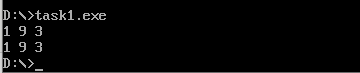
Give the program task1.asm source code, and run a screenshot
 1 assume cs:code, ds:data
 2
 3 data segment
 4     x db 1, 9, 3
 5     len1 equ $ - x
 6
 7     y dw 1, 9, 3
 8     len2 equ $ - y
 9 data ends
10
11 code segment
12 start:
13     mov ax, data
14     mov ds, ax
15
16     mov si, offset x
17     mov cx, len1
18     mov ah, 2
19  s1:mov dl, [si]
20     or dl, 30h
21     int 21h
22
23     mov dl, ' '
24     int 21h
25
26     inc si
27     loop s1
28
29     mov ah, 2
30     mov dl, 0ah
31     int 21h
32
33     mov si, offset y
34     mov cx, len2/2
35     mov ah, 2
36  s2:mov dx, [si]
37     or dl, 30h
38     int 21h
39
40     mov dl, ' '
41     int 21h
42
43     add si, 2
44     loop s2
45
46     mov ah, 4ch
47     int 21h
48 code ends
49 end start
Answer Questions 1
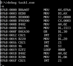
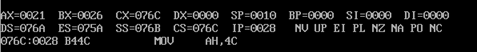
(1) line27, the assembly instruction loop s1 jumps according to the amount of displacement. Through debug disassembly, look at its machine code and analyze how much displacement it jumps? (Displacement values are answered in decimal numbers) From the perspective of the CPU, how to calculate the offset address of the instruction following the jump label s1.
Displacement: -14
F2 is converted to 10-14 by subtracting the offset address 001B of loop s1 from the offset address 000D of mov dl [si]
Answer Questions 2
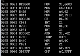
(2) line44, the assembly instruction loop s2 jumps according to the amount of displacement. Through debug disassembly, look at its machine code and analyze how much displacement it jumps? (Displacement values are answered in decimal numbers) From the perspective of the CPU, how to calculate the offset address of the instruction following the jump label s2.
Displacement: -14
F2 is converted to 10-14 using offset address 0029 of mov dl [si] minus offset address 0037 of loop s2
Question 3
(3) Disassembly screenshots of debugging observations in debug when the above analysis is attached
2. Experimental Task 2
Write this section:
Give program task2.asm source code
 1 assume cs:code, ds:data
 2
 3 data segment
 4     dw 200h, 0h, 230h, 0h
 5 data ends
 6
 7 stack segment
 8     db 16 dup(0)
 9 stack ends
10
11 code segment
12 start:
13     mov ax, data
14     mov ds, ax
15
16     mov word ptr ds:[0], offset s1
17     mov word ptr ds:[2], offset s2
18     mov ds:[4], cs
19
20     mov ax, stack
21     mov ss, ax
22     mov sp, 16
23
24     call word ptr ds:[0]
25 s1: pop ax
26
27     call dword ptr ds:[2]
28 s2: pop bx
29     pop cx
30
31     mov ah, 4ch
32     int 21h
33 code ends
34 end start
Given analysis, debugging, validation, register (ax) =? (bx) =? (cx) =? Attach a screenshot of the debug results interface.
(1) According to the jump principle of call instruction, theoretical analysis is made first. Register (ax) =? Register (bx) =? Register (cx) = before program execution (line31)?
Theoretical analysis: ax should be the offset address for the s1 tag, bx should be the offset address for the s2 tag, and cx should be the segment address
(2) Assemble and link the source program to get the executable task2.exe. Debug with debug to observe and verify whether the results of debugging are consistent with the results of theoretical analysis.
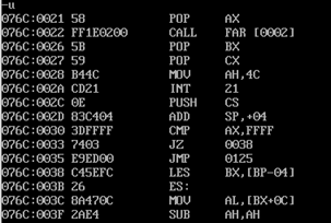
Consistent with analysis results
3. Experimental Task 3
Write this section:
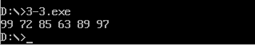
Gives a screenshot of the program source task3.asm run test
 1 assume cs:code,ds:data
 2
 3 data segment
 4 x db 99, 72, 85, 63, 89, 97, 55
 5 len equ $- x
 6 data ends
 7
 8 code segment
 9 start:
10 mov ax,data
11 mov ds,ax
12 mov si,0
13 mov cx,6
14 s:
15 mov ax,offset printNumber
16 call ax
17 mov ax,offset printSpace
18 call ax
19 loop s
20 mov ah,4ch
21 int 21h
22
23 printNumber:
24 mov ah,0
25 mov al,[si]
26 inc si
27 mov bl,10
28 div bl
29 or al,30h
30 mov bl,al
31 or ah,30h
32 mov bh,ah
33 mov ah,2
34 mov dl,bl
35 int 21h
36 mov ah,2
37 mov dl,bh
38 int 21h
39 ret
40
41
42 printSpace:
43 mov bl,' '
44 mov ah,2
45 mov dl,bl
46 int 21h
47 ret
48
49
50 code ends
51 end start
4. Experimental Task 4
Write this section:
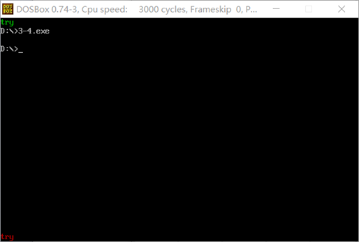
Gives a screenshot of the program source task4.asm run test
 1 assume cs:code,ds:data
 2
 3 data segment
 4 str db 'try'
 5 len equ $ - str
 6 data ends
 7
 8 code segment
 9 start:
10 mov ax,data
11 mov ds,ax
12 mov ax,0b800h
13 mov es,ax
14 mov si,0
15 mov di,0
16 mov bl,2
17 mov ax,offset printStr
18 call ax
19
20 mov ax,0b8f0h
21 mov es,ax
22 mov si,0
23 mov di,0
24 mov bl,4
25 mov ax,offset printStr
26 call ax
27
28
29 mov ah, 4ch
30 int 21h
31
32 printStr:
33 mov cx,3
34 s:
35 mov bh,[si]
36 mov  es:[di],bh
37 inc di
38 mov  es:[di],bl
39 inc si
40 inc di
41 loop s
42 ret
43
44 code ends
45 end start
5. Experimental Task 5
Write this section:
Gives a screenshot of the program source task5.asm run test
 1 assume cs:code,ds:data
 2
 3 data segment
 4 stu_no db '20192308063'
 5 len = $ - stu_no
 6 data ends
 7
 8 code segment
 9 start:
10 mov ax,data
11 mov ds,ax
12 mov ax,0b8f0h
13 mov es,ax
14 mov si,0
15 mov di,0
16 mov cx,35
17 s:
18 mov byte ptr es:[di],'-'
19 inc di
20 mov byte ptr es:[di],00010111b
21 inc di
22 loop s
23
24 mov cx,11
25 s1:
26 mov bh,[si]
27 inc si
28 mov es:[di],bh
29 inc di
30 mov byte ptr es:[di],00010111b
31 inc di
32 loop s1
33
34 mov cx,34
35 s2:
36 mov byte ptr es:[di],'-'
37 inc di
38 mov byte ptr es:[di],00010111b
39 inc di
40 loop s2
41
42 mov ah, 4ch
43 int 21h
44
45
46 code ends
47 end start

Experimental summary
In this experiment, I further understand the principle of transfer instructions by using them. Another benefit of this experiment is that you have a better understanding of the screen output of 8086 cpu. Beginning in memory space b8000 is the control screen output. Each word represents a character on the screen. The first byte represents the character assic code value, and the last byte controls the foreground, background, highlight, and flicker information of the character.