Explanation of common sensors IV - water sensor
Specific explanation
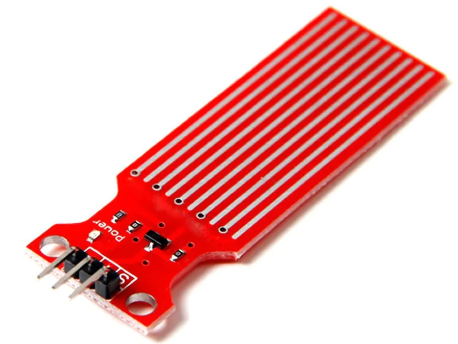
The sensor operates by using a series of five bare wires connected to system ground. Insert one sensing trace, five grounding traces and a total of five sensing traces alternately between each two grounding traces. The sense cable is connected to a 1 megohm pull-up resistor. The sensing trace is pulled up until a drop of water or a horizontal plane grounds the sensing trace. Theoretically, this sensor will output analog signals between 0-1024, but with the increase of the routing length on the PCB, I find that the available range is between 480 and 710. The sensor is not designed to be completely immersed in water, please install it carefully so that only the exposed wiring on the PCB will come into contact with water. The output voltage of the sensor is 0-4.2 V, so it can be used as a digital input if only low / high indication is required.
The analog output value corresponds to the following distance from the bottom of the sensor (approximate value):
480 = 0 mm
530 = 5mm
615 = 10 mm
660 = 15 mm
680 = 20 mm
690 = 25mm
700 = 30 mm
705 = 35 mm
Mm = 710
The sensor resolution decreases with the increase of water level.
==Installation
1. Upload the sketch to your Arduino.
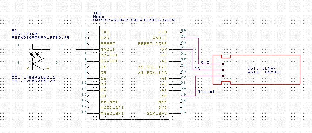
2. Assemble the circuit using the schematic diagram attached to the project.
**Led: the LED resistor must be installed between the circuit ground and the LED. If one branch of your LED is longer than the other, you need to connect the longer branch to the power supply voltage (D2 of Arduino).
*Note: the sensor wire I use is about 2.5 feet long and the LED wire is 2 feet long. This allows me to place the Arduino away from the water and wire the led to the end of the branch to improve visibility.
3. Follow the following calibration instructions (also included in the sketch):
*********Calibration / setup*********
a) Connect Arduino to the IDE and turn on the serial monitor.
b) Insert the depth sensor into the water until you think it is the minimum depth required to trigger the full indicator. Note the value indicated in the serial monitor to use as the full level.
*Any value greater than or equal to = triggers the corresponding full flashing code.
c) Repeat step 2 to determine the value you will assign to the LOW value.
*Any value higher than this value but lower than the FULL value will trigger the corresponding INTERMEDIATE flashing code.
*Any value below this value will trigger the corresponding LOW flashing code.
d) Insert the values determined in steps 2 and 3 into the const int FULL and LOW values in the sketch.
e) Upload the sketch using the updated values and the sensor is now calibrated.
4. Place Arduino on some type of enclosure to prevent water stop, moving parts or short circuit damage.
5. Install the system into your application.
Number part name part number quantity
R1 1k 1/4 W resistance TE Con polarity cfr16j1k0 (or similar) 1
L1 LED CREE C503B-RAN-CZ0C0AA2 (or similar) 1
Sol06S1 sensor
IC1 Arduino nano A000005 1
PS power supply you can select 5 Vdc (> = 300mA) 1
Circuit connection
Implementation code
const int full = 575;
const int low = 490;
int depthSensor = 0; //Set depthSensor input pin to Analog 0.
int lastValue = 0;
char printBuffer[128];

/* The following line sets the LED pin to the corresponding digital pin of the
Arduino.  You can set these to any digital pin as needed
*/

const int whiteLED = 2;

void setup()
{
Serial.begin(9600); // Begin serial communication to obtain sensor values during calibration.
pinMode(whiteLED, OUTPUT); // Set LED pin to OUTPUT mode.
}

void loop()
{
int value = analogRead(depthSensor); // Read the sensor values.
if(((lastValue >= value) && ((lastValue - value) > 10)) || (lastValue = 10)) /* If the delta
  between last and current value is > 10, display the current value. */
{
  // Displays depth sensor value to serial port.
  sprintf(printBuffer, "ADC%d level is %d\n", depthSensor, value);
  Serial.print(printBuffer);
  Serial.println();
  //Serial.println(value);
  //Serial.println();
  // Set last value to current value for next loop.
  lastValue - value;
}
if(value >= full)
{
  // FULL
  for(int x = 0; x < 3; x++){
  digitalWrite(whiteLED, HIGH);
  delay(800);
  digitalWrite(whiteLED, LOW);
  delay(800);
  }
}
else if((value < full) && (value >= low))
{
  // INTERMEDIATE
  for(int x = 0; x < 2; x++){
  digitalWrite(whiteLED, HIGH);
  delay(1000);
  }
}
else
{
  //LOW
  for(int x = 0; x < 4; x++){
  digitalWrite(whiteLED, HIGH);
  delay(100);
  digitalWrite(whiteLED, LOW);
  delay(100);
  }
}
delay(3000);  // Read current sensor value every three seconds.
}