in winter, most of us close doors and windows and rely on HVAC equipment to maintain indoor temperature. While ensuring the room temperature, we also hope to maintain the health of the atmospheric environment in the room. In view of this, we designed a simple indoor air quality detector.
1. System overview
we rely on HVAC equipment to maintain indoor temperature, humidity and ventilation level to ensure the health and comfort of residents. Therefore, we hope to design a small, simple and low-cost indoor air quality detector to monitor the air quality in our room at any time.
generally speaking, we are concerned about the temperature, humidity, concentration of inhalable particles, concentration of volatile organic compounds, etc. of the living environment. Of course, there are other parameters such as carbon dioxide concentration, but this time we only consider temperature, humidity, inhalable particulate matter concentration and volatile organic matter concentration.
for this indoor air detector, our basic idea is to design a handheld device that can quickly form and monitor temperature, humidity, inhalable particulate matter concentration and volatile organic matter concentration. This indoor air quality detector can display the temperature and humidity, inhalable particulate matter concentration and volatile organic matter concentration in real time, and can transmit the detected data to the outside.
2. Hardware design
according to the previous description, we use a temperature and humidity sensor to monitor temperature and humidity, a laser detection sensor for inhalable particles to detect the concentration of inhalable particles, and a VOC sensor to detect the concentration of volatile organic compounds.
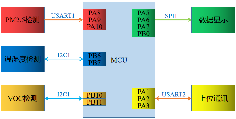
in order to quickly realize an indoor air quality detector, we use well-known sensors and other corresponding equipment. We use SHT20 to detect temperature and humidity data; Use SGP40 to detect VOC concentration; Use HLPM025K3 laser PM2 5 sensor to detect the concentration of inhalable particles; Using OLED to display data; Use serial port to realize data transmission. The processor is implemented by STM32F103C8T6.
HLPM025K3 laser PM2 5 the sensor data interface is TTL serial port, so we use USART1 port to communicate with it. The data interface of SHT20 sensor is I2C interface, and we use I2C1 to communicate with it. The data interface of SGP40 sensor is I2C interface, and we use I2C2 to communicate with it. The display adopts 0.96 inch OLED with SPI interface, so we use SPI1 port to communicate with it. Data transmission is realized by USART2 port. Therefore, we design the composition and structure diagram of indoor air quality detector as follows:
according to the above analysis and structural diagram, we can easily design the control board of indoor air quality detector.
3. Software implementation
we have described the control board and components of the indoor air quality detector. Next, we need to implement the corresponding software functions.
3.1 data acquisition
data acquisition mainly includes three aspects: first, use SHT20 to collect temperature and humidity data; Second, SGP40 is used to collect VOC concentration data; The third is to use HLPM025K3 laser PM2 5 sensor to detect inhalable particle concentration data. The collection of these data is not troublesome. In previous articles, we have briefly described the design of drivers for many of these devices. Here, we can directly use the encapsulated driver to implement it.
HLPM025K3 laser PM2 5. The sensor outputs data through serial port, including PM2 5 and PM10. We can easily obtain and parse the corresponding data by using the encapsulated driver. The specific implementation procedures are as follows:
HlpmObjectType hlpm; //Declaration object

/*PM25 Data acquisition and processing*/
void Ampm25DataProcess(void)
{
  /*Parsing PM2 5 and PM10 data*/
  ParsingPMData(&hlpm);

  aPara.phyPara.pm10Value=hlpm.pm100;
  aPara.phyPara.pm25Value=hlpm.pm25;
}

/*PM25 Data acquisition configuration*/
void Ampm25Configuration(void)
{
  /* PM25 Related GPIO initialization configuration */
  Ampm25_GPIO_Initialization();

  /* USART1 Port initialization configuration */
  USART1_Init_Configuration();

  /*Allow data transmission*/
  AMPM25_RUNNING_ENABLE();

  /*HLPM Object initialization function*/
  HlpmInitialization(&hlpm);
}
it should be noted that HLPM025K3 laser PM2 5 the sensor has a measurement control signal and must provide a high level before it can work.
similarly, we use our encapsulated driver to measure other parameters, such as using SHT20 temperature and humidity sensor to obtain temperature and humidity data.
/* Temperature and humidity data processing */
void AmShtDataProcess(void)
{
  aPara.phyPara.temperature=GetSHT2xTemperatureValue(&sht,MEASURE_T_COMMAND_NOHOST);
  aPara.phyPara.humidity=GetSHT2xHumidityValue(&sht,MEASURE_RH_COMMAND_NOHOST);
}

/* Temperature and humidity configuration */
void AmShtConfiguration(void)
{
  /* I2C1 Port initialization */
  I2C1_Init_Configuration();

  /* Initialize configuration SHT2x */
  SHT2xInitialization(&sht,        //SHT2X object variable
             SHT2x_DPI_RH8_T12, //Measurement resolution configuration
             SHT2x_End_High,   //Battery end state configuration
             SHT2xHEATERDISABLE, //Is the heater configuration enabled
             SHT2xOTPDISABLE,  //Load OTP configuration
             WriteToSHT2x,    //Write operation pointer
             ReadFromSHT2x,   //Read operation pointer
             HAL_Delay);     //Millisecond delay pointer
}
3.2 data display
as mentioned above, we have mentioned the use of 0.96 inch OLED to display corresponding data. We choose the OLED display with SPI interface. In fact, we have encapsulated the 0.96-inch OLED driver. Just use it directly. The specific implementation code is as follows:
OledObjectType oled;  //Declare OLED objects

/*OLED Display processing*/
void AmoledDisplayProcess(void)
{
  char temp[]="temp=%.2f";
  char humi[]="humi=%.2f";
  char pm25[]="PM2.5=%.2f";
  char pm10[]="PM10=%.2f";

  OledShowString(&oled,OLED_FONT_8x16,0,0,temp,aPara.phyPara.temperature);
  OledShowString(&oled,OLED_FONT_8x16,2,0,humi,aPara.phyPara.humidity);
  OledShowString(&oled,OLED_FONT_8x16,4,0,pm25,aPara.phyPara.pm25Value);
  OledShowString(&oled,OLED_FONT_8x16,6,0,pm10,aPara.phyPara.pm10Value);

}

/*OLED Initialize configuration*/
void AmoledConfiguration(void)
{
  /* OLED Display control related GPIO initialization configuration */
  Amoled_GPIO_Initialization();

  /* SPI1 Port initialization */
  SPI1_Init_Configuration();

  /*OLED Display object initialization*/
  OledInitialization(&oled,      //OLED object
             OLED_SPI,       //Communication port
             0xFF,        //I2C device address
             AmOledWrite,        //Write data function
             AmOledChipReset,       //Reset signal operation function pointer
             AmOledDCSelcet,        //DC signal control function pointer
             NULL,       //SPI chip selection signal function pointer
             HAL_Delay       //Millisecond delay function pointer
               );
}
3.3 * *. Data transmission**
for data transmission, we use RS485 interface mode, and the application layer protocol adopts Modbus RTU protocol. Because we have encapsulated the Modbus protocol stack and open source to GitHub, we directly use the Modbus protocol stack to realize our data transmission.
/* Upper communication processing function */
void AmUpperCommunication(void)
{
  uint16_t respondLength=0;
  if(amupcRxLength>=8)
  {
     uint8_t respondBytes[AMUPCRECEIVELENGTH];

      respondLength=ParsingMasterAccessCommand(amupcRxBuffer,respondBytes,amupcRxLength,aPara.phyPara.activeAddress);
     if(respondLength!=65535)
     {
       if(respondLength > 0)
       {
          AmupcSendByte(respondBytes,respondLength);
       }

       amupcRxLength=0;
     }
  }
}
for data transmission, we use serial port receiving interrupt to receive data requests. Of course, you can also directly use the method of regular upload to send data, which can be modified according to the actual needs.
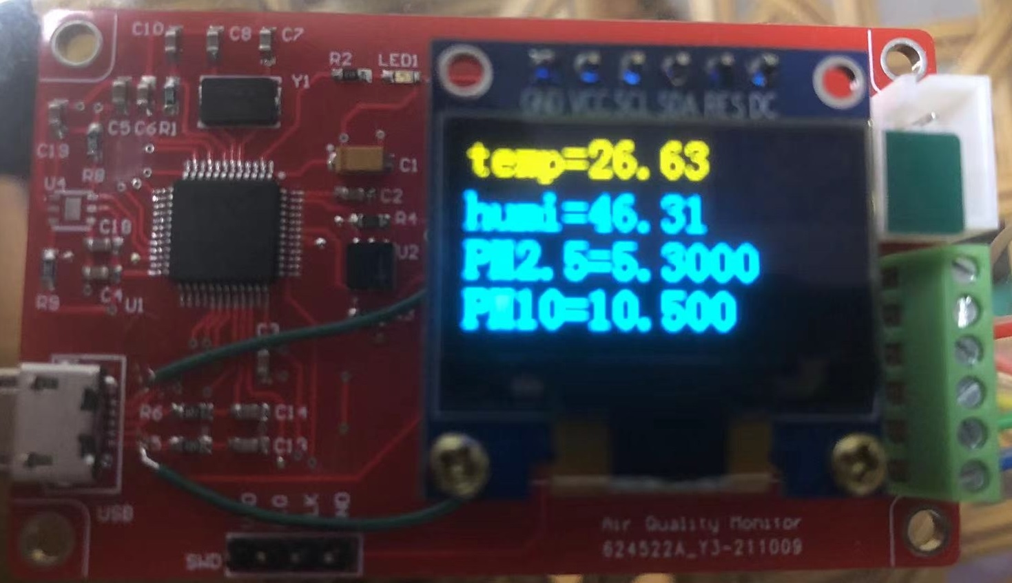
4. Verification test
we have designed the software and hardware of the indoor air quality detector. Next, let's run it to see how the results are. We run it and set it in our OLED software to display 4 rows of data at a time. The specific results are as follows:
this is just a small production, which realizes some simple functions. In the future, we can actually expand its functions more. For example, upload the data to the network to view the atmospheric environment in the room in real time; According to PM2 5. Control the operation of air purifier, etc.
Welcome to: