Combinational logic: basic logic gate
Wire
The basic description of wire linetype has been given in note arrangement (1).
Title: realize the connection between input and output.
answer:
module top_module (
    input in,
    output out);
    assign out = in;

endmodule
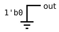
GND (ground)
Title: realize grounding the output.
answer:
module top_module (
    input in,
    output out);
    assign out = in;

endmodule
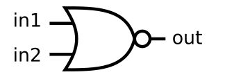
NOR (or non)
Title: implement logic or not gate.
answer:
module top_module (
    input in1,
    input in2,
    output out);
    assign out = ~(in1|in2);

endmodule
Another gate
Title: realize the following logical operation.
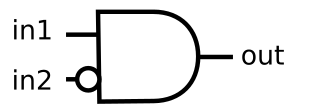
Answer: according to the given logic diagram, the two inputs are and operated, and then in2 takes the inverse input.
module top_module (
    input in1,
    input in2,
    output out);
    assign out = in1 & (~in2);

endmodule
Two gates
Title: realize the following logical operation.
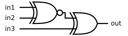
Answer: in1, in2 and in3 are three inputs, out one output and two XOR gates. An intermediate linetype needs to be added.
module top_module (
    input in1,
    input in2,
    input in3,
    output out);
    wire out1;
    assign out1 = ~ (in1^in2);
    assign out = out1^in3;

endmodule
More logic gates
Title: let's try to build several logic gates at the same time. Build a combinational circuit with two inputs a and b.
There are 7 outputs in total, and each output has a logic gate drive:
out_and: a and b
out_or: a or b
out_xor: a xor b
out_nand: a nand b
out_nor: a nor b
out_xnor: a xnor b
out_anotb: a and-not b
Answer: perform corresponding logic gate operation on each output
Insert the code slice here
module top_module(
    input a, b,
    output out_and,
    output out_or,
    output out_xor,
    output out_nand,
    output out_nor,
    output out_xnor,
    output out_anotb
);
    assign out_and = a & b;
    assign out_or = a | b;
    assign out_xor = a ^ b;
    assign out_nand = ~(a & b);
    assign out_nor = ~(a | b);
    assign out_xnor = ~(a ^ b);
    assign out_anotb = a & (~b);

endmodule
7420 chip
Title: 7400 series integrated circuit is a series of digital chips, each composed of several basic logic gates. The 7420 is a chip with two 4-input NAND gates.
Create a module with the same function as the 7420 chip. It has 8 inputs and 2 outputs.

Answer: the 7420 chip is the implementation of two NAND gates
module top_module (
    input p1a, p1b, p1c, p1d,
    output p1y,
    input p2a, p2b, p2c, p2d,
    output p2y);
    assign p1y = ~(p1a & p1b & p1c & p1d);
    assign p2y = ~(p2a & p2b & p2c & p2d);

endmodule
Truth tables
In the previous exercise, we used a simple logic gate and a combination of several logic gates. These circuits are examples of combinational circuits. Combination means that the output of a circuit is only a function of its input (in a mathematical sense). This means that for any given input value, there is only one possible output value. Therefore, one way to describe the behavior of a composite function is to explicitly list the output of each possible value of the input. This is a truth table.
For a Boolean function with N inputs, there are two possible input combinations to the nth power of 2. Each row of the truth table lists an input combination, so there are always rows to the nth power of 2. The output column shows the output corresponding to each input value.

Suppose we want to build the above circuit, but we are limited to using a set of standard logic gates. How to construct an arbitrary logic function (expressed as a truth table)?
A simple way to create a circuit that implements a truth table function is to represent the function in the form of product sum. Summation is the or operation, and product is the and operation. First, an N-input and gate is used to determine whether the input vector matches the truth table, and then an OR gate is used to select the results that meet the matching conditions for output.
Title: create a combinational circuit to realize the above truth table.
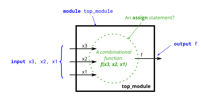
answer:
module top_module(
    input x3,
    input x2,
    input x1,  // three inputs
    output f   // one output
);
    assign f = ((~x3)&x2&(~x1))|((~x3)&x2&x1)|(x3&(~x2)&x1)|(x3&x2&x1);

endmodule
Two-bit equality
Title: create a circuit with two 2-bit inputs a[1:0] and B[1:0], and generate an output z. If A=B, the value of z should be 1, otherwise z should be 0.
Answer: equivalent to conditional judgment
module top_module ( input [1:0] A, input [1:0] B, output z );
    assign z=(A==B)?1'b1:1'b0;

endmodule
Simple circuit A
Title: module A should implement the function z = (x^y) & X.
Answer: simple assign assignment statement
module top_module (input x, input y, output z);
    assign z=(x^y)&x;
endmodule
Simple circuit B
Title: circuit B can be described by the following simulation waveform:
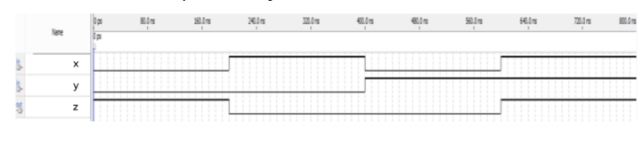
Answer: according to the waveform analysis, x and y are the same, z takes 1, and different takes 0. That is to take the inverse based on the XOR operation of x and y.
module top_module ( input x, input y, output z );
    assign z=~(x^y);

endmodule
Combine circuits A and B
Title: the top-level design consists of each instance of two sub circuits A and B, as shown below.

answer:
module top_module (input x, input y, output z);
    wire z1;
    wire z2;

    assign z1 = (x ^ y) & x;
    assign z2 = ~(x ^ y);
    assign z = (z1 | z2) ^ (z1 & z2);

endmodule
Ring or vibrate?
When designing a circuit, people often have to think about this problem "backward", starting from the output and then working in the opposite direction towards the input. This is usually the opposite of the way people think about (sequential, imperative) programming problems. In this case, people first look at the input and then decide on an operation (or output). For sequential programs, people usually think that "if (the input is * *), then (the output should be * *)". On the other hand, hardware designers usually think that "when (input is * *) (output should be * *)".
Try to use only the assign statement to see if you can convert the problem description into a collection of logical gates.
Title: design a circuit to control the ring tone and vibration motor of mobile phone. When there is an incoming call input signal (input ring), the circuit must turn on the ring (output ringer= 1) or motor (output motor= 1), but not at the same time. If the phone is in vibration mode (input vibration_mode = 1), turn on the motor. Otherwise, turn on the bell.
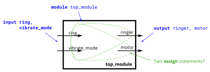
Answer: the question cannot be opened at the same time, that is, the logic and operation of the two inputs.
vibrate_ When mode = 1, turn on the corresponding motor of the mobile phone, then vibrate_ When mode = 0, the ring corresponds to ringer.
module top_module (
    input ring,
    input vibrate_mode,
    output ringer,       // Make sound
    output motor         // Vibrate
);
    assign ringer = ring & (~vibrate_mode);
    assign motor = ring & vibrate_mode;

endmodule
Thermostat
Title: heating / cooling thermostat controls heater (winter) and air conditioner (summer). Install a circuit to turn on and off the heater, air conditioner and blower fan as required.
The thermostat can be in one of two modes: heating (mode = 1) and cooling (mode = 0). In heating mode, turn on the heater when it is too cold (too cold = 1), but do not use the air conditioner. In cooling mode, turn on the air conditioner when the air conditioner is too hot (too hot = 1), but do not turn on the heater. When the heater or air conditioner is turned on, the fan is also turned on to circulate the air. In addition, even if the heater and air conditioner are off, the user can request to turn on the fan (fan on = 1).
Try to use only the assign statement to see if you can convert the problem description into a collection of logical gates.
answer:
module top_module (
    input too_cold,
    input too_hot,
    input mode,
    input fan_on,
    output heater,
    output aircon,
    output fan
);
    assign heater = mode & too_cold;
    assign aircon = (~mode) & too_hot;
    assign fan = (mode & too_cold) | ((~mode) & too_hot) | fan_on;

endmodule
3-bit population count
Title: "population counting" circuit calculates the number of "1" in the input vector. Construct an overall counting circuit for the 3-bit input vector.
Answer: the counting function will be simpler in the form of for loop traversal.
module top_module(
    input [2:0] in,
    output [1:0] out );
    integer i;
    always @(*)
    begin
        out = 2'b0;
        for(i=0;i<3;i++)
        begin
            out = out + in[i];
        end
    end

endmodule
Gatesv
Title: a four bit input vector is given in [3:0]. We want to know some relationships between each bit and its neighbors:
1)out_both: each bit of this output vector should indicate whether the corresponding input bit and the adjacent bit to its left (higher index) are "1". For example, out_both[2] should indicate whether in[2] and in[3] are both 1. Because in[3] has no neighbors on the left, the answer is obvious, so we don't need to know out_both[3].
2)out_any: each bit of this output vector should indicate whether the corresponding input bit and its adjacent bit to the right are "1". For example, out_any[2] should indicate that in[2] or in[1] is 1. Because in[0] has no neighbors on the right, the answer is obvious, so we don't need to know out_any[0].
3)out_different: each bit of this output vector should indicate whether the corresponding input bit is different from its adjacent bit to the left. For example, out_different[2] should indicate whether in[2] is different from in[3]. For this part, the vector is treated as a surround, so the neighbor to the left of in[3] is in [0].
Answer: the three outputs obtained from the topic analysis are used for and, or and XOR operations respectively.
module top_module(
    input [3:0] in,
    output [2:0] out_both,
    output [3:1] out_any,
    output [3:0] out_different);
    integer i;
    always @(*)
    begin
        for(i=0;i<3;i++)
        begin
            out_both[i] = in[i] & in[i+1];
            out_any[i+1] = in[i+1] | in[i];
            out_different[i] = in[i] ^ in[i+1];
        end
        out_different[3] = in[0] ^ in[3];//Traverse the missing and need to fill it up
    end

endmodule
Even longer vectors
Title: same as the previous one. Only the input vector has changed from 4 bits to 100 bits.
Answer: the same idea for solving problems
module top_module(
    input [99:0] in,
    output [98:0] out_both,
    output [99:1] out_any,
    output [99:0] out_different);
	integer i;
    always @(*)
    begin
        for(i=0;i<99;i++)
        begin
            out_both[i] = in[i] & in[i+1];
            out_any[i+1] = in[i+1] | in[i];
            out_different[i] = in[i] ^ in[i+1];
        end
        out_different[99] = in[0] ^ in[99];
    end

endmodule
The above is the circuits basic gates section of HDLBits Verilog language question brushing website, and the subsequent sections will continue to be updated. Summarize some basic knowledge points. Please correct any mistakes. For learning reference only, thank you!!!