GPIO of TM4C123G MCU
1. Output: Light up LED

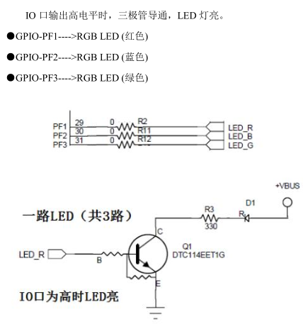
Schematic diagram
IO port output high level light LED, next we learn how to control the high and low level of IO port.
- Method 1:
SysCtlPeripheralEnable(SYSCTL_PERIPH_GPIOF);			//Port F peripheral enablement
GPIOPinTypeGPIOOutput(GPIO_PORTF_BASE, GPIO_PIN_1);		//PF1 is set to output
GPIOPinWrite(GPIO_PORTF_BASE, GPIO_PIN_1, GPIO_PIN_1);	//PF1 Output High Level
The corresponding PF1 is low:
GPIO PinWrite (GPIO_PORTF_BASE, GPIO_PIN_1, 0); //PF1 Output Low Level
- Mode two:
SysCtlPeripheralEnable(SYSCTL_PERIPH_GPIOF);
GPIOPadConfigSet(GPIO_PORTF_BASE,GPIO_PIN_1,GPIO_STRENGTH_2MA,GPIO_PIN_TYPE_STD);
GPIODirModeSet(GPIO_PORTF_BASE, GPIO_PIN_1, GPIO_DIR_MODE_OUT);
GPIOPinWrite(GPIO_PORTF_BASE, GPIO_PIN_1, GPIO_PIN_1);
The two approaches are actually the same, because the GPIOPinTypeGPIOOutput function is encapsulated once again, so you can see its definition:
void
GPIOPinTypeGPIOOutput(uint32_t ui32Port, uint8_t ui8Pins)
{
    //
    // Check the arguments.
    //
    ASSERT(_GPIOBaseValid(ui32Port));

    //
    // Set the pad(s) for standard push-pull operation.
    //
    GPIOPadConfigSet(ui32Port, ui8Pins, GPIO_STRENGTH_2MA, GPIO_PIN_TYPE_STD);

    //
    // Make the pin(s) be outputs.
    //
    GPIODirModeSet(ui32Port, ui8Pins, GPIO_DIR_MODE_OUT);
}
You can see that it contains two functions, GPIOPadConfigSet and GPIODirModeSet. The detailed use of these two functions is explained in detail when learning GPIO input.
2. Input: Keyboard Detection

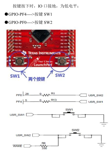
Schematic diagram
First, the IO port is initialized as input mode:
SysCtlPeripheralEnable(SYSCTL_PERIPH_GPIOF);
GPIODirModeSet(GPIO_PORTF_BASE, GPIO_PIN_4, GPIO_DIR_MODE_IN);
GPIOPadConfigSet(GPIO_PORTF_BASE,GPIO_PIN_4,GPIO_STRENGTH_2MA, GPIO_PIN_TYPE_STD_WPU);
Here are two functions of GPIODirModeSet and GPIOPadConfigSet
1. GPIODirModeSet mainly sets the direction of a port. Here we mainly look at the third parameter. There are several choices as follows:
#define GPIO_DIR_MODE_IN        0x00000000  // Pin is a GPIO input
#define GPIO_DIR_MODE_OUT       0x00000001  // Pin is a GPIO output
#define GPIO_DIR_MODE_HW        0x00000002  // Pin is a peripheral function
You can see the meaning of the name at a glance.
2. GPIOPadConfigSet Sets IO Port
Look at the choice of the third parameter:
#define GPIO_STRENGTH_2MA       0x00000001  // 2mA drive strength
#define GPIO_STRENGTH_4MA       0x00000002  // 4mA drive strength
#define GPIO_STRENGTH_6MA       0x00000065  // 6mA drive strength
#define GPIO_STRENGTH_8MA       0x00000066  // 8mA drive strength
#define GPIO_STRENGTH_8MA_SC    0x0000006E  // 8mA drive with slew rate control
#define GPIO_STRENGTH_10MA      0x00000075  // 10mA drive strength
#define GPIO_STRENGTH_12MA      0x00000077  // 12mA drive strength
Setting current intensity
Look at the choice of the fourth parameter:
#define GPIO_PIN_TYPE_STD       0x00000008  // Push-pull
#define GPIO_PIN_TYPE_STD_WPU   0x0000000A  // Push-pull with weak pull-up
#define GPIO_PIN_TYPE_STD_WPD   0x0000000C  // Push-pull with weak pull-down
#define GPIO_PIN_TYPE_OD        0x00000009  // Open-drain
#define GPIO_PIN_TYPE_ANALOG    0x00000000  // Analog comparator
#define GPIO_PIN_TYPE_WAKE_HIGH 0x00000208  // Hibernate wake, high
#define GPIO_PIN_TYPE_WAKE_LOW  0x00000108  // Hibernate wake, low
That is, set push-pull, pull-down, which is generally used as output (GPIO_PIN_TYPE_STD), pull-up (GPIO_PIN_TYPE_STD_WPU) or drop-down (GPIO_PIN_TYPE_STD_WPD) as input.
After initializing the IO port as input mode, the level state of the IO port can be read.
GPIOPinRead(GPIO_PORTF_BASE, GPIO_PIN_4)
The return value of this function, taking PF4 as an example, when PF4 is 8 bits lower than the return value at high level: 00010000, that is 16. When the PF4 bit low level returns to 0.
Sample code
Function: Press the button to turn on the light and turn off the light.
#include <stdint.h>
#include <stdbool.h>
#include "inc/hw_gpio.h"
#include "driverlib/gpio.h"
#include "driverlib/pin_map.h"
#include "inc/hw_memmap.h"
#include "driverlib/sysctl.h"

int main()
{
    SysCtlPeripheralEnable(SYSCTL_PERIPH_GPIOF);
    //Set PF4 as pull-up input mode
    GPIODirModeSet(GPIO_PORTF_BASE, GPIO_PIN_4, GPIO_DIR_MODE_IN);
    GPIOPadConfigSet(GPIO_PORTF_BASE, GPIO_PIN_4, GPIO_STRENGTH_2MA, GPIO_PIN_TYPE_STD_WPU);

    //Set PF1 as output mode
    GPIOPinTypeGPIOOutput(GPIO_PORTF_BASE, GPIO_PIN_1);
    GPIOPinWrite(GPIO_PORTF_BASE, GPIO_PIN_1, 0);

    //Keyboard detection
    while(1)
    {
        //Not pressed for high level
        if(GPIO_PIN_4 == GPIOPinRead(GPIO_PORTF_BASE, GPIO_PIN_4))
            GPIOPinWrite(GPIO_PORTF_BASE, GPIO_PIN_1, 0);
        //Be pressed
        else
            GPIOPinWrite(GPIO_PORTF_BASE, GPIO_PIN_1, GPIO_PIN_1);
    }
}