
Experimental introduction
"Electronic compass", as a very common function, is almost equipped with smart phones on the market by default. In life, it can help us find the right direction, assist in positioning and so on. In addition to mobile phones, electronic compass is also widely used in aviation, aerospace, robotics, navigation, vehicle autonomous navigation and other fields. In this experiment, we also implement an "electronic compass".
As can be seen from the above figure, with the rotation of the direction, the pointer and degree on the screen are also changing. The scale pointed by the pointer indicates the angle and degree of the direction indicated by the arrow. The method to achieve this effect is very simple. You only need to obtain the reading of the electronic compass sensor, and then draw the compass interface according to the reading.
Knowledge points involved
- Principle and application of QMC5883L three-axis AMR magnetic sensor
- OLED drawing
Development environment preparation
Hardware
One computer for development
HAAS EDU K1 Development board
USB2TypeC One data cable
Software
Construction of AliOS Things development environment
For the construction of development environment, please refer to @ref HaaS_EDU_K1_Quick_Start (Chapter of building development environment),Which describes in detail AliOS Things 3.3 of IDE Construction process of integrated development environment.
HaaS EDU K1 DEMO code download
HaaS EDU K1 DEMO For code download, please refer to @ref HaaS_EDU_K1_Quick_Start (Create project section),Among them,
Choose a solution: Example based on education development board
 Select development board: haaseduk1 board configure
Code compilation and burning
reference resources @ref HaaS_EDU_K1_Quick_Start (3.1 Compile engineering section),click ✅ The firmware can be compiled.
reference resources @ref HaaS_EDU_K1_Quick_Start (3.2 Burn mirror chapter),click "⚡️" The firmware can be burned.
Hardware introduction - QMC5883L
DataSheet
The quickest and most accurate way to understand an IC is to check its DataSheet. The DataSheet of this IC can be obtained at the following link.
QMC5883L-Datasheet-1.0.pdf
Hardware specifications
QMC5883L is a multi chip triaxial magnetic sensor. It is designed for high-precision applications such as compass, navigation and games in UAV, robot, mobile and personal handheld devices. QMC5883L adopts heterogeneous magnetoresistance (AMR) technology. These anisotropic sensors have the characteristics of high axial sensitivity and linear high precision. The solid-phase structure with low sensitivity to the orthogonal axis of the sensor can be used to measure the direction and size of the earth's magnetic field, and its measurement range is from milligauss to 8 Gauss. It has the advantages of low noise, high precision, low power consumption, offset elimination and temperature compensation. QMC5883L can achieve compass heading accuracy of 1 ° to 2 °. Use I2C serial bus to simplify the interface.
For more detailed hardware specifications, please refer to 2.1 Product Specifications of DataSheet
Sensing principle
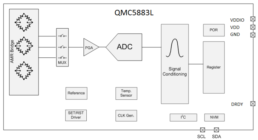
Through this internal schematic diagram, we can clearly see that there are three groups of two orthogonal MAGNETORESISTANCES in QMC5883L. The resistance value of this special resistance will change with the applied magnetic field. Therefore, using the analog-to-digital converter to read this change, we can obtain the change information of the device in the magnetic field and judge the direction of the device.
weather phenomenon
- AMR Bridge: triaxial out of phase magnetoresistive sensor. Its structure is a resistance bridge, and its resistance will change with the applied magnetic field. The three sensors are orthogonal to each other, so that the magnetic field intensity in three directions can be obtained.
- MUX: multiplex channel. Select the corresponding channel through the switch to collect the sensor data of the channel.
- PGA: programmable sensor signal gain amplifier.
- Signal Conditioning: digital module for magnetic field signal correction and compensation.
- ADC: analog-to-digital converter, which is used to convert the analog signal obtained at the sensor side into digital signal.
- NVM: nonvolatile memory for correction.
- SET/RST Driver: used to initialize the internal drive of magnetic sensor.
- Reference: voltage / current reference for internal offset.
- Temperature Sensor: a Temperature Sensor used for internal accuracy / offset. It can also be used to measure temperature and output.
Driving mode
communication interface
According to the DataSheet, the communication mode adopted by QMC5883L is I2C. Default 7bit device address: 0x0D (DataSheet P10 5.4)
In AliOS Things 3.3, VFS is used for I2C operation. The developer only needs to open the corresponding device. The developer only needs to care about the I2C device number linked to, the device address of the slave device and the I2C rate supported by the slave device. After knowing the slave device address, the read-write address can also be calculated. AliOS Things will automatically process these calculations. Therefore:
Write address of I2C device = I2C device address < < 1 = 0x0D < < 1 = 0x1a
Read address of I2C device = (I2C device address < < 1) + 1 = 0x1b
This is also consistent with the conclusion given in Datasheet P14 I2C R / W operation.
If we need to initialize the I2C interface for QMC5883L, the corresponding code is:
int32_t ret = sensor_i2c_open(QMC5883L_I2C_PORT, QMC5883L_ADDR, I2C_BUS_BIT_RATES_100K, 0);
if (ret) {
    LOGE("SENSOR", "sensor i2c open failed, ret:%d\n", ret);
    return;
}
Register address
Generally, devices using I2C communication complete the reading and configuration of devices by reading and writing registers. Therefore, it is very important to understand the distribution of registers. Consult DataSheet(from DataSheet P16 9.1 Register Map) to get:
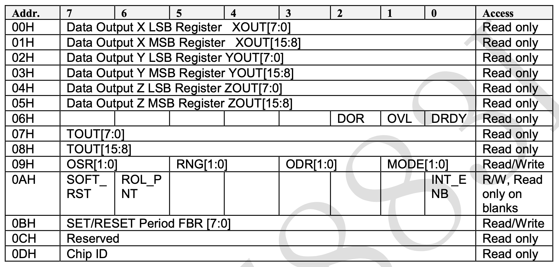
Among them, according to different Access attributes, we are divided into read-only registers and read-write registers to analyze some important registers in the driving process.
Read only register (output register)
Read only registers are generally used to read the status and sampling data of the device.
Table 14. Output Data Register
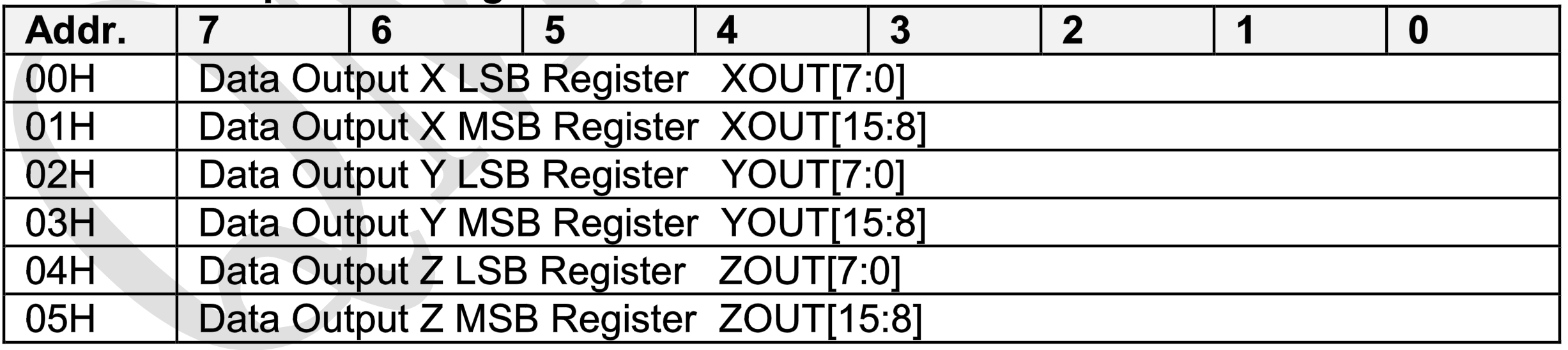
- Data Output X Y Z LSB&MSB 00H-05H
For the sampling data of three axes, the output data of each axis is 16bit, which is stored in two 8bit registers respectively.
Read / write register (configuration register)
Read write registers are generally used to configure devices. For QMC5883L, its initialization only needs to care about this register 09H.
Table 18. Control Register 1
- OSR
Over Sample Ratio register. Used to control the bandwidth of the internal digital filter. Larger OSR values result in smaller filter bandwidth, less in band noise and higher power consumption. A good balance between noise and power can be achieved by configuring this register.
- RNG
Range range selection register. The sensing range of the magnetic sensor can be configured through the register RNG. The selection of measuring range should be determined by the specific application scenario. For the environment with clear magnetism, a smaller range should be selected in the environment with weak magnetic field, such as + / - 2 gauss. The measuring range is closely related to the sensitivity of the magnetic sensor. When the number of sampling bits remains unchanged, the lowest range has the highest sensitivity, so the resolution is higher.
- ODR
Output Data Rate output data frequency register.
- MODE
Mode control register. Used to configure whether the device turns on continuous measurement mode. In the x-output mode, only 6 consecutive measurement registers need to be refreshed, and the data can be read continuously from the x-output mode.
Drive implementation
After completing the initialization of I2C, we can initialize QMC5883L. In AliOS Things 3.3, we have partially abstracted the device, which can be configured during initialization.
// solutions/eduk1_demo/drivers/sensor/drv_mag_honeywell_qmc5883l.c
// solutions/eduk1_demo/drivers/sensor/drv_mag_honeywell_qmc5883l.h

static void _qmc5883l_init() {
    /* This assumes the wire library has been initialized. */
    addr = QMC5883L_ADDR;
    oversampling = QMC5883L_CONFIG_OS512;		// 512 times oversampling
    range = QMC5883L_CONFIG_8GAUSS;				// 8 Gauss range
    rate = QMC5883L_CONFIG_200HZ;				// 200Hz data output frequency
    mode = QMC5883L_CONFIG_CONT;				// Continuous sampling mode on
    qmc5883l_reset();
}
After the configuration is completed, the driver will write data to the corresponding register.
// solutions/eduk1_demo/drivers/sensor/drv_mag_honeywell_qmc5883l.c
// solutions/eduk1_demo/drivers/sensor/drv_mag_honeywell_qmc5883l.h

# define QMC5883L_CONFIG2 0x09
# define QMC5883L_CONFIG2 0x0a

static qmc5883l_write_register(uint8_t addr, uint8_t reg, uint8_t data)
{
    uint8_t write_buffer[2] = {reg, data};
    qmc5883l_i2c_master_send(write_buffer, 2, 1000);
}

static void qmc5883l_reconfig()
{
    qmc5883l_write_register(addr, QMC5883L_CONFIG, oversampling|range|rate|mode);	// Write configuration data to 0x09 configuration register
    qmc5883l_write_register(addr, QMC5883L_CONFIG2, 0x1);    						// Soft restart
}
Similarly, if you need to read the register, you need to write the target read address to the device first, and then read the device data.
// solutions/eduk1_demo/drivers/sensor/drv_mag_honeywell_qmc5883l.c
// solutions/eduk1_demo/drivers/sensor/drv_mag_honeywell_qmc5883l.h
uint8_t qmc5883l_read_len(uint8_t addr, uint8_t reg, uint8_t *buf, uint8_t len)
{
qmc5883l_i2c_master_send(®, 1, 1000);
aos_msleep(20);
qmc5883l_i2c_master_recv(buf, len, 1000);
return 1;
}
int qmc5883l_readRaw(int16_t *x, int16_t *y, int16_t *z)
{
uint8_t data[6];
uint32_t timeout = 10000;
while(!qmc5883l_ready() && (timeout--));
if(!qmc5883l_read_len(addr, QMC5883L_X_LSB, data, 6)) return 0;
*x = data[0] | (data[1]<<8);
*y = data[2] | (data[3]<<8);
*z = data[4] | (data[5]<<8);
printf("get org data [%d,%d,%d]\n", x, y, z);
return 1;
}
At this point, the sampling data can be read out from QMC5883L. Because the electronic compass only needs the direction information of the plane, it only needs to be used
atan2(x_fit, y_fit) * 180.0 / M_PI;
// atan2(x, y) returns the arctangent of y/x in radians
You can get the current pointing information.
However, the angle obtained from the original data will be very inaccurate. Therefore, we need to calibrate the data next.
Data calibration
Raw data sampling
Through the int qmc5883l implemented in the previous article_ Readraw (int16_t * x, int16_t * y, int16_t * z) function, we can sample the device in all directions. Because we are mainly concerned about the data of X and Y axes, we need to traverse all directions of the device on the horizontal plane and read the data. The data is printed on the serial port through printf("get org data [%d,%d,%d]\n", x, y, z).
The specific method is to slowly rotate HaaS EDK on the horizontal plane to cover at least one complete circle, and ensure that there is no magnetic interference around during this process (such as any object containing magnetism).
The collected data are as follows:
org_list = [
    [-1438,-1690,-2665],
	[-1438,-1690,-2665],
	[-1446,-1660,-2667],
	[-1418,-1642,-2702],
    ...
]
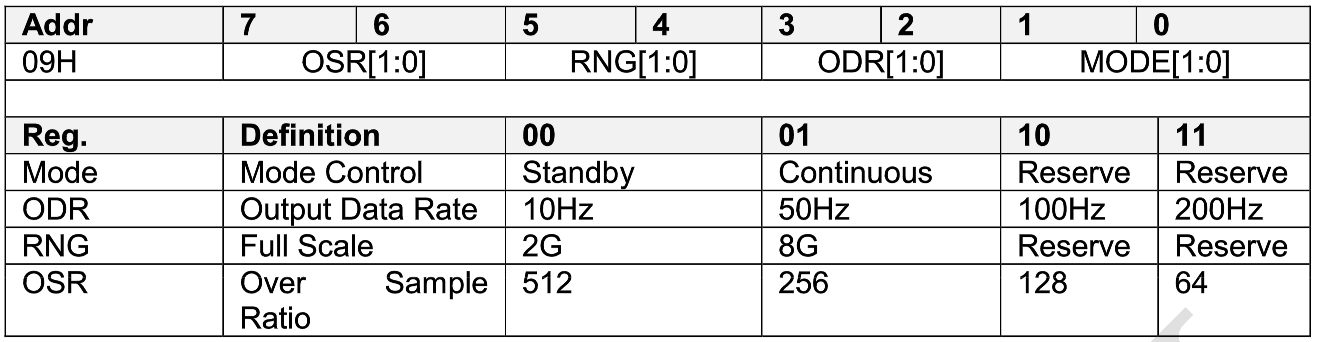
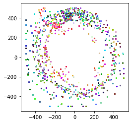
We use matploatlib to visualize this data as a scatter diagram. The X and Y axes of the scatter diagram represent the X and Y axis data read from QMC5883L respectively. The color of the points marks the sequence of sampling points from front to back from dark to light.
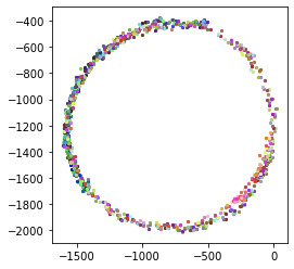
It can be observed that with our rotation, the scattered points form a relatively complete circle, indicating that the sensitivity of the two magnetic sensors of X and Y axes to the change of magnetic field is roughly the same, that is, the resistance change caused by the change of equal magnetic flux is similar, so it can show a relatively standard circle. If the sensitivity of the two sensors is quite different, the situation in the figure on the right will appear. The response of the x-axis is more sensitive, and the interval measured on the x-axis is larger and the x-axis is longer, which is similar to an ellipse.
Since we use atan2 method to map the X-Y axis data to the polar coordinate system, if we want to get accurate mapping, we need to ensure that the center of the circle is in (0, 0) position. However, it can be seen from these two figures that the center of the circle deviates from (0, 0). Therefore, we first need to find the coordinates of the center of the circle (the center of the ball for the triaxial).
For some devices, the sensitivity of different axes may be inconsistent. We can reduce the three axes to the same scale through the following formula. Where, x_min,x_max represents the data boundary, x_offset represents the corrected data center.
\dfrac{x-x_{offset}}{x_{\max}-x_{\min }}=\dfrac{y-y_{offset}}{y_{\max}-y_{\min }}=\dfrac{z-z_{offset}}{z_{\max}-z_{\min }}
 x_max = y_max = z_max = INT16_MIN;
 x_min = y_min = z_min = INT16_MAX;

int qmc5883l_readHeading()
{
    int16_t x_org, y_org, z_org;		// raw data
    float x_offset, y_offset, z_offset;	// Spherical center coordinate offset
    float x_fit, y_fit, z_fit;			// Correction data

    if (!qmc5883l_readRaw(&x_org, &y_org, &z_org))
        return 0;

    // The data boundary is updated every time the data is read
    x_min = x_org < x_min ? x_org : x_min;
    x_max = x_org > x_max ? x_org : x_max;
    y_min = y_org < y_min ? y_org : y_min;
    y_max = y_org > y_max ? y_org : y_max;
    z_min = z_org < z_min ? z_org : z_min;
    z_max = z_org > z_max ? z_org : z_max;

    // Exit if the amount of data is insufficient to calculate the boundary
    if (x_min == x_max || y_min == y_max || z_max == z_min)
        return 0;

    // The center offset is calculated from the boundary
    x_offset = (x_max + x_min) / 2.0;
    y_offset = (y_max + y_min) / 2.0;
    z_offset = (z_max + z_min) / 2.0;

	// Correction ratio
    x_fit = (x_org - x_offset) * 1000.0 / (x_max - x_min);
    y_fit = (y_org - y_offset) * 1000.0 / (y_max - y_min);
    z_fit = (z_org - z_offset) * 1000.0 / (z_max - z_min);

    printf("fix[%f,%f,%f],\n", x_fit, y_fit, z_fit);

    int heading = 180.0 * atan2(x_fit, y_fit) / M_PI;
    heading = (heading <= 0) ? (heading + 360) : heading;

    return heading;
}
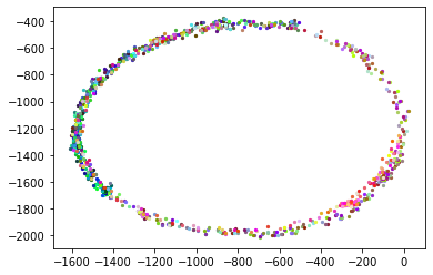
The following figure shows the data obtained after adding the correction algorithm. It can be seen that as the color becomes lighter, the amount of data increases, and the scattered points are gradually fitted to a circle with the center of the circle at (0,0).
So far, we have obtained more accurate orientation data.
Interface development
In the interface development of this experiment, the following methods are used:
while (1)
{
    heading = qmc5883l_readHeading(); // Read electronic compass data

    OLED_Clear();					// Clean up the information of the last painting
    OLED_Icon_Draw(COMPASS_CENTER_X - 27, COMPASS_CENTER_Y - 27, &icon_compass_55_55, 0);	// Used to draw the compass surface
    OLED_DrawLine_ByAngle(COMPASS_CENTER_X, COMPASS_CENTER_Y, (-heading-90), arror_len, 1);	// Pointer for drawing compass
    OLED_Show_String(96, 4, code_str, 24, 1);		// Character used to draw direction
    OLED_Show_String(78, 36, number_str, 24, 1);	// Used to plot directional readings
    OLED_Refresh_GRAM();			// Display the screen on the screen

    aos_msleep(30);
}
Developer Support
HaaS official: https://haas.iot.aliyun.com/
HaaS technology community: https://blog.csdn.net/HaaSTech
The developers' nail group and official account are shown below, and developers' staple groups have technical support students on duty every day.