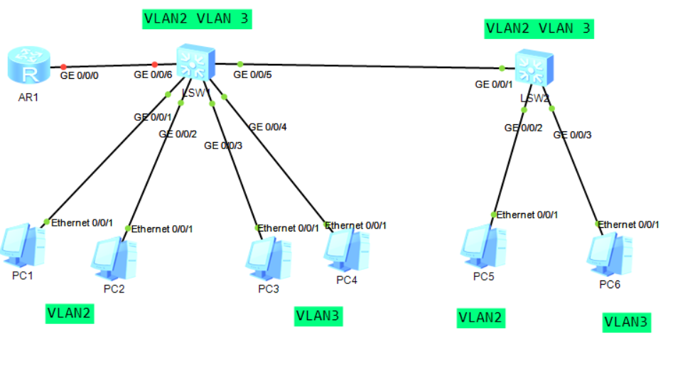
1, Topology diagram:
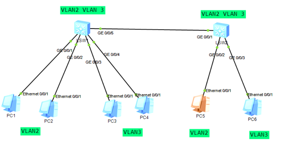
2, Basic configuration:
1: Create VLAN
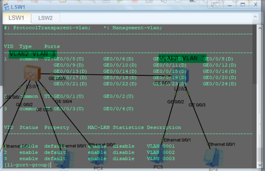
<Huawei>display vlan --- see VLAN information
[Huawei]vlan 2 --- establish VLAN
[Huawei-vlan2]q
[Huawei]undo vlan 2 --- delete VLAN
[Huawei]vlan batch 2 to 100 --- Batch creation VLAN
[Huawei]vlan batch 2 to 100 --- Batch delete VLAN
<Huawei>undo terminal monitor ---- Close error log
2: Assign the interface to the corresponding VLAN
Switch forwarding principle after adding VLAN: data enters the switch through the interface. The switch first records the mapping relationship between its source MAC and the interface, and records the VID corresponding to the interface in the MAC address table. Then look at the target MAC address. If the target MAC address is recorded in the MAC address table and its corresponding VID is the same as that of the source MAC, unicast is performed; Otherwise, conduct flooding, and the flooding range is the same interface as the VID of all interfaces corresponding to the source MAC.
The ieee-802.1q standard calls the tag that distinguishes different VLANs as tag (4 bytes, of which 12 is VID), adds the tag between the source MAC address and the TYPE field, and we call the frame that adds the tag as 802.1Q frame or tagged frame; Frames that are not tagged are called untagged frames. We call the link between the switch and the computer Access link. The Access link can only pass untagged frames, and these frames belong to the same specific VLAN. We call the link between switches as trunk link
(trunk trunk road). tagged frames can be passed in trunk road, and these frames can belong to multiple VLAN s.
3: Configure TRUNK road (SW - SW, SW - R)
[Huawei-GigabitEthernet0/0/1]port link-type access
 [Huawei-GigabitEthernet0/0/1]port default vlan 2 --- Divide the interface into VLAN
[Huawei]port-group group-member GigabitEthernet 0/0/3 to GigabitEthernet 0/0/4
[Huawei-port-group] --- Create Interface Group
[Huawei-GigabitEthernet0/0/5]port link-type trunk
[Huawei-GigabitEthernet0/0/5]port trunk allow-pass vlan 2 to 3
[Huawei-GigabitEthernet0/0/5]
[Huawei-GigabitEthernet0/0/1]port trunk allow-pass vlan all
[Huawei-GigabitEthernet0/0/1]
4: Inter VLAN Routing - single arm routing sub interface: logically divide a physical interface into multiple virtual interfaces.
Configure sub interface
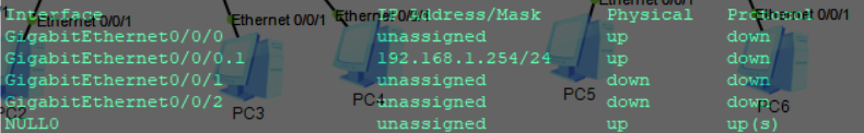
[Huawei]int g 0/0/0.1 --- Create sub interface
[Huawei-GigabitEthernet0/0/0.1]
[Huawei-GigabitEthernet0/0/0.1]ip address 192.168.1.254 24 --- Configure sub interface IP
[Huawei-GigabitEthernet0/0/0.1]dot1q(802.1Q (nickname) termination vid 2 --- Define sub interfaces
[Huawei-GigabitEthernet0/0/0.1]dot1q(802.1Q (nickname) termination vid 2 --- Define sub interfaces
 Managed VLAN
[Huawei-GigabitEthernet0/0/0.1]arp broadcast enable ---- open ARP radio broadcast
l1:
[l1]int g 0/0/1
[l1-GigabitEthernet0/0/1]port link-type access
[l1-GigabitEthernet0/0/1]port default vlan 2
[l1-GigabitEthernet0/0/2]port link-type access
[l1-GigabitEthernet0/0/2]port default vlan 2
[l1]port-group group-member  GigabitEthernet 0/0/3 to GigabitEthernet 0/0/4
[l1-GigabitEthernet0/0/4]port link-type  access
[l1-port-group]port default vlan 3
[l1-GigabitEthernet0/0/3]port default vlan 3
[l1-GigabitEthernet0/0/4]port default vlan 3
l2:
[l2-vlan3]int g 0/0/2
[l2-GigabitEthernet0/0/2]port link-type  access
[l2-GigabitEthernet0/0/2]port default vlan  2
[l2-GigabitEthernet0/0/3]port link-type access
[l2-GigabitEthernet0/0/3]port default vlan  3

Configure trunk road:
[l1-GigabitEthernet0/0/5]port link-type trunk
[l1-GigabitEthernet0/0/5]port trunk allow-pass vlan 2 to 3
[l2-GigabitEthernet0/0/1]port link-type  trunk
[l2-GigabitEthernet0/0/1]port trunk allow-pass vlan all
At this time, only the same broadcast domain can communicate; But this must have disadvantages and inappropriate.
Therefore, the improvement scheme: change 346 to 2.0 network segment
Add a router:
Enter sub interface configuration IP:
[r1]int g 0/0/0.1
[r1-GigabitEthernet0/0/0.1]ip add 192.168.1.254 24
Define VLAN s managed by sub interfaces:
[r1-GigabitEthernet0/0/0.1]dot1q termination vid 2
Turn on ARP broadcast:
[r1-GigabitEthernet0/0/0.1]arp broadcast enable
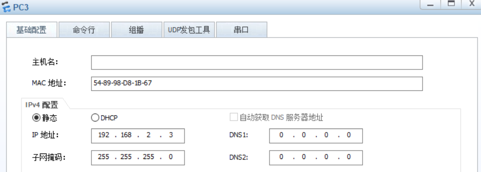
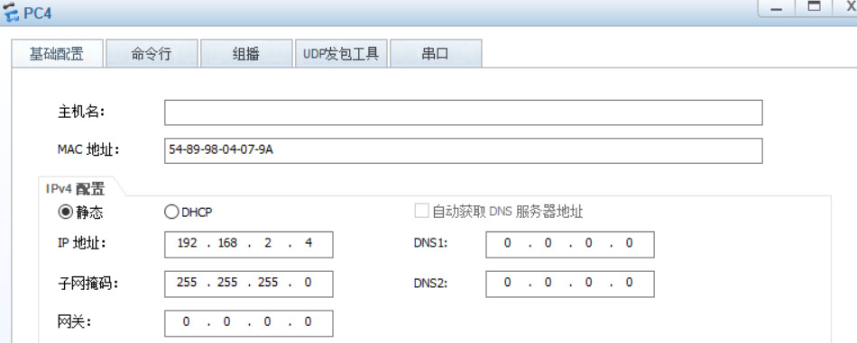
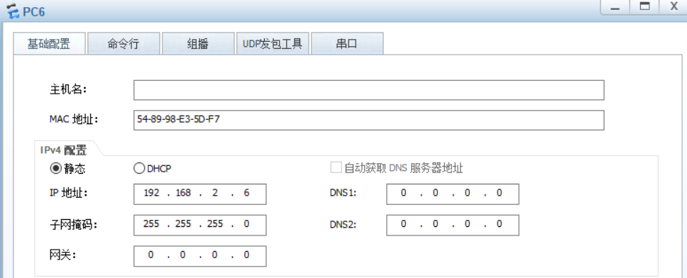
VLAN3 configuration:
[r1]interface g0/0/0.2
[r1-GigabitEthernet0/0/0.2]ip add 192.168.2.254 24
[r1-GigabitEthernet0/0/0.2]dot1q termination vid 3
[r1-GigabitEthernet0/0/0.2]arp broadcast enable
[l1]int g0/0/6
[l1-GigabitEthernet0/0/6]port link-type trunk
[l1-GigabitEthernet0/0/6]port trunk allow-pass vlan all
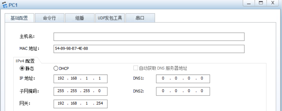
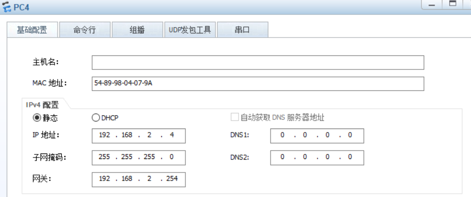
Finally, configure the gateway of each PC.
3, Test:
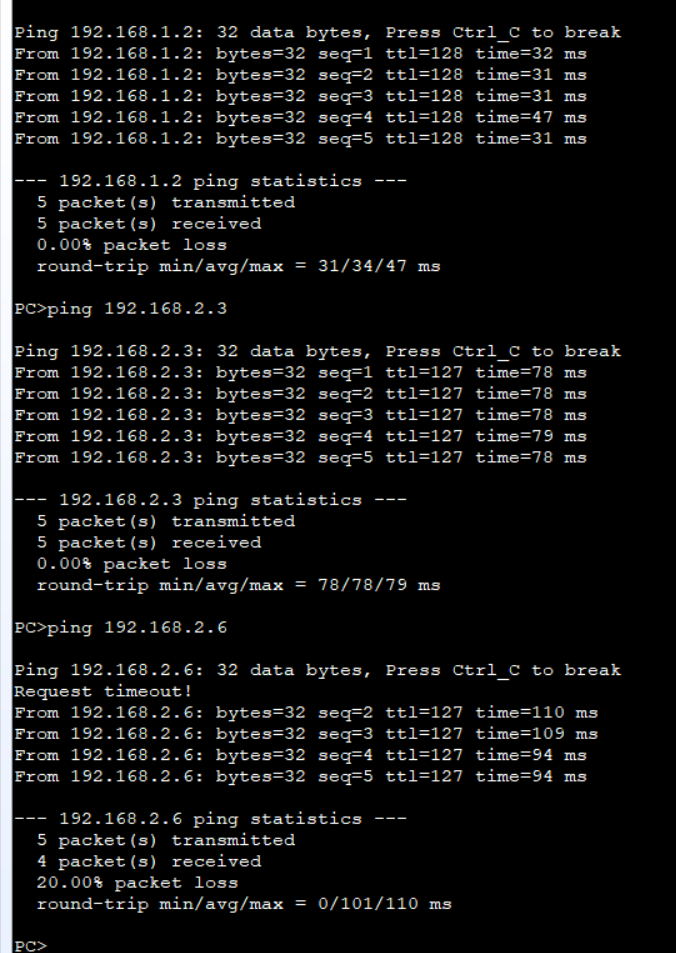
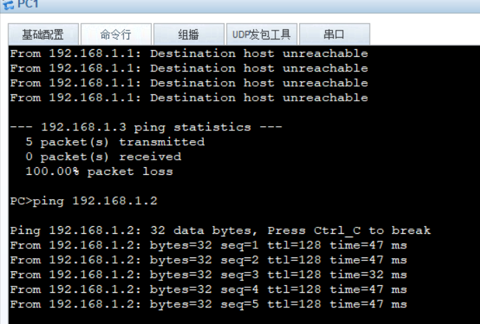
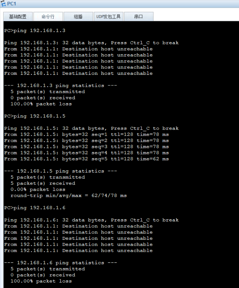
Test with PC1:
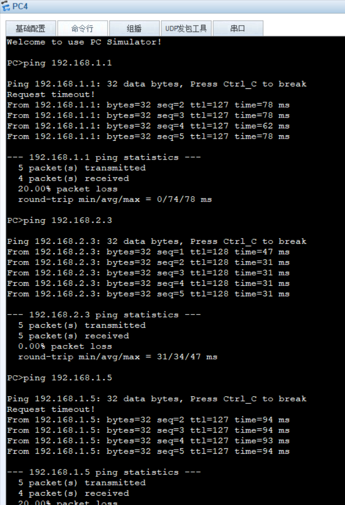
Test with PC5:
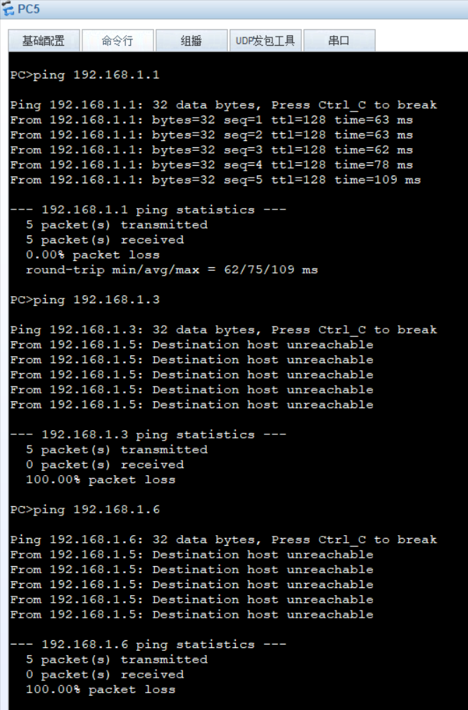
At this time, only the same broadcast domain can communicate.
Modified results: