1. Summary of the day
Low end equipment often solves multi-function, and medium and high-end equipment has special functions
The upper connection is mainly optical fiber, and the lower connection is photoelectric
The essence of down connection is to increase the port density and long distance
The higher up, the better the performance of the equipment
Where is the gateway?
Large: better convergence layer; – Problems in the region will be solved in the region and will not continue to the core
Small: the core layer can also be used
Server: configured at the core layer - the traffic bandwidth is large, and the convergence layer equipment may have insufficient performance
The core switch is used for server access
Default route provincial route nat
MSTP line breaks and switches for 1 to 2 seconds
Layer 3: access, convergence and core
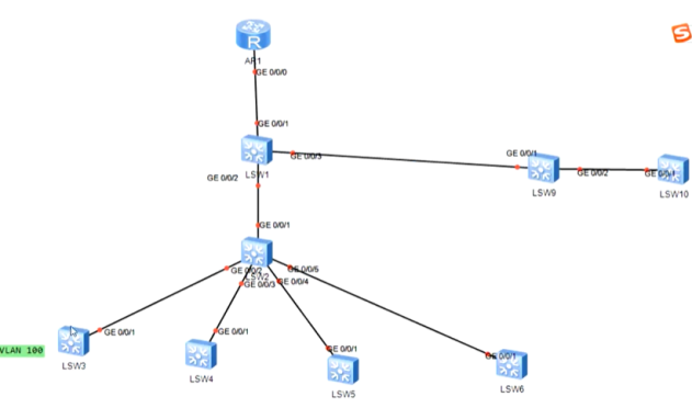
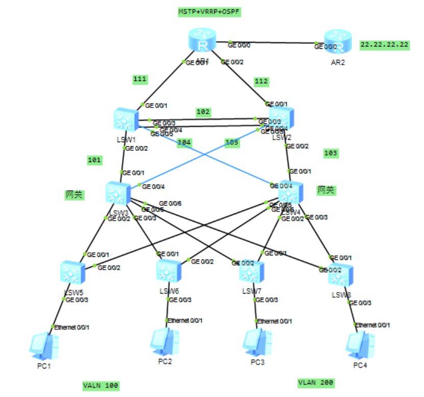
2. Demonstration experiment
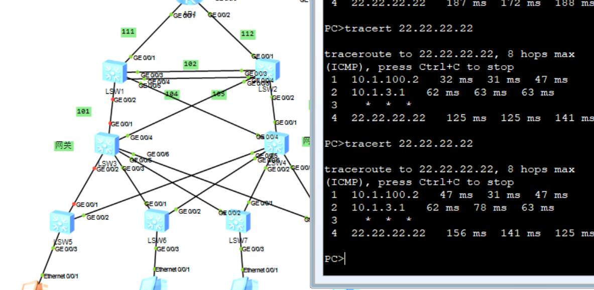
MSTP+VRRP+OSPF comprehensive experiment
As shown in the figure below
Experimental ideas:
1. Access layer (below sw5-sw8)
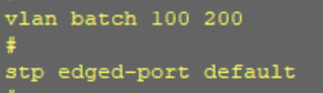
1) The PC interface is configured as access
2) All ports on the switch are set as edge interfaces
interface Ethernet0/0/3
port link-type access
port default vlan 100 (Allow corresponding VLAN adopt PC1,PC2 by VLAN100)
stp edged-port default
Take sw5 as an example:
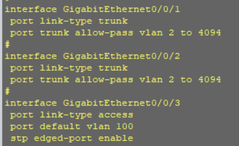
2. Aggregation layer (below sw3-sw4 and above access layer)
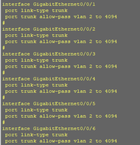
1) Set all interfaces to trunk
interface Ethernet0/0/1
port link-type trunk
port trunk allow-pass vlan all
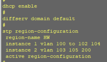
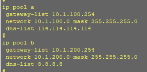
2) Set the gateway at the aggregation layer, configure dhcp pool (sw3 sw4), enable dhcp, and distribute IP addresses
ip pool 100
gateway-list 192.168.100.254
network 192.168.100.0 mask 255.255.255.0
dns-list 114.114.114.114
ip pool 200
gateway-list 192.168.200.254
network 192.168.200.0 mask 255.255.255.0
dns-list 114.114.114.114
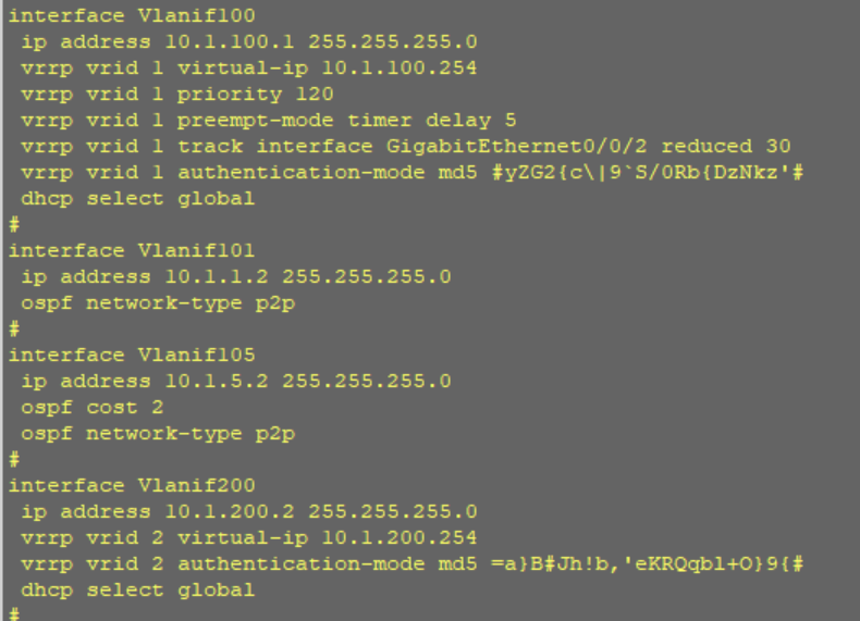
3) Use VRRP to realize gateway redundancy (sw3-sw8 need to be configured)
interface Vlanif100
ip address 192.168.100.1 255.255.255.0
vrrp vrid 1 virtual-ip 192.168.100.254
vrrp vrid 1 priority 120
dhcp select global

interface Vlanif200
ip address 192.168.200.1 255.255.255.0
vrrp vrid 2 virtual-ip 192.168.200.254
vrrp vrid 2 priority 120
dhcp select global
Take sw3 as an example:
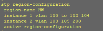
3. Core layer (above sw1-sw2, take SW1 as an example)
1)stp
Except that the interface connecting the router is access, other interfaces can be set to trunk,
Set Ethernet0 / 0 / 3 and Ethernet0 / 0 / 4 to eth trunk, and aggregate links to realize link backup
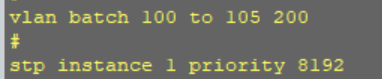
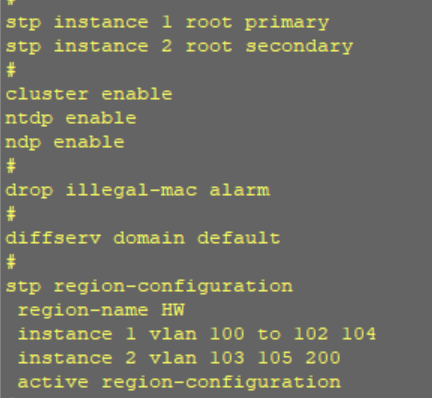
interface Ethernet0/0/3
eth-trunk 0

interface Ethernet0/0/4
eth-trunk 0

interface Eth-Trunk0
port link-type trunk
port trunk allow-pass vlan 2 to 4094

stp region-configuration
region-name 100 Group name. All devices should be in one group
instance 1 vlan 100 101 102 104 Will be a class vlan Put it in an instance
instance 2 vlan 200 103 105
active region-configuration Activate current configuration
Sw1 is the primary root of vlan 100 and sw2 is the primary root of vlan 200 (sw2 is the opposite)
stp instance 1 root secondary
stp instance 2 root primary taproot
Sw3 follows VLAN 100 times and sw4 follows VLAN 200 times
stp instance 1 priority 4096
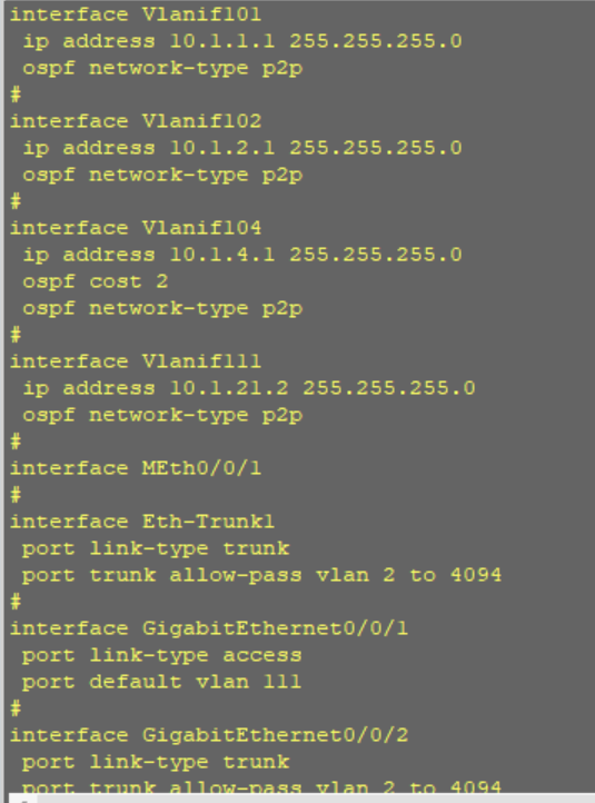
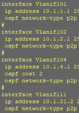
2)svi
Enable svi to realize three-layer interconnection of switches
interface Vlanif101
ip address 10.1.1.1 255.255.255.0

interface Vlanif102
ip address 10.1.2.1 255.255.255.0

interface Vlanif103
ip address 10.1.3.1 255.255.255.0

interface Vlanif111
ip address 10.1.21.2 255.255.255.0
Check whether the spanning tree is normal. You can use cost and priority interference
[sw1]interface GigabitEthernet 0/0/1
[sw1-GigabitEthernet0/0/1]stp instance 1 cost 2
INTEGER<1-200000000> Port path cost

[sw1-GigabitEthernet0/0/1]stp instance 1 port priority ?
INTEGER<0-240> Port priority, in steps of 16
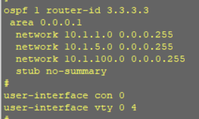
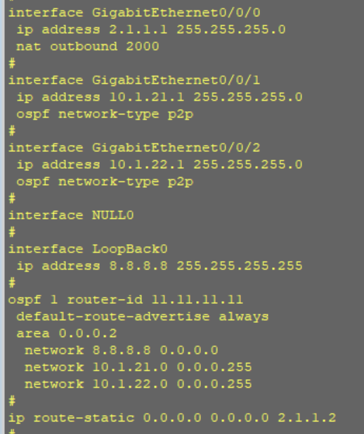
3)ospf
The core is set to region 0 and converged to region 1
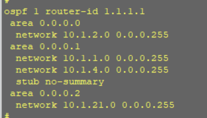
The stub no summary area 1 is set to full stub, and three types of default are published downward
Sw1 and sw2 configure the default to R1
The whole network type of OSPF is set to p2p, and the adjacency relationship is directly formed without DR and BDR elections
#ospf network-type p2p
4) Use nat to access ISP (take R1 as an example)
acl number 2000
rule 5 permit source 192.168.0.0 0.0.255.255

interface GigabitEthernet0/0/2
ip address 10.10.10.1 255.255.255.0
nat outbound 2000

Experimental verification:
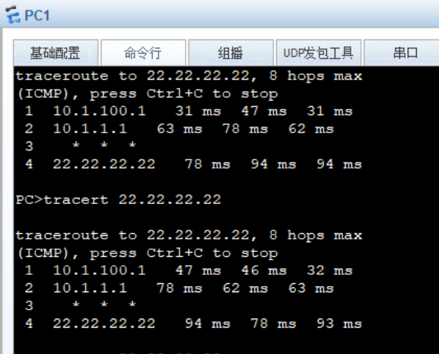
When a line is disconnected, re routing is the best
Experiment completed