Tip: after the article is written, the directory can be generated automatically. Please refer to the help document on the right for how to generate it
preface
At present, I am playing the college students' embedded competition. My responsibility is to develop the Hi3861 development board. Because I used to play more STM32, the generated idea will be implemented on STM32 first and then transferred to the Hi3861 development board. In fact, this is in line with the development process of most Japanese embedded development players.
Tip: the following cases are for reference
1, What is Hi3861?
In fact, hi3861 is not developed by Huawei alone. Hi3861 is Runhe A development board developed by Huawei Hisilicon is a cooperative relationship with them.
Hi3861LV100 is a highly integrated 2.4GHz WiFi SoC chip, which integrates IEEE 802.11b/g/n baseband and and RF circuit. The RF circuit includes power amplifier PA, low noise amplifier LNA, RF balun, antenna switch, power management and other modules; It supports 20MHz standard bandwidth and 5MHz/10MHz narrow bandwidth, and provides a maximum physical layer rate of 72.2Mbit/s.
Hi3861LV100WiFi baseband supports orthogonal frequency division multiplexing (OFDM) technology, is downward compatible with direct sequence spread spectrum (DSSS) and complement keying (CCK) technology, and supports various data rates of IEEE 802.11b/g/n protocol.
Hi3861LV100 chip integrates high-performance 32bit microprocessor, hardware security engine and rich peripheral interfaces, including SPI, UART, I2C, PWM, GPIO and multi-channel ADC, and supports high-speed SDIO2.0
Slave interface, the maximum clock can reach 50MHz; SRAM and Flash are built in the chip, which can run independently, and support and run programs on Flash.
Hi3861LV100 supports Huawei LiteOS and third-party components, and provides an open and easy-to-use development and debugging environment.
Hi3861LV100 chip is applicable to the field of low-power intelligent products of the Internet of things, such as smart appliances, smart door locks, low-power Camera, BUTTON and so on.
2, Use steps
1. Write an STM32 program
First, how does an STM32 program transfer to another board? (this article is Hi3861)
- We need to look at the corresponding pins of the two boards. What this paper transfers is a code for ADC to read the sensor voltage change value. The first thing we need to see is which pins of Hi3861 support ADC function multiplexing, that is, whether we can use this pin to read the voltage value.
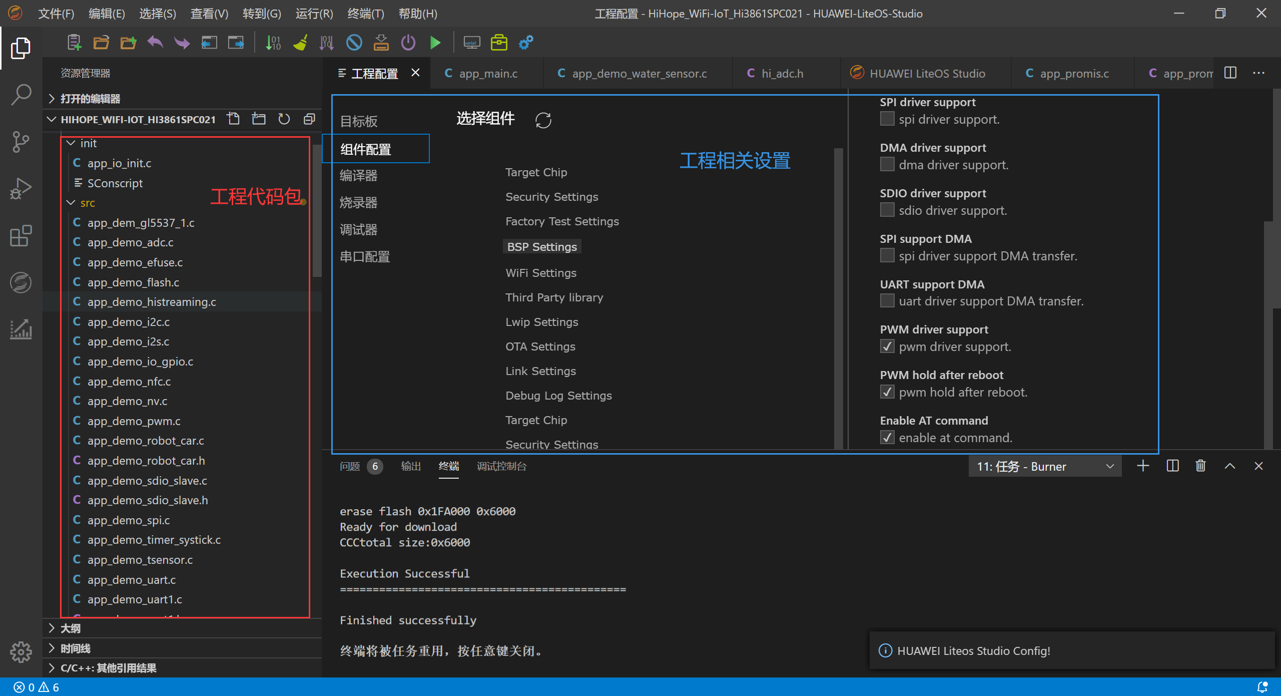
- Secondly, you need to see how to set the second board. For example, STM32 usually needs to guide the package (corresponding system package) and set the magic wand (path path, etc.) to write code. The comparison settings between the two are shown in the following two figures.
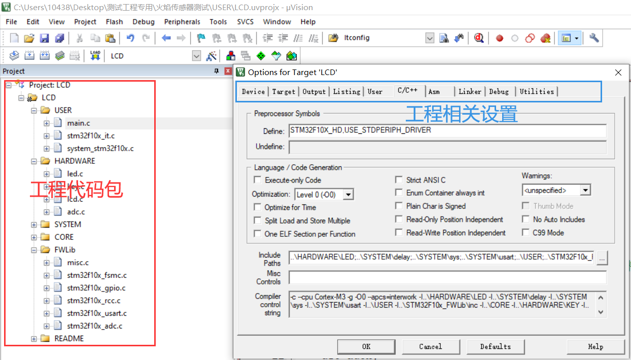
3. When importing the corresponding code package (such as adc.h), it is recommended that Hi3861 be developed directly with an official Hello world routine, which saves a lot of the trouble of importing the package like STM32
4. After the package guide is completed, the library supported by Hi3861 is configured (professional name) BSP (board level support package). This step is very important! This step is very important! This step is very important! If you want to use the corresponding functions of Hi3861, but you don't check the BSP supported, it's useless to write the code correctly! For example, if you want to write an OLED display function, you must check IIC support.
2. How to transfer to Hi3861
After finishing the basic configuration, it is the problem of how to transfer the code. I directly post part of the code analysis. If necessary, go to the end of the article to download the project file
STM32 code is as follows:
int main(void)
 {
    u16 adcx;
	float temp;
	u8 lcd_id[12];			//Store LCD ID string
	delay_init();	    	 //Delay function initialization
	NVIC_PriorityGroupConfig(NVIC_PriorityGroup_2);	 //Set NVIC interrupt packet 2: 2-bit preemption priority and 2-bit response priority
	uart_init(115200);	 	//The serial port is initialized to 115200
 	LED_Init();			     //LED port initialization
   Adc_Init();		  		//ADC initialization
	LCD_Init();
	sprintf((char*)lcd_id,"LCD ID:%04X",lcddev.id);//Print LCD ID to lcd_id array.
   POINT_COLOR=RED;//Set font to red
   LCD_ShowString(60,50,200,16,16,"Elite STM32");
	LCD_ShowString(60,70,200,16,16,"ADC TEST");
	LCD_ShowString(60,90,200,16,16,"ATOM@ALIENTEK");
	LCD_ShowString(60,110,200,16,16,"2015/1/14");
	//Display prompt information
	POINT_COLOR=BLUE;//Set font to blue
	LCD_ShowString(60,130,200,16,16,"ADC_CH0_VAL:");
	LCD_ShowString(60,150,200,16,16,"ADC_CH0_VOL:0.000V");
  	while(1)
	{
      adcx=Get_Adc_Average(ADC_Channel_1,10);
		LCD_ShowxNum(156,130,adcx,4,16,0);//Displays the value of the ADC
		temp=(float)adcx*(3.3/4096);
		adcx=temp;
		LCD_ShowxNum(156,150,adcx,1,16,0);//Display voltage value
		temp-=adcx;
		temp*=1000;
		LCD_ShowxNum(172,150,temp,3,16,0X80);
		LED0=!LED0;
		delay_ms(250);
		LED0=!LED0;
		delay_ms(1000);
	}
}
//The official ADC routine of punctual atoms is directly used here, mainly to transfer ideas. It doesn't matter what code to transfer
The main steps of this code are to initialize the voltage acquisition pin, configure the ADC, get the analog quantity, and then use the function to transfer it to the digital quantity (ADC process) to display it on the LCD. The idea of the code is simple
Hi3861 code is as follows:
#include <hi_early_debug.h>
#include <hi_task.h>
#include <stdio.h>
#include <hi_adc.h>
#include <hi_gpio.h>
#include <hi_io.h>
#include <hi_stdlib.h>
#include <hi_i2c.h>
#include <ssd1306_oled.h>

#define WATER_SENSOR_TASK_SIZE  ( 1024*2 )
#define WATER_SENSOR_TASK_PRIO  ( 28 )
#define ADC_LENGTH         ( 20 )
#define VLT_MIN (100)

hi_u16 g_water_sensor_adc_buf[ADC_LENGTH];

extern hi_u32 oled_init(hi_void);
extern hi_void oled_show_str(hi_u8 x, hi_u8 y, hi_u8 *chr, hi_u8 char_size);
/*
	@berf gpio_config:i2c 0 Pin reuse is I2C mode
*/
hi_void gpio_config() {
    hi_io_set_func(HI_IO_NAME_GPIO_13, HI_IO_FUNC_GPIO_13_I2C0_SDA);
    hi_io_set_func(HI_IO_NAME_GPIO_14, HI_IO_FUNC_GPIO_14_I2C0_SCL);
}
/*
	@berf oled Screen display initialization
	@param hi_void
*/
hi_void water_sensor_display(hi_void)
{
    hi_i2c_init(HI_I2C_IDX_0, HI_I2C_IDX_BAUDRATE); /* baudrate: 400kbps */
    hi_i2c_set_baudrate(HI_I2C_IDX_0, HI_I2C_IDX_BAUDRATE);
    oled_init();

    oled_fill_screen(OLED_CLEAN_SCREEN);//clear screen
}
/*
	gpio init Pin initialization
*/
hi_void water_sensor_gpio_init(hi_void)
{
    hi_io_set_func(HI_IO_NAME_GPIO_7, HI_IO_FUNC_GPIO_7_GPIO);
    hi_gpio_set_dir(HI_GPIO_IDX_7, HI_GPIO_DIR_IN);
}

hi_void *water_sensor(hi_void *param)
{
    hi_u32 ret;
    hi_u16 data;
    float voltage;
    hi_float vlt_max = 0;
    hi_float vlt_min = VLT_MIN;
    hi_u32 i;

    while (1) {
        memset_s(g_water_sensor_adc_buf, sizeof(g_water_sensor_adc_buf), 0x0, sizeof(g_water_sensor_adc_buf));
        for (i = 0; i < ADC_LENGTH; i++) {
            vlt_max =0;
            ret = hi_adc_read(HI_ADC_CHANNEL_3, &data, HI_ADC_EQU_MODEL_4, HI_ADC_CUR_BAIS_DEFAULT, 0xF0); //CHANNAL 3 GPIO 7
            if (ret != HI_ERR_SUCCESS) {
                printf("ADC Read Fail\n");
                return HI_NULL;
            }
            printf("adc original data %d \n", data);
            voltage = (float)data * 1.8 * 4 / 4096.0;  /* vlt * 1.8 * 4 / 4096.0 is to convert codeword to voltage */
            vlt_max = (voltage > vlt_max) ? voltage : vlt_max;
            vlt_min = (voltage < vlt_min) ? voltage : vlt_min;
            printf( "vlt_min:%.3f, vlt_max:%.3f \n", vlt_min, vlt_max );
            if (vlt_max > 1) {
                oled_show_str(0, 4, "is Rainning", 16);/*The test results will be displayed on the screen, if moisture is detected, it will display "it's raining"*/
            } else if (vlt_max < 1) {
                oled_show_str(0, 4, "a sunny day", 16);/*The test results will be displayed on the screen, if no moisture is detected, "sunny" will be displayed"*/
            }
        }
        hi_sleep(100);
    }
}
/*
	@berf Create simulated moisture sensor task
	@param hi_void
	@return Task created successfully ret = HI_ERR_SUCCESS,Failed ret = 0x800xxxx
*/
hi_u32 water_sensor_task(hi_void)
{
    hi_u32 ret;
    hi_task_attr attr ={0};
    hi_u32 water_sensor_id;
    gpio_config();
    /*adc gpio init*/
    water_sensor_gpio_init();
    /*oled display*/
    water_sensor_display();
	/*attr Configuration of structural parameters*/
    attr.stack_size = WATER_SENSOR_TASK_SIZE;//Task stack memory
    attr.task_prio = WATER_SENSOR_TASK_PRIO;//The task priority ranges from 0 to 31. Tasks 0 to 10 should not be used. The SDK has been used. The higher the value, the lower the priority
    attr.task_name = (hi_char*)"water_sensor_task";//task name
	/*create task*/
    ret = hi_task_create(&water_sensor_id, &attr, water_sensor, HI_NULL);
    if (ret != HI_ERR_SUCCESS) {
        printf("Failed to create water_sensor_task\r\n");
    }
    return HI_ERR_SUCCESS;
}
This code is an adc routine written by the official (I'm afraid it's hard to explain what I wrote here)
It can be seen that the biggest difference between Hi3861 and STM32 is that Hi3861 adopts Multithreading STM32 adopts sequential execution mode. Therefore, the normal process of developing Hi3861 is to create a thread task, that is, create task, and then put what needs to be implemented into the function function of thread task jump.
Example: / create task/
ret = hi_task_create(&water_sensor_id, &attr, water_sensor, HI_NULL);
Including water_sensor is a function.
Do not understand the development of multithreaded single chip microcomputer system. Don't tangle with why to write so, learn to use it first! copy sth. without catching its spirit
Iron man said: sometimes try to run before you learn to walk! (that's what I said. I don't remember, probably)
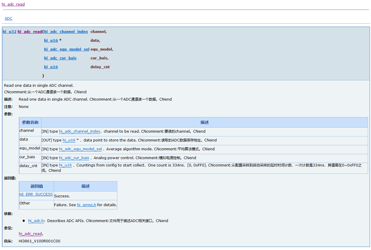
Hi in Hi3861_ adc_ Read function, you need to see API documents and related hardware design documents. Here are some of the pins I have touched that are multiplexed for ADC
1.ret = hi_adc_read(HI_ADC_CHANNEL_3, &data, HI_ADC_EQU_MODEL_4, HI_ADC_CUR_BAIS_DEFAULT, 0xF0); //CHANNAL 3 GPIO 7
2.ret = hi_adc_read(HI_ADC_CHANNEL_2, &data, HI_ADC_EQU_MODEL_4, HI_ADC_CUR_BAIS_DEFAULT, 0); //CHANNAL 2 GPIO 5
3.ret = hi_adc_read(HI_ADC_CHANNEL_5, &data, HI_ADC_EQU_MODEL_4, HI_ADC_CUR_BAIS_DEFAULT, 0xF0); //CHANNAL 5 GPIO 11
The parameter design inside needs to see the API document. I'm ready for you
summary
This paper introduces how to transfer an STM32 program to Hi3861. In fact, this idea is applicable to most transfer development board codes.
Send some projects to you for reference only~
The Internet is too slow to send... Send it in the comment area