Last article This paper introduces the use of LCD screen. This screen also has touch function. This article will introduce the use of LCD touch function.
There are a lot of contents about touch, which are divided into two parts. This part first introduces the preparation of touch driver and printing the coordinates of touch points in real time for testing. First, there is an overall feeling of use. The next article will introduce the specific touch reporting protocol and graphical testing method.
1 touch introduction
The essence of the touch function of LCD is that a transparent touch screen is superimposed on the display screen to realize the interaction with LCD in the way of touch.
The touch screen is divided into resistance touch screen and capacitance touch screen.
- Resistive touch screen is a kind of sensor. Its structure is a structure of film and glass. The adjacent side of the two structures is coated with ITO (a kind of coating with good conductivity and transparency). During the touch operation, the two-layer structure is squeezed and contacted, and the corresponding electrical signal is sent out through the sensor, which is converted into the X and Y values on the screen through operation.
- The Capacity Touch Panel (CTP) works by using the current sensing of the human body. Capacitive screen is a four layer composite glass screen. Capacitive touch screen is a human-computer interaction mode that supports multi-point touch. Ordinary resistive touch screen can only touch a single point.
1.1 hardware schematic diagram
This article uses the 7-inch capacitive touch screen of wildfire, with the same resolution as the screen, 800x480. Touch driver chip GT911 is the chip of IIC interface.
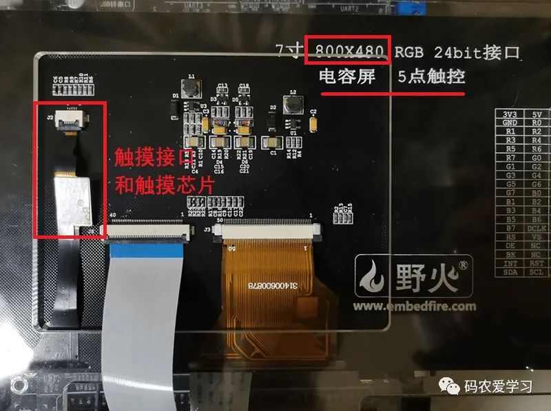
The touch chip has four pins:
- SDA: IIC communication pin of touch chip
- SCL: IIC communication pin of touch chip
- RSTN: reset pin of touch chip
- INT: interrupt pin of touch chip
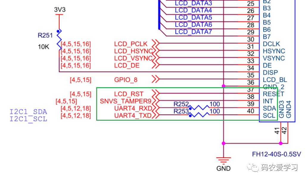
The touch interface corresponding to the board schematic diagram is as follows:
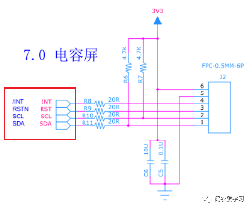
The touch interface corresponding to the screen schematic diagram is as follows:
2 write touch driver code
The touch chip uses IIC communication, reset pin and interrupt pin, so the pin information needs to be configured in the device tree first.
2.1 modifying the equipment tree
Modify imx6ull_myboard.dts file.
Add the pin to be used for touch to iomuxc in the device tree.
Pin | function |
|---|---|
UART4_RX_DATA | Multiplexed to I2C1_SDA, used as SDA pin of IIC1 |
UART4_TX_DATA | Multiplexed to I2C1_SCL, used as SCL pin of IIC1 |
LCD_RST | Multiplexed to GPIO3_IO04 is used as the reset pin of the touch chip |
SNVS_TAMPER9 | Multiplexed to GPIO5_IO09 is used as irq pin of touch chip to receive touch interrupt |
It should be noted that snvs_ The tamper9 pin is multiplexed to GPIO5_IO09, need to add to iomuxc_snvs node.
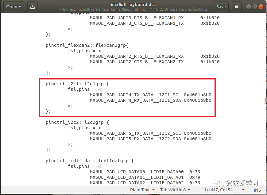
2.1.1 IIC pin
The touch chip uses IIC1. These two pins are added in the device tree and by default without modification:
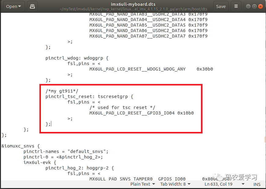
2.1.2 reset pin
&Add to the iomuxc node:
/*my gt911*/
pinctrl_tsc_reset: tscresetgrp {
    fsl,pins = <
        /* used for tsc reset */
        MX6UL_PAD_LCD_RESET__GPIO3_IO04 0x10b0
        >;
};
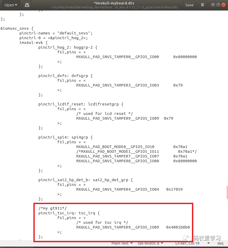
2.1.3 interrupt pin
&iomuxc_ Add to snvs node:
/*my gt911*/
pinctrl_tsc_irq: tsc_irq {
    fsl,pins = <
        /* used for tsc irq */
        MX6ULL_PAD_SNVS_TAMPER9__GPIO5_IO09   0x4001b8b0
        >;
}
2.1.4 adding GT911 to IIC equipment
The GT911 touch driver is attached to the IIC1 bus as an IIC device. Find the IIC1 node:
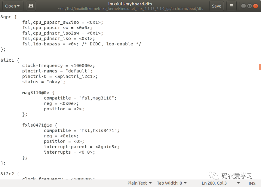
Corresponding child nodes need to be added under the IIC1 device node:
gt911_tsc@5d {
    compatible = "goodix,gt911";
	reg = <0x5d>;
    pinctrl-0 = <&pinctrl_tsc_reset>;
    pinctrl-1 = <&pinctrl_tsc_irq>;
    reset-gpios = <&gpio3 4 GPIO_ACTIVE_LOW>;
    irq-gpios = <&gpio5 9 GPIO_ACTIVE_HIGH>;
    interrupt-parent = <&gpio5>;
    interrupts = <9 IRQ_TYPE_EDGE_FALLING>;
};
After modification:
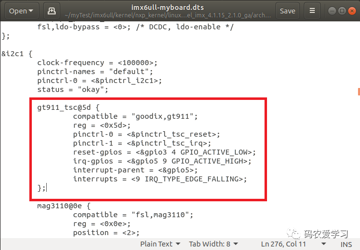
`Reg = < 0x5d > is the address of GT911 touch chip on IIC1 bus.
2.2 touch chip data register
Check the data manual of GT911 and find the table related to registers:

Mainly focus on the following registers, which are used to read the touch coordinate points:
Addr | Access | bit7~bit0 |
|---|---|---|
0x814E | R/W | buffer status(7) large detect(6) Reserved(5~4) number of touch points(3~0) |
0x814F | R | track id |
0x8150 | R | point 1 x coordinate (low byte) |
0x8151 | R | point 1 x coordinate (high byte) |
0x8152 | R | point 1 y coordinate (low byte) |
0x8153 | R | point 1 y coorte (high byte) |
0x8154 | R | Point 1 size (low byte) |
0x8155 | R | Point 1 size (high byte) |
0x8156 | R | Reserved |
0x8157 | R | track id |
... | ... | ... |
0x815F | R | track id |
... | ... | ... |
0x8167 | R | track id |
... | ... | ... |
0x816F | R | track id |
0x8170 | R | point 5 x coordinate (low byte) |
0x8171 | R | point 5 x coordinate (high byte) |
0x8172 | R | point 5 y coordinate (low byte) |
0x8173 | R | point 5 y coordinate (high byte) |
0x8174 | R | Point 5 size (low byte) |
0x8175 | R | Point 5 size (high byte) |
0x8176 | R | Reserved |
- 0x814E: this register is very important. It is a readable and writable register. By reading this register, you can know whether there are currently touch points (represented by the highest bit) and how many touch points (represented by the lower 3 bits)
- 0x814F~0x8156: coordinate data of the first group of touch
- 0x814F: is the tracking id of the touch point. The GT911 supports 5-point touch. The value of id here is 0 ~ 4
- 0x8150: X coordinate of touch point 1 (low byte)
- 0x8151: X coordinate (high byte) y of touch point 1
- 0x8152: y coordinate of touch point 1 (low byte)
- 0x8153: y coordinate of touch point 1 (high byte)
- 0x8154~0x8156: not used temporarily
- Registers after 0x8157: similar to the meaning of the first group of touched coordinate data, one has five groups
Note: GT911 supports hardware tracking of touch points, so a track id is provided for each touch point. For example, when five fingers touch the screen in turn, the track id in the five groups of coordinate registers will be 0, 1, 2, 3 and 4 in turn. When the first finger is released, that is, the point with track id 0 is gone. At this time, the five groups of coordinate registers, Yes, only the first 45 sets of coordinate registers have data, and the track id will be 1, 2, 3 and 4 in turn (it's important to understand this, because I took it for granted that when I moved the first finger, there was no data in the first set of coordinate registers)
2.3 writing drivers
New gt911 C file as driver file
The use of touch chip GT911 essentially uses IIC communication to read and write data, because the driver of touch screen is actually IIC driver. In addition, the touch data is triggered by interrupt, so the writing of touch driver involves interrupt processing. In case of interruption, after reading the touch data, it should be transferred to the application layer. Here, the input subsystem of Linux is used (this is also a way of software layered design of Linux).
Therefore, writing a touch driver mainly involves three points:
- IIC protocol driver
- Interrupt processing (obtaining touch data)
- input subsystem (transfer touch data to application layer)
2.3.1 IIC Driver Architecture
The drive of GT911 is written according to IIC drive. When the drive is running, GT911 will run automatically_ Probe, various initialization operations will be performed in this function. In addition, pay attention to the matching list. The "goodix,gt911" here corresponds to the device node added in the device tree. The names of the two places should be consistent.
/* Match list */
static const struct of_device_id gt911_of_match[] = {
    {.compatible = "goodix,gt911"},
    {/* Sentinel */}
};

/* i2c Drive structure */
struct i2c_driver gt911_i2c_driver = {
    .driver = {
        .owner = THIS_MODULE,
        .name = "gt911",   /* The driver name is used to match the device. It is applicable when there is no device tree*/
        .of_match_table =gt911_of_match,  /* Device tree matching list */
    },
    .probe =gt911_probe,
    .remove =gt911_remove,
    .id_table = gt911_id, /* id Configuration list */
};
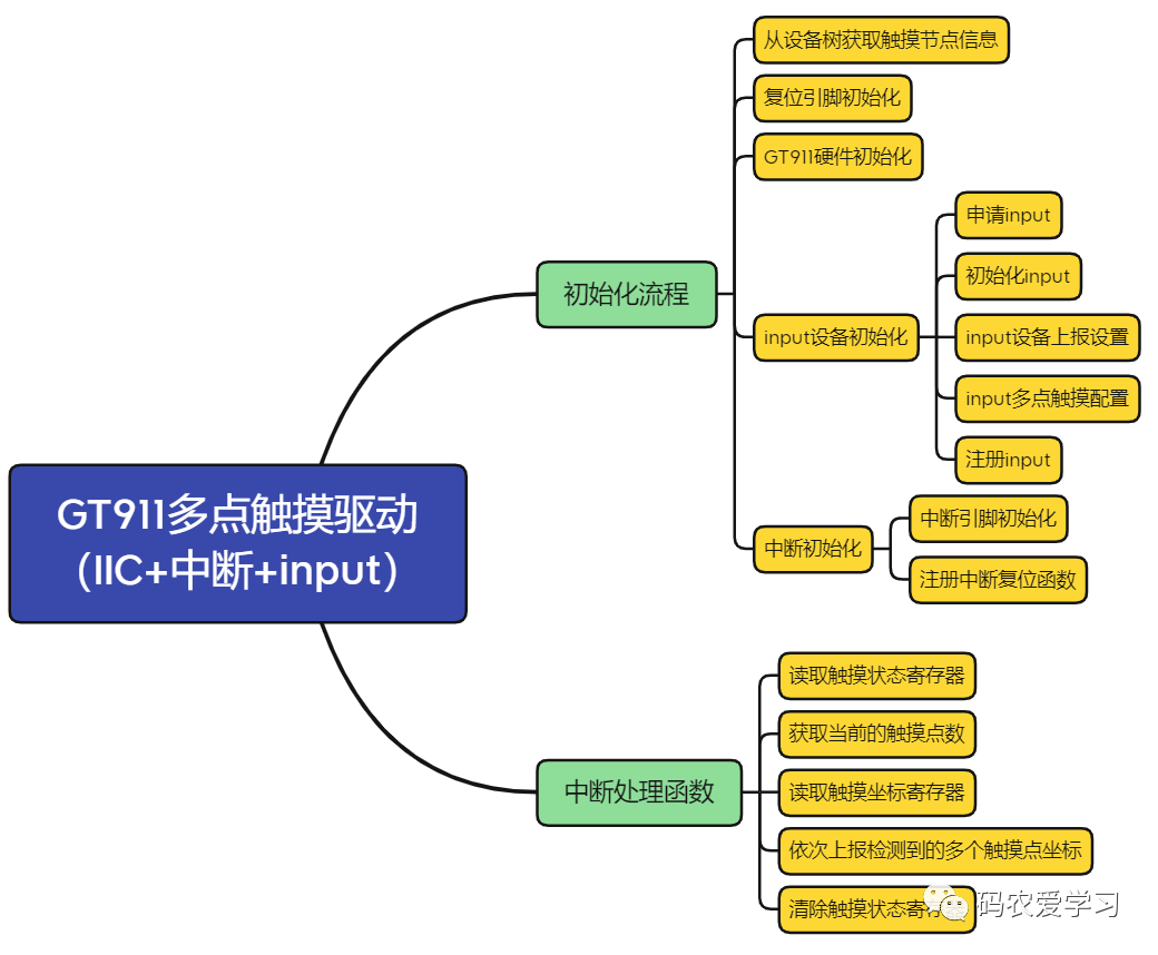
2.3.2 driver initialization process
gt911_ The probe function initializes the touch driver. The basic process is to obtain the touch node from the device tree, and then initialize IO, interrupt and reset, and touch devices.
static int gt911_probe(struct i2c_client *client, const struct i2c_device_id *id)
{
u8 ret = 0;
gt911.client = client;
printk("[BSP] gt911 driver and device has match!\r\n");
/* Gets the interrupt and reset pins in the device tree */
printk("[BSP] get gpios\r\n");
gt911.irq_pin = of_get_named_gpio(client->dev.of_node, "irq-gpios", 0);
gt911.reset_pin = of_get_named_gpio(client->dev.of_node, "reset-gpios", 0);
/* Initialization reset pin */
ret = gt911_ts_reset(client, >911);
/* Initialize gt911 */
printk("[BSP] init gt911\r\n");
gt911_write_reg(>911, GT_CTRL_REG, 2); /* Soft reset */
mdelay(100);
gt911_write_reg(>911, GT_CTRL_REG, 0); /* Stop soft reset */
mdelay(100);
/* input Register device*/
printk("[BSP] init input device\r\n");
gt911.input = devm_input_allocate_device(&client->dev);
/* Initialize input */
gt911.input->name = client->name;
gt911.input->id.bustype = BUS_I2C;
gt911.input->dev.parent = &client->dev;
/* Set the events to be reported by the input device*/
__set_bit(EV_SYN, gt911.input->evbit);
__set_bit(EV_KEY, gt911.input->evbit); /* Key event */
__set_bit(EV_ABS, gt911.input->evbit); /* Repeat event */
/* Set which keys the input device needs to report*/
__set_bit(BTN_TOUCH, gt911.input->keybit); /* Touch value */
/* Multi touch */
input_mt_init_slots(gt911.input, MAX_SUPPORT_POINTS, 0); /*Number of touch points */
input_set_abs_params(gt911.input, ABS_MT_POSITION_X,0, 800, 0, 0);
input_set_abs_params(gt911.input, ABS_MT_POSITION_Y,0, 480, 0, 0);
/* Register input */
ret = input_register_device(gt911.input);
/* Last initialization interrupt */
ret = gt911_ts_irq(client, >911);
printk("[BSP] %s done \r\n",__FUNCTION__);
return 0;
}
2.3.3 initialization of reset and interrupt
The initialization of reset pin is mainly to pull down and then pull up the reset pin to realize reset. The main contents are as follows:
/* Request to reset IO and default output high level */
devm_gpio_request_one(&client->dev,
                      dev->reset_pin,
                      GPIOF_OUT_INIT_HIGH,
                      "gt911 reset");

gpio_set_value(dev->reset_pin, 0);  /* reset */
msleep(10);
gpio_set_value(dev->reset_pin, 1);  /* Stop reset */
msleep(300);
Interrupt initialization, including IO application and interrupt function registration:
/* Request reset IO */
devm_gpio_request_one(&client->dev,
dev->irq_pin,
GPIOF_IN,
"gt911 irq");
/* Application interruption */
devm_request_threaded_irq(&client->dev,
client->irq,
NULL,
gt911_irq_handler, /* Interrupt handling function */
IRQF_TRIGGER_FALLING | IRQF_ONESHOT, /* Trigger mode */
client->name,
>911);
2.3.4 interrupt processing function
Only gt911 is posted here_ irq_ The main content and basic idea of handler is to read * * 0x814E (GT_GSTID_REG) * * register first, judge the number of touch points, and then read the corresponding coordinate point data register and report the data in turn.
/* -----Read touch information register----- */
ret = gt911_read_regs(dev, GT_GSTID_REG, &data, 1);
if(data == 0x00) /* No touch data*/
{
    goto fail;
}
else
{  /* Statistics touch information */
    status       = data >> 7;          // bit7:1 indicates that the coordinates (or keys) are ready, and the master can read. 0 indicates that they are not ready, and the data is invalid
    large_detect = (data >> 6) & 0x01; // bit6:
    touch_num    = data & 0x0f;        // bit3~0: number of coordinate points on the screen
}

if(touch_num) /* Touch press */
{
    /* -----Read the specific touch point data register----- */
    gt911_read_regs(dev, GT_TP1_REG, buf, BUFFER_SIZE);
    id = buf[0]; // id of the first touch point in the data
    touch_index |= (0x01<<id);

    /* Report the coordinates of each touch point */
    for (i = 0; i < 5; i++)
    {
        if ((touch_index & (0x01<<i)))
        {
            input_x = (buf[pos + 1] | (buf[pos + 2] << 8)) & 0x0fff;  // x coordinate
            input_y = (buf[pos + 3] | (buf[pos + 4] << 8)) & 0x0fff;  // y coordinate

            input_mt_slot (dev->input, id); // ABS generation_ MT_ The coordinates of which touch point is the slot event report
            input_mt_report_slot_state(dev->input, MT_TOOL_FINGER, true);   // Designated finger touch continuous touch
            input_report_abs(dev->input, ABS_MT_POSITION_X, input_x);   // Reporting touch point coordinate information
            input_report_abs(dev->input, ABS_MT_POSITION_Y, input_y);   // Reporting touch point coordinate information
            printk("[%d](%d, %d) ", id, input_x, input_y);

            report_num++;
            if (report_num < touch_num)
            {
                pos += 8;
                id = buf[pos];
                touch_index |= (0x01<<id);
            }
        }
        else
        {
            input_mt_slot(dev->input, i);
            input_mt_report_slot_state(dev->input, MT_TOOL_FINGER, false);   // Turn off finger touch
        }
    }
    printk("\r\n");
}
else if(last_index)/* Touch release */
{
    for (i = 0; i < 5; i++)
    {
        if ((last_index & (0x01<<i)))
        {
            input_mt_slot(dev->input, i); /* Report touch points */
            input_mt_report_slot_state(dev->input, MT_TOOL_FINGER, false); // Turn off finger touch
        }
    }
}
last_index = touch_index;

input_mt_report_pointer_emulation(dev->input, true);
input_sync(dev->input);   /* Synchronization data reporting completed */

data = 0x00;  /* Write 0 to 0x814E register, otherwise it will always enter interrupt */
gt911_write_regs(dev, GT_GSTID_REG, &data, 1);   //write in
Summarize the execution process of GT911 multi touch drive:
3. Use the driver of Linux kernel (not tested)
For the touch screen driver, NXP has written the touch driver, which can be modified and used on its own board.
But I didn't succeed in the test. I'll do it later, so I can skip this part.
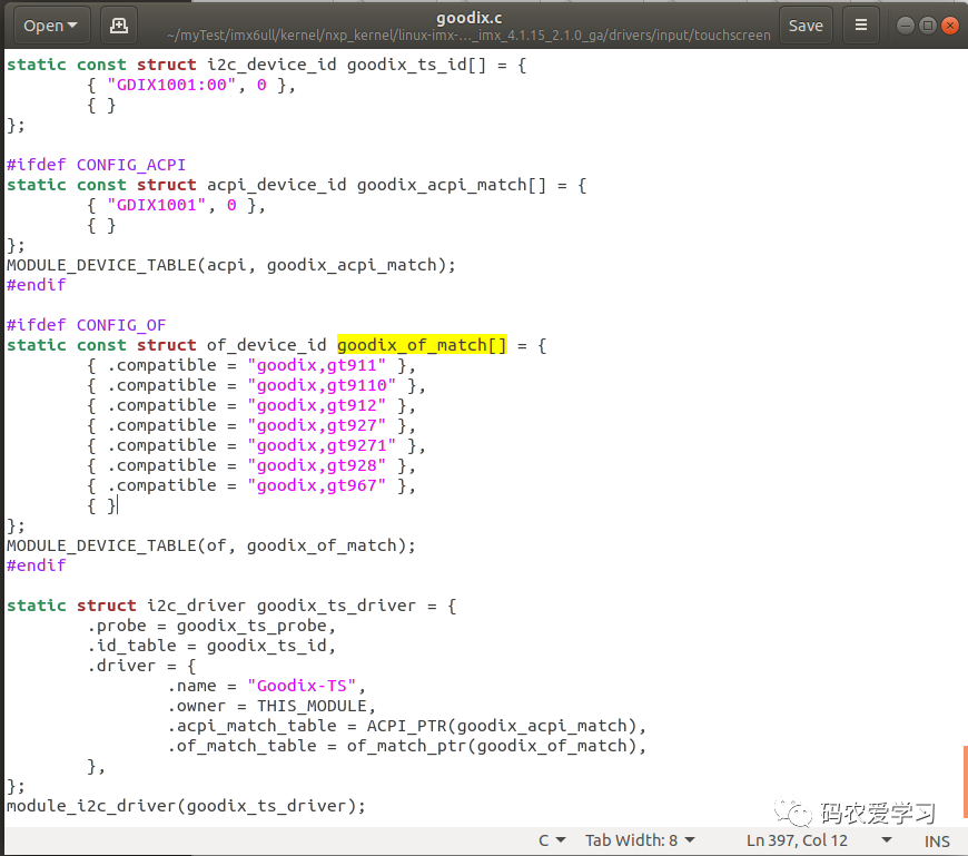
The driver model of my 7-inch screen is GT911, which belongs to the touch chip produced by GOODIX company. The touch driver has been added to the Linux kernel by default, located at: / Drivers / input / Touchscreen / GOODIX c.
Using the Linux kernel self generation driver, you also need to configure the kernel. In the Linux kernel source directory, enter the following command to open the graphical configuration of the kernel:
make ARCH=arm CROSS_COMPILE=arm-linux-gnueabihf- menuconfig
Reach the Linux kernel configuration interface, and then press the path to find the corresponding configuration item:
-> Device Drivers
	-> Input device support
		-> Touchscreens (INPUT_TOUCHSCREEN [=y])
			<*>   Goodix I2C touchscreen
Finally arrive at this interface:
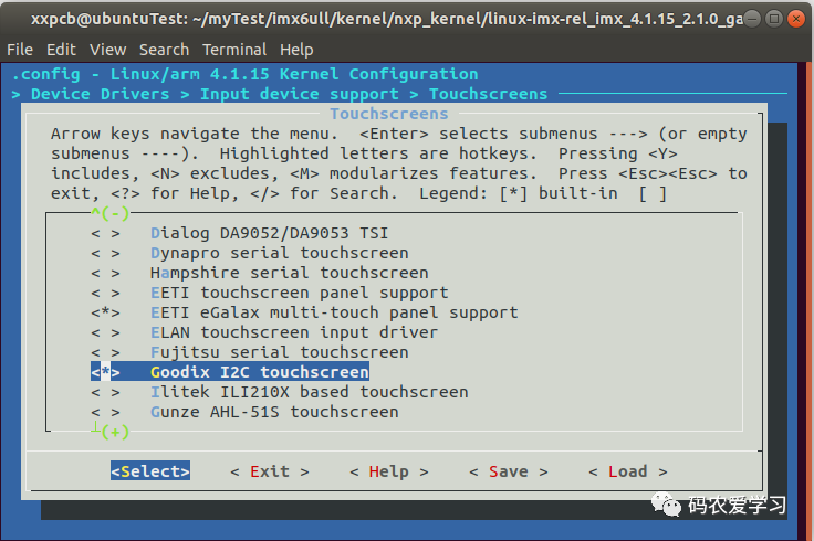
Press y to check the asterisk, press ESC repeatedly to exit, and finally prompt to save. Press y to save the configuration.
Then you need to recompile the zImage and device tree, go to the Linux kernel source directory, and execute the previous compilation script
./build_myboard.sh
When compiling, the Linux graphical configuration interface will pop up. There is no need to make any configuration. Directly press ESC twice to exit the graphical interface
Compile zImage (arch/arm/boot directory) and imx6ull myboard Copy DTB (arch/arm/boot / DTS directory) to the network boot location
cp arch/arm/boot/zImage ~/myTest/tftpboot/nxp/
cp arch/arm/boot/dts/imx6ull-myboard.dtb ~/myTest/tftpboot/nxp/
4 touch test
Use your own touch driver to test.
4.1 compiling device tree
First, compile the device tree, verify whether the added touch node works normally, execute the following command in the Linux kernel source code directory, recompile the device tree and copy it to the network startup location.
make imx6ull-myboard.dtb
cp arch/arm/boot/dts/imx6ull-myboard.dtb ~/myTest/tftpboot/nxp/
Then restart the development board. You can first go to the following location to check whether the nodes of the device tree are normal:
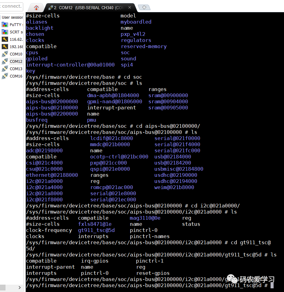
4.2 compiling driver files
Then compile the driver file, that is, gt911 c. The compilation method is the same as before, and Makefile is used for cross compilation in ubuntu.
The corresponding touch application program is not used in this article. All touch coordinate printing is carried out through printk in the driver.
After compiling the driver, the corresponding Copy the ko file to the board.
4.3 coordinate output of test touch point
First load the touch driver, and the serial port will print the event assigned to the touch. Here is event2.
Then execute the following command for touch test:
hexdump /dev/input/event2
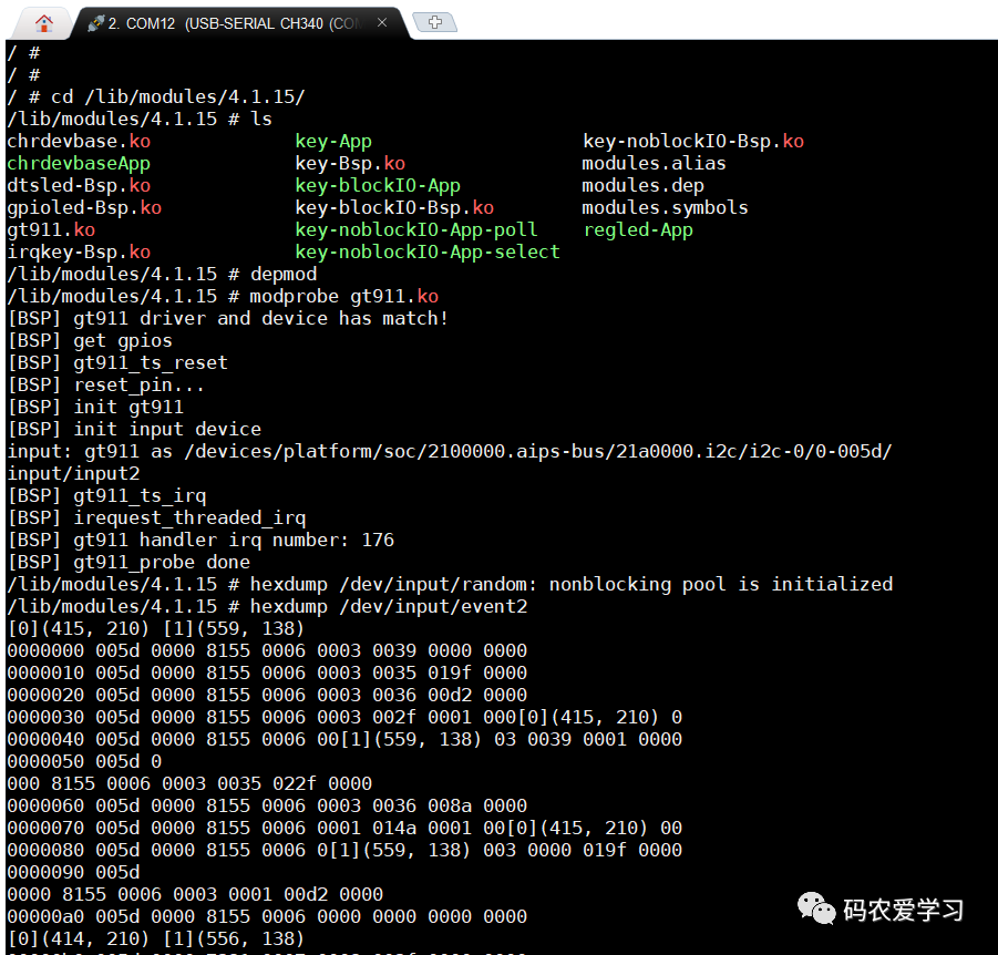
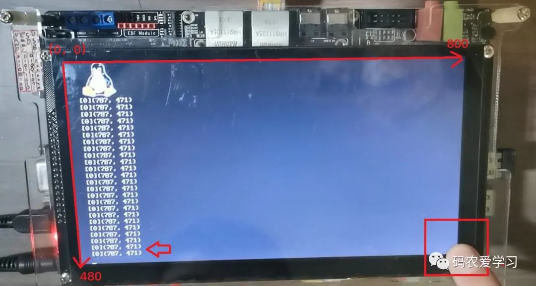
When you put your finger on the screen, you can see the printing of coordinate values on the LCD screen. For example, if you put your finger on the lower left corner of the screen, the corresponding output value is roughly the maximum position of the screen (800480):
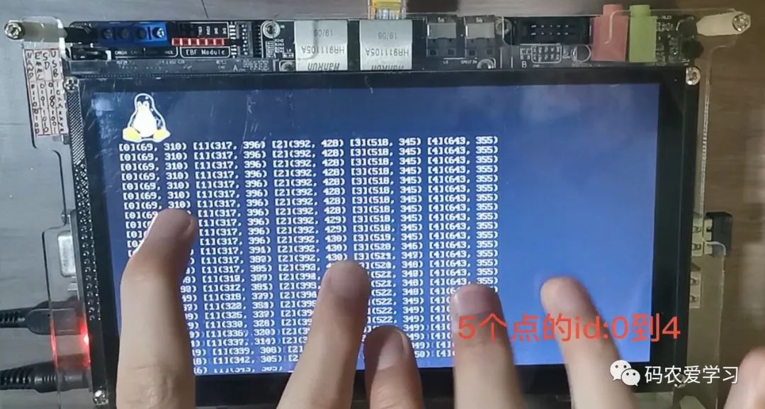
GT911 supports multi touch. The driver also obtains and prints multi-point data. When multiple fingers are placed on the screen, you can see the coordinate printing of up to 5 touch points:
5 Summary
This paper mainly introduces the driver writing and use of multi touch chip GT911, and tests the touch function by printing the touch point in real time.