I2C bus is a serial bus developed by Philips. All devices share two signal lines to realize data transmission.
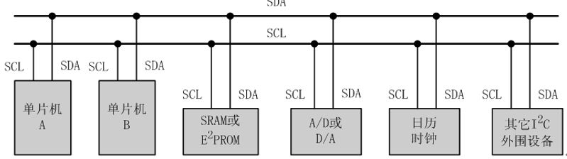
The bus interface is connected with a pull-up resistor and defaults to a high level, so a starting signal can be marked with "when a low level appears". I personally imagine it as: many people in different rooms (devices) on a corridor, all of them open the door and connect two long receivers (the kind they played when they were young), and each of them connects one of the two main lines to his own room. Both receivers are usually quiet (1). If someone in a room calls (0), the rest of us will know that we are ready to start talking.
In order to ensure order, one person was chosen as the leader, who led the process of the call. This is the host of the bus, and the others are slaves. There are many slaves and only one host.
Two signal lines, one is called SDA and the other is SCL. As the name implies, data lines are used to transmit data, and clock lines are used to manage order.
How to express the beginning, how to express the end, with the following chart. Attention should be paid to strict time regulations.
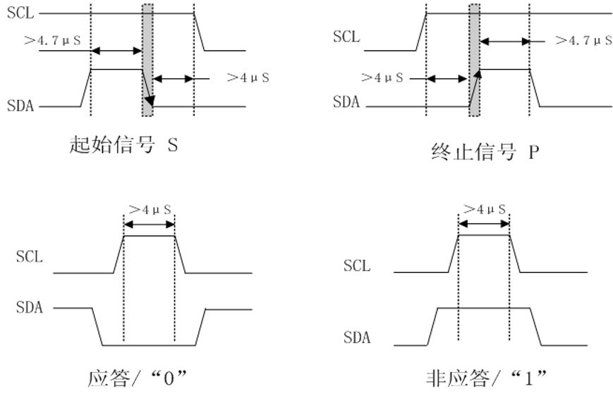
First of all, we know how to call the beginning and end (start and stop signals). Then, specify how the answer is "yes" and "no" (response and non-response).
Next, we need to know who is calling to whom, so we need to give each room a name, that is, an address. Then use a 0 or 1 to indicate the direction, from whom to whom.
Therefore, the process of data transmission, in general, is like this: the leader shouted "start", said a room name, at the same time, all the people in the room to confirm whether it is their own. The leader indicated his purpose, saying whether to transmit data to him or read data from him, and then, confirming that the team member in his room had responded, he could start transmitting data. Upon completion, the host/slave gives a response indicating whether it has been received or not.
The following is the data format transmitted on SDA.
(a) Host sends data to slave

S represents the starting signal. Shadows indicate that the host sends. A means a response, and underlined means a non-response. P means stop.
(b) After the host transmits the data, it reads the data from the slave machine.

(c) To change direction during transmission
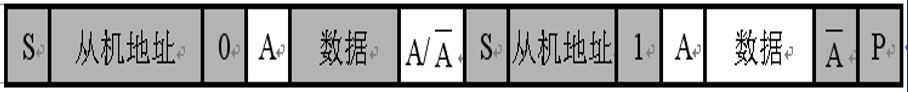
The method is to repeat the starting signal and slave address once and add a direction bit to change the direction.
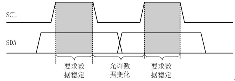
SCL is used to manage order. As long as the SCL remains at a high level, the data being transmitted by SDA can not be chaotic, and SDA can only change if it is lowered. This ensures that the data transmission will not be disorderly, so in the actual transmission process, SCL will continue to flip.
In addition, if there are many identical devices, how to distinguish them? The method is to fix the first few bits, which means that they are the same device, while the latter ones are movable (programmable). If there are three bits left behind, then there are eight programmable devices, that is to say, eight of the same devices are allowed to connect to the bus. The front address is called "device address" and the back address is called "head address". Therefore, every master-slave communication, the device address, plus direction bit, and other device response should be transmitted first, and then the head address to find a specific device, plus direction bit, waiting for it to respond. Then the data transmission begins.
Writing process:

Readout process:

The following is a commentary on some key functions of I2C bus simulation.
//Delay 10 microsecond function
void Delay10us(void)
{
	unsigned char a,b;
	for (b=1;b>0;b--)
		for (a=2;a>0;a--)
			;
}

//I2C start signal simulation
void I2cStart()
{
	SDA = 1;
	Delay10us();
	SCL =1;
	Delay10us();
	SDA = 0;
	Delay10us();
	SCL =0;
	Delay10us();

}

//I2C Stop Signal Simulation
void I2cStop()
{
	SDA = 0;
	Delay10us();
	SCL =1;
	Delay10us();
	SDA = 1;
	Delay10us();

}

//I2C Send Data Function
unsigned char I2cSendByte(unsigned char dat)
{
	unsigned char a = 0,b;
	for(a=0;a<8;a++)	   //Bit-by-bit transmission of data
	{
		SDA = dat>>7;	   //Move 7 bits to the right and send the highest bit to SDA
		dat = dat<<1;	   //Move one to the left and the next to the highest.
		Delay10us();
		SCL = 1;
		Delay10us();
		SCL = 0;	//Flip SCL, SCL for low-level data transmission can be changed
		Delay10us();
	}
	SDA = 1;
	Delay10us();
	SCL = 1;	   //Release data line and clock line
	while(SDA)	   //Waiting for slave reply, SDA lowers jump-out cycle if reply
	{
	 	b++;	   //Failure without response for a period of time
		if(b>200)
			{
				SCL = 0;
				Delay10us();
				return 0;	//Data transmission failure
			}
	}
	SCL = 0;
	Delay10us();
	return 1;	 //Successful data transmission

}

//I2C Read Data Function
unsigned char I2cReadByte()
{
 	unsigned char a = 0;
	SDA = 1;	//Pull up the data line and keep idle waiting for data
	for(a=0;a<8;a++)	//One Bit Read Data
	{
		SCL = 1;	 //Pull up the clock line to keep data stable and ready to receive
		Delay10us();
		dat<<=1;		//Move one to the left and empty one to read the data.
		dat |= SDA;		//Or operation, dat empty bit is 0, for example, SDA is 0, SDA is 1, which is equivalent to saving SDA data.
		Delay10us();
		SCL = 0;		//Flip the clock line so that the lower data can be changed
		Delay10us();
	}
	return dat;	   	//Returns read data
}

//Writing Data Function to At24C02 Chip
void At24c02Write(unsigned char addr,unsigned char dat)
{
 	I2cStart();		//Initial signal
	I2cSendByte(0xa0);	  	//Sender Address (Fixed)
	I2cSendByte(addr);		//Send Head Address (Self-defined)
	I2cSendByte(dat);		//send data
	I2cStop();		//Stop signal

}

//Read Data Function
unsigned char At24c02Read(unsigned char addr)
{
	unsigned char num;
	I2cStart();		//Initial signal
	I2cSendByte(0xa0);	  	//Sender Address (Fixed)
	I2cSendByte(addr);		//Send Head Address (Self-defined)

	I2cStart();				//Add a starting signal to change the direction of data transmission
	I2cSendByte(0xa1);		//Read device address, last bit indicates direction
	num = I2cReadByte();	//Save read data
	I2cStop();		//Stop signal

	return num;
}