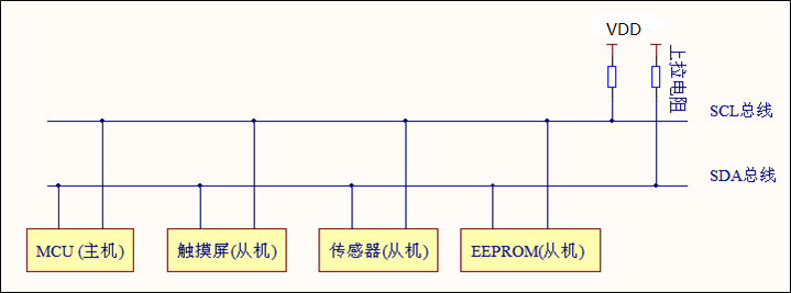
1, Basic characteristics of IIC
Two line communication: data line (SDA) and clock line (SCL).
Iic can mount multiple devices, including master and slave (host access slave). All devices on IIC bus have a unique device address, and the host determines the corresponding slave through the device address.
IIC adopts half duplex communication, and the hardware needs pull-up resistance is generally 4.7K~10K, and the typical value is 4.7K. The maximum capacitance on the bus is limited to 400pF.
2, IIC communication sequence
IIC is high when idle.
Master writes data to slave
Start and stop signals
Start signal: when SCL is high level, SDA changes from high to low
Stop signal: when SCL is high power level, SDA changes from low to high
void I2C_Start(void)   //Start signal function
{
 SDA_Out(1);   //SDA output high
 SCL_Out(1);   //SCL output high
 delay_us(5);
 SDA_Out(0);   //SDA output low
 delay_us(5);
 SCL_Out(0);
 delay_us(3);
}
void I2c_Stop(void)   //Stop signal function
{
 SDA_Out(0);    //SDA output low
 SCL_Out(0);    //SCL output low
 delay_us(5);
 SCL_Out(1);    //SCL output high
 delay_us(5);
 SDA_Out(1);
 delay_us(3);
}
Data changes can only be made when SCl is low
****Host sends data to slave****

The shadow part is the data sent by the host to the slave, and the blank part is the data returned by the slave.
The host sends first: start signal + slave address [high 7bit is the address, and the lowest bit is read / write bit (0: write to the slave; 1: read to the slave)] + read ACK (send from the slave to the host) + write data + read ACK + +Write data + read ACK + stop signal.
The ACK from the master to the slave is sent from the slave to the master.
Host receives data to slave
The shadow part is the data sent by the host to the slave, and the blank part is the data returned by the slave.
The host sends first: start signal + slave address [high 7bit is the address, and the lowest bit is read / write bit (0: write to the slave; 1: read to the slave)] + read ACK (send from the slave to the host) + read data + Write ACK + +Read data + Write ACK + stop signal.
ACK summary: ack is sent by data receiver to data transmitter.
void Ack(void)  //Host read ACK
{
    SCL_Out(0);
    delay_us(2);
 SDA_Out(1);
 SDA_IN();
 delay_us(2);
 SCL_Out(1);
 SDA_Out(GPIO_ReadInputDataBit(GPIOB,GPIO_Pin_7));
    delay_us(4);
 SCL_Out(0);
    SDA_OUT();
 delay_us(2);
}
void Nack(uint8_t ack)  //Host writes ACK
{
 SCL_Out(0);
 delay_us(2);
 if(ack == 1)
    SDA_Out(1);
 else
   SDA_Out(0); //Write reply signal
  delay_us(2);
  SCL_Out(1);                    //Pull up the clock line
  delay_us(4);                 //delayed
  SCL_Out(0);                   //Pull down the clock line
  delay_us(2);                 //delayed

}
The host uses Ack function to send data, Nack function to receive data, and the last Nack is high
void I2c_SendByte(uint8_t _ucByte)  //Host sends 8bit data
{
  uint8_t i;
  for (i = 0; i < 8; i++)
 {
   if (_ucByte & 0x80)
    SDA_Out(1);
  else
    SDA_Out(0);
 delay_us(2);
  SCL_Out(1);
  delay_us(2);
  _ucByte <<= 1;   //Move one bit left
  SCL_Out(0);
 }
 SDA_Out(0);
 delay_us(1);
 SCL_Out(0);
 delay_us(1);
}
uint8_t I2c_ReadByte(void)    //Host receives 8bit data
{
  uint8_t i;
  uint8_t value;
  /* Read bit7 with the first bit as data */
 value = 0;
 for (i = 0; i < 8; i++)
 {
  value<<=1;
  SCL_Out(0);
  SDA_IN();
  delay_us(2);
  if(GPIO_ReadInputDataBit(GPIOB,GPIO_Pin_7))
   value |= 0x01 ;
  else
   value &= 0xfe;
  SCL_Out(1);
  delay_us(2);
 }
 SCL_Out(0);
 SDA_OUT();
 delay_us(2);
 SDA_Out(0);
 delay_us(2);
 return value;
}
int I2C_Write(uint8_t addr , uint8_t* buff, uint8_t size)  //Host sends data
{
 uint8_t i;
 I2C_Start();
  I2c_SendByte(addr);
  Ack();
  for(i = 0; i < size; i++)
 {
 I2c_SendByte(buff[i]);
  Ack();
 }
  I2c_Stop();
 return 0;
}
int I2C_Read(uint8_t addr , uint8_t* buff, uint8_t size,uint8_t bus_bit) //Host receives data
{
 uint8_t i,busy;
 I2C_Start();
  I2c_SendByte(addr+1);
 delay_us(2);
 Ack();
  for(i = 0; i< (size-1); i++)
 {
      buff[i] = I2c_ReadByte();
   delay_us(2);
    Nack(0);
  }
  buff[size-1] = I2c_ReadByte();
 delay_us(2);
  Nack(1);
 delay_us(10);
  I2c_Stop();
 return 0;
}

