This paper takes the automotive MCU chip AC7811 of Wuhan Jiekai technology as the hardware platform and uses GNU GCC as the development tool. Analyze the process of Compile, Link and Loader in detail, as well as the detailed analysis of image (binary program) startup. The whole process analysis involves RW read-write DATA segment, Copy from Flash to Mem, BSS segment initialization, Stack and Heap initialization, C library function transplantation, using Semihosting to realize basic IO, etc. It can basically let you understand the whole process of source code - > compilation - > Link - > operation from a deeper level. After understanding these processes, you will naturally understand the problems that are difficult to understand from the language programming level, such as: how to generate the corresponding code segments and DATA segments when our source code, and where are the code segments and DATA segments? What is the difference between global variables and local variables? What is the difference between Stack and Heap? And other things that seem to be stipulated. All unnatural concepts in books need your heart to understand and practice. Only when you reach the state of nature can you solve the actual problems. This article refers to official documents: Makefile,GNU GCC,Linkers and Loaders,Cortex-M3 Technical Reference Manual and Programmer's self-cultivation - link, load and Library.
Auto Cortex-M3 address mapping (Memory mapping)
For example, in our common operating system (Windows/Linux), the entire Virtual Memory address is mapped to the corresponding Physical RAM/Memory through the hardware MMU. However, for ram in embedded system, it has no MMU. Therefore, in some embedded systems, such as the commonly used STM32, address mapping is divided into Flash segments (also known as Flash, which is used to store code and data) and RAM Segments, which are used to store read-write data. Before analyzing code compilation, linking and startup, we must understand the address allocation and startup mode of the whole Cortex-M3 MCU.
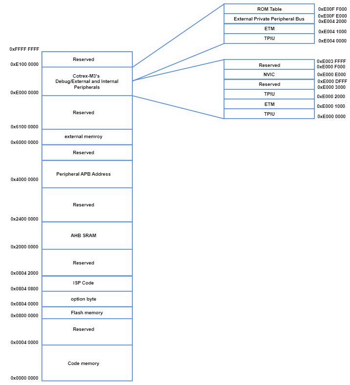
From the above figure, the Flash and SRAM addresses of the AutoChip AC7811 range from 0x000 0000 to 0x2000 0000 and 0x2000 0000 to 0x4000 0000 respectively, and the internal peripheral bus addresses range from 0x4000 0000 to 0x6000 0000 (which is commonly referred to as _apb (advanced peripheral bus), External storage device address 0x6000 0000 ~ 0x6100 0000 (here is the address space mapped to external SPI FLASH), Cortex-M3 private Debug, external and internal bus interface address 0xe000 0000 ~ 0xe100 0000 (refer to Cortex-M3 Technical Reference Manual). This paper mainly talks about the application of Flash address 0x000 0000 ~ 0x2000 0000 and SRAM address 0x2000 0000 ~ 0x4000 0000.
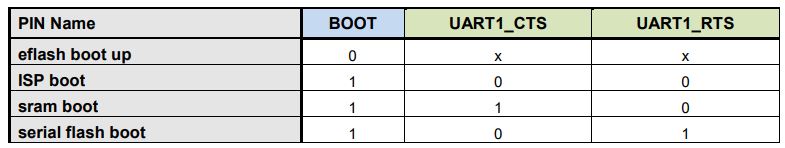
Next, by analyzing the four boot mode startup modes of AutoChip AC7811, we can help you understand the corresponding address mapping conversion. stay AC7811 technical reference manual page23 Boot configuration can set UART1_CTS and UART1_RTS pin enables different startup modes.
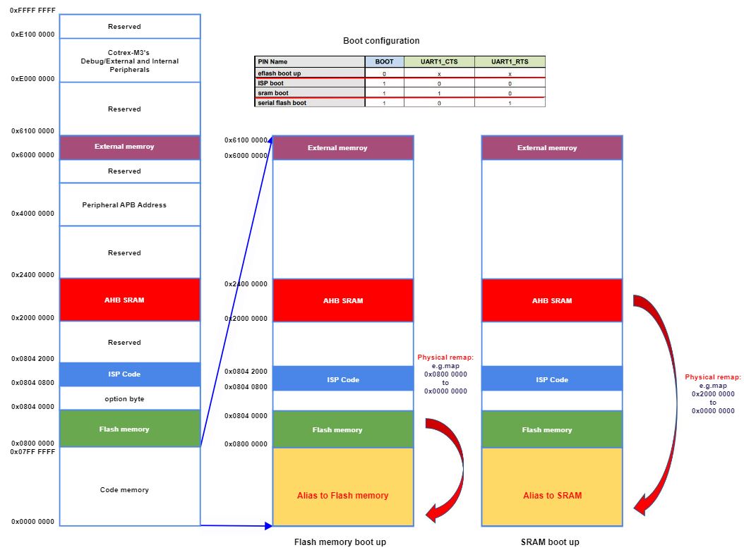
The mapping block diagram of Flash memory boot up} and SRAM boot up is as follows:
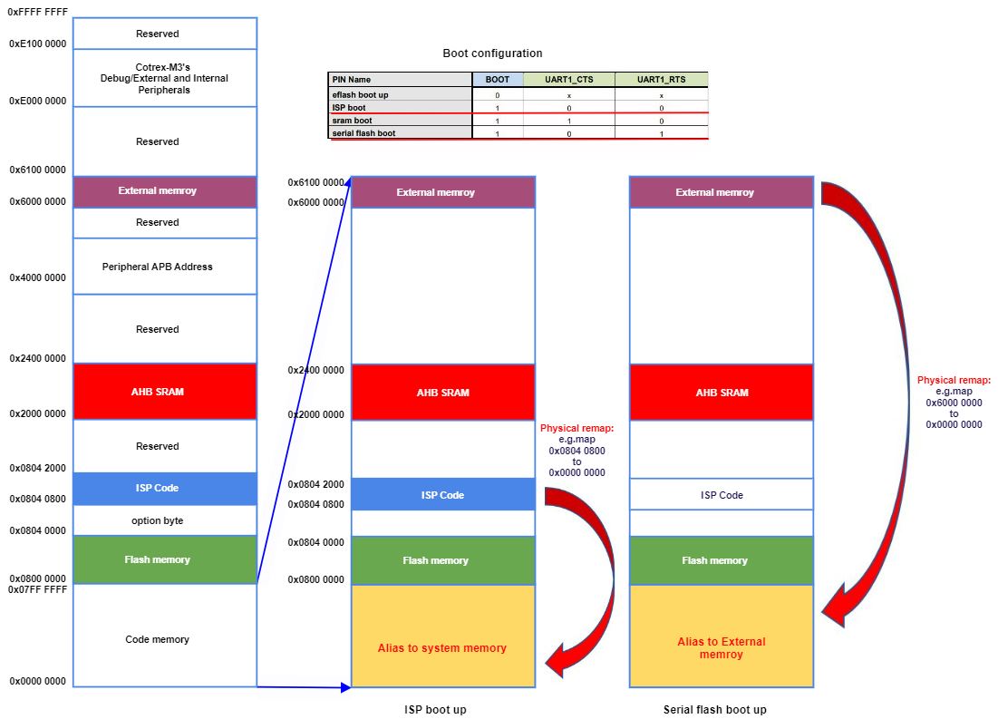
The mapping block diagram of ISP boot up # and Serial flash boot up is as follows:
Overall description of bare metal programs
We are all familiar with the application development supported by the operating system, such as the development of C language under Linux. We don't need to care about the details of program startup. At the same time, we can generally use various convenient lib libraries, such as basic IO operation (printf scan), dynamic memory allocation operation (malloc), file operation (fopen fwrite fread), etc. With the support of the operating system, the compilation, linking and startup of the program are supported by the operating system. The commonly used programming library functions use the standard C library.
If you want to implement these functions without OS support, what should you do? This is called Bare Metal program development. It is a common situation in embedded development. This paper mainly explains the naked program development based on Cortex-M3. The Bare Metal program realizes the functions of basic IO, dynamic memory allocation, basic function library and so on.
How to implement startup
Compared with the case with OS support, when analyzing a project with OS, it is generally analyzed from three aspects: first, the organization form of source code; First, look at the compile & & link Process (i.e. Makefile); The third is to look at the situation during Run (generally look at the processes and threads after running, as well as the relationship between them). After analyzing these three aspects, the whole project from static to dynamic and the transformation between dynamic and static are included, so we can master the whole project.
In the absence of OS, 1 and 2 are the same, except that the basic environment for program operation is different, and bare metal program operation needs to consider more details. Bare metal programs need to consider the following basic issues:
-
What is the executable structure generated by compilation? Where is the entrance of the whole executable program?
-
Where do I need to download the executable? What preparations need to be made before the program runs?
-
What kind of environment does C language need to run?
According to the above method, we analyze our Project from 3 aspects.
Source code:
Top level directory structure:
# tree -l
.
├── App
├── Device
│   ├── Include
│   │   ├── CMSIS
│   └── Source
│       ├── ARM
├── Drivers
│   ├── inc
│   └── src
└── makefile
The App directory is the main logic code of the Application layer, where main C is in the App directory and is the main code of the business logic layer. The device -- > include -- > CMSIS directory is the interface description file of the arm cmsis framework layer. The device -- > source -- > arm directory is the startup code startup_ac78xx.s and ac7811_flash.ld script. ac7811_flash.ld script mainly tells LD (linker) how to link various Objects files into executable programs Drivers directory is the SDK package of ac7811 provided by AutoChip.
More detailed project directory structure:
# tree -l
.
├── App
│   └── main.c
├── Device
│   ├── Include
│   │   ├── CMSIS
│   │   │   ├── arm_common_tables.h
│   │   │   ├── arm_const_structs.h
│   │   │   ├── arm_math.h
│   │   │   ├── cmsis_armcc.h
│   │   │   ├── cmsis_armclang.h
│   │   │   ├── cmsis_compiler.h
│   │   │   ├── cmsis_gcc.h
│   │   │   ├── cmsis_iccarm.h
│   │   │   ├── cmsis_version.h
│   │   │   ├── core_cm3.h
│   │   │   ├── mpu_armv7.h
│   │   ├── ac78xx.h
│   │   ├── ac78xx_ckgen.h
│   │   ├── ac78xx_debugout.h
│   │   ├── ac78xx_spm.h
│   │   ├── debugzone.h
│   │   └── system_ac78xx.h
│   └── Source
│       ├── ARM
│       │   ├── ac7811_flash.ld
│       │   └── startup_ac78xx.s
│       ├── ac78xx_ckgen.c
│       ├── ac78xx_ckgen_regs.h
│       ├── ac78xx_debugout.c
│       ├── ac78xx_spm.c
│       ├── ac78xx_spm_regs.h
│       ├── syscalls.c
│       └── system_ac78xx.c
├── Drivers
│   ├── inc
│   │   ├── ac78xx_can.h
│   │   ├── ac78xx_can_reg.
│   │   ├── ac78xx_dma.h
│   │   ├── ac78xx_dma_reg.h
│   │   ├── ac78xx_eflash.h
│   │   ├── ac78xx_eflash_reg.h
│   │   ├── ac78xx_uart.h
│   │   ├── ac78xx_uart_reg.h
│   │   ├── ......
│   └── src
│       ├── ac78xx_can.c
│       ├── ac78xx_dma.c
│       ├── ac78xx_eflash.c
│       ├── ac78xx_uart.c
│       ├── ......
└── makefile
Compiling and linking
Of course, it's direct make. However, we still need to know the corresponding compilation rules. I have to say that the makefile of AC7811 is very standard. We can use it as a good makefile template.
Detailed description of makefile:
#---------------------------------Compile parameters------------------------------------
#The command parameter log during compilation is not displayed on the screen
ifneq ($(V),1)
Q		:= @
NULL	:= 2>/dev/null
endif

TARGET := DEMO#The name of the compiled file can be modified according to the naming needs
OPT    := -O0#No optimization, which is the default compilation option.
CSTD   := -std=c11#Use C11 standard library
CXXSTD := -std=c++11#Using C++11 standard library

#--------------The header files that need to be compiled for the project can be added as needed--------------------
INC_FLAGS += -I ./Device/Include     \
		     -I ./Device/Include/CMSIS \
			 -I ./Drivers/inc
#------Link file, which specifies the chip flash and ram size, which needs to be modified according to the actual size
LDSCRIPT := ./Device/Source/ARM/ac7811_flash.ld

ARCH_FLAGS += -mthumb#thumb instruction
ARCH_FLAGS += -mcpu=cortex-m3#cortex-m3 cpu architecture

#Compile alarm settings
CWARN_FLAGS += -Wall -Wshadow
CWARN_FLAGS += -fno-common -ffunction-sections -fdata-sections
CWARN_FLAGS += -Wimplicit-function-declaration
CWARN_FLAGS += -Wstrict-prototypes

#--To print the serial port log through printf, set - specs = nosys Specs, and in syscalls Implemented in C_ write_r function to map printf to the serial port.
LDLIBS		+= -Wl,--start-group -lc -lgcc  -Wl,--end-group -lm -specs=nosys.specs

#-----------------------------Search the source code in the project directory---------------------------

AS_SRC := ./Device/Source/ARM/startup_ac78xx.s
AS_OBJ := $(AS_SRC:%.s=%.o)
#-------The source code shall be deleted according to the actual situation-------------
C_SRC := ./Device/Source/ac78xx_ckgen.c    \
		 ./Device/Source/ac78xx_spm.c      \
		 ./Device/Source/system_ac78xx.c   \
		 ./Device/Source/ac78xx_debugout.c \
		 ./Device/Source/syscalls.c \
		 ./Drivers/src/ac78xx_dma.c	\
		 ./Drivers/src/ac78xx_gpio.c	\
		 ./Drivers/src/ac78xx_timer.c	\
		 ./Drivers/src/ac78xx_uart.c	\
		 ./Drivers/src/ac78xx_wdg.c	\
		 ./App/main.c
C_OBJ := $(C_SRC:%.c=%.o)

#---------------------------------Parameter integration------------------------------------
# C flags
CFLAGS := $(OPT) $ $(CSTD) $(INC_FLAGS) $(FP_FLAGS)
CFLAGS += $(DEFINES) $(ARCH_FLAGS) $(CWARN_FLAGS) -g #-g add debugging options, and GDB can be used for debugging

# Linker flags linker compilation options
LDFLAGS		:= --static#Static compilation
LDFLAGS		+= -Wl,-Map=$(TARGET).map -Wl,--gc-sections
LDFLAGS		+= -T$(LDSCRIPT) $(ARCH_FLAGS) $(LDLIBS)

# OBJ
OBJ = $(AS_OBJ) $(C_OBJ)

#--------------------------------Compiler call instruction--------------------------------
PREFIX	:= arm-none-eabi

CC		:= $(PREFIX)-gcc
CXX		:= $(PREFIX)-g++
LD		:= $(PREFIX)-gcc
AR		:= $(PREFIX)-ar
AS		:= $(PREFIX)-as
OBJCOPY	:= $(PREFIX)-objcopy
OBJDUMP	:= $(PREFIX)-objdump
GDB		:= $(PREFIX)-gdb

.SUFFIXES: .elf .bin .hex .list .map .images
.SECONDEXPANSION:
.SECONDARY:

all: elf bin hex

elf: $(TARGET).elf
bin: $(TARGET).bin
hex: $(TARGET).hex
list: $(TARGET).list
images: $(TARGET).images

%.images: %.bin %.hex %.list %.map
	@printf "*** $* images generated ***\n"
#objdump generates binary files
%.bin: %.elf
	@printf "  OBJCOPY $(*).bin\n"
	$(Q)$(OBJCOPY) -Obinary $(*).elf $(*).bin
#objdump generates hex files
%.hex: %.elf
	@printf "  OBJCOPY $(*).hex\n"
	$(Q)$(OBJCOPY) -Oihex $(*).elf $(*).hex

%.list: %.elf
	@printf "  OBJDUMP $(*).list\n"
	$(Q)$(OBJDUMP) -S $(*).elf > $(*).list
#Link map to generate elf rules
%.elf %.map: $(OBJ) $(LDSCRIPT)
	@printf "  LD      $(TARGET).elf\n"
	$(Q)$(LD) $(OBJ) $(LDFLAGS) -o $(TARGET).elf
#Assembly file Compilation Rules
$(AS_OBJ): %.o:%.s
	@printf "  AS      $(*).s\n"
	$(Q)$(CC) $(ARCH_FLAGS) $(FP_FLAGS) -g -Wa,--no-warn -x assembler-with-cpp -o $(*).o -c $(*).s
#C file Compilation Rules
$(C_OBJ): %.o:%.c
	@printf "  CC      $(*).c\n"
	$(Q)$(CC) $(CFLAGS) -o $(*).o -c $(*).c

clean:
	@#printf "  CLEAN\n"
	$(Q)$(RM) $(shell find -name '*.o' -o -name '*.d' -o -name '*.elf' -o -name '*.bin')
	$(Q)$(RM) $(shell find -name '*.hex' -o -name '*.srec' -o -name '*.list' -o -name '*.map')
	$(Q)$(RM) $(shell find -name 'generated.*' -o -name '*.srec' -o -name '*.list' -o -name '*.map')

.PHONY: images clean elf bin hex list flash debug
Makefile Tips
(1)Common variable names(Conventional):
CC:express c Compiler Version
CFLAGS:Represents a compile time parameter
CPPFLAGS:Represents preprocessing parameters
CXX:express C++Compiler Version
CXXFLAGS:express c++Compile time parameters
LDFLAGS:Represents library parameters and library options
INCLUDE:Represents the header file directory
TARGET:Indicates the target name
RM:delete the selected entry
#: annotation symbols
(2)Some special characters
$(variable):Value the variable
@:Only the command results are displayed, ignoring the command itself
-:If the current command fails, ignore the error and continue
%:Wildcard, which is implemented by traversal
(3)Special variable
 For current target:
$@: Representative target
$<: Represents the first of the dependencies
$^: Represents all dependencies
Image structure and operation
When there is an operating system, we don't need to care about the specific structure of the executable image. The process from static file to dynamic operation of an executable program file is called loader & & run. This process is completed by OS, and application level development does not need to care about these details. For details on how the OS handles link & & loader, please refer to the following books:
What we are dealing with here is the startup details of the bare program. First, we need to know the structure of the binary executable image obtained through the compiler and linker. That is to say, the * What does the bin file look like? One picture wins ten thousand words. The last picture comes first.
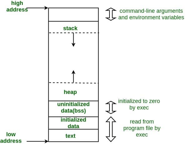
Everyone knows Feng The basic idea of Neumann architecture computer is to "write the steps of doing things and the resources needed in advance, and then let the computer read the operation steps and resources according to needs to realize part of computing automation". The design idea of computer is exquisite, and the realization of real computing automation is also the long cherished wish of many scientists and engineers. The steps of doing things mentioned above are called instructions in the computer field, and the required resources are called data in the computer field. From the perspective of computer architecture, executable image is actually divided into two parts: instruction and data. The instruction part is relatively single. Finally, the instruction parts in each source file are gathered together to form the so-called text segment. Functionally, the code segment only needs to be read by the CPU and does not need to be modified, because it can be placed in the RO memory. From the functional point of view, the data part must support reading and writing, that is, the data segment must be located in RW memory during execution. In terms of functional details, the data segment is divided into BSS segment, data segment, Stack segment and heap segment. From the perspective of computer architecture, from the perspective of data life cycle, the life cycle of some data is consistent with that of programs (global variables), The life cycle of some data is allocated and released immediately according to the usage (local variables and malloc dynamically allocated variables). BSS segment and data segment belong to the data of the whole life cycle. In the source program, they are mainly the global variables defined in the file field and the full life cycle variables defined with the static keyword. Data is the variables initialized to fixed values when variables are defined in the program, and BSS segment is the variables that are not initialized when variables are defined in the program Variables that are automatically initialized to 0 before the image is actually executed. One more thing about the BSS segment is that the BSS segment does not occupy specific space in the image file, because there is no specific information. You only need to provide the starting address and size information of the BSS segment in the image file. Before the actual execution of the image file, reserve the data areas required by the BSS segment in the actual RAM and initialize these areas to 0. Short life cycle data include heap and Stack, which are characterized by application when used and release when used up, which is more flexible. Heap is a large space reserved, which can be applied for and released at any time according to needs. The common malloc free function operation space is heap space. This part of space is an independent space in the image. See the program image above.
We can see that the address field of RO(RO-CODE/CODE+RO_DATA/CONST+RW_DATA) stored in Flash Memory is 0x08000000 – 0x0801FFFF, a total of 128K.
The address field of RW storage (RW_CODE+RW_DATA+ZI_DATA)SRAM is 0x20000000 – 0x20007FFF, 32K in total.
Let's take a look at the compiled MAP file and it's clear at a glance:
    Total RO  Size (Code + RO Data)                12008 (  11.73kB)
    Total RW  Size (RW Data + ZI Data)              2664 (   2.60kB)
    Total ROM Size (Code + RO Data + RW Data)      12068 (  11.79kB)
You can understand that RO includes code segments and read-only data segments, and RW includes data segments and BSS segments.
The startup configuration of MCU starts from 0x08000000 address. In order to save RAM space, we do not move the code segments of the image at startup, but directly read the Flash Memory. The data segments need to be readable and writable, so we need to move all the data segments to ram. Let's look at our startup code startup_ac78xx.s. We have CopyDataInit and FillZerobss.
.global  g_pfnVectors
.global  Default_Handler

/* start address for the initialization values of the .data section.
defined in linker script */
.word  _sidata
/* start address for the .data section. defined in linker script */
.word  _sdata
/* end address for the .data section. defined in linker script */
.word  _edata
/* start address for the .bss section. defined in linker script */
.word  _sbss
/* end address for the .bss section. defined in linker script */
.word  _ebss
/* stack used for SystemInit_ExtMemCtl; always internal RAM used */

/**
 * @brief  This is the code that gets called when the processor first
 *          starts execution following a reset event. Only the absolutely
 *          necessary set is performed, after which the application
 *          supplied main() routine is called.
 * @param  None
 * @retval : None
*/

    .section  .text.Reset_Handler
  .weak  Reset_Handler
  .type  Reset_Handler, %function
Reset_Handler:

/* Copy the data segment initializers from flash to SRAM */
  movs  r1, #0
  b  LoopCopyDataInit

CopyDataInit:
  ldr  r3, =_sidata
  ldr  r3, [r3, r1]
  str  r3, [r0, r1]
  adds  r1, r1, #4

LoopCopyDataInit:
  ldr  r0, =_sdata
  ldr  r3, =_edata
  adds  r2, r0, r1
  cmp  r2, r3
  bcc  CopyDataInit
  ldr  r2, =_sbss
  b  LoopFillZerobss
/* Zero fill the bss segment. */
FillZerobss:
  movs  r3, #0
  str  r3, [r2], #4

LoopFillZerobss:
  ldr  r3, = _ebss
  cmp  r2, r3
  bcc  FillZerobss

/* Call the clock system intitialization function.*/
  bl  SystemInit
/* Call static constructors */
/*    bl __libc_init_array    */
/* Call the application's entry point.'*/
  bl  main
  bx  lr
.size  Reset_Handler, .-Reset_Handler
The general situation is shown in the figure below:
Link Script, which controls how to generate the final image file. Before analyzing the specific Link Script, let's talk about the most important concept in Link Script, address & & offset. As mentioned earlier, when it comes to the image file format, there are all kinds of continuous contents (segments) and addresses. Therefore, the address is a very important resource for the image. Link Script is nothing more than telling the linker where to put something. Those sections need to be transported, and of course, the transportation also needs an address.
Let's take a look at the Link Script used in our project: one is related to Memory Map and the other is related to segment allocation. First look at the Memory Map,
/* Specify the memory areas */
MEMORY
{
  FLASH (rx)      : ORIGIN = 0x08000000, LENGTH = 128K
  RAM (xrw)       : ORIGIN = 0x20000000, LENGTH = 32K
  MEMORY_B1 (rx)  : ORIGIN = 0x60000000, LENGTH = 0K
}
# (rx) indicates that the attributes of this area are read-only and executable
# (xrw) indicates that the attributes of this area are read-write and executable attributes
Therefore, it can also be understood that RO represents FLASH area and RW represents RAM area.
The link script defines the various segments mentioned above isr_vector,. text, . data, . bss, heap and stack.
.isr_vector
/* Define output sections */
SECTIONS
{
  /* The startup code goes first into FLASH */
  /* isr_vector The startup code interrupt service vector table area starts from the so-called zero address 0x0800 0000*/
  .isr_vector :
  {
    . = ALIGN(4);
    KEEP(*(.isr_vector)) /* Startup code */
    . = ALIGN(4);
  } >FLASH
......
......
}
. text segment
/* Define output sections */
SECTIONS
{
......
......
  /* The program code and other data goes into FLASH */
  .text :
  {
    . = ALIGN(4);
    *(.text)           /* .text sections (code) */
    *(.text*)          /* .text* sections (code) */
    *(.rodata)         /* .rodata sections (constants, strings, etc.) */
    *(.rodata*)        /* .rodata* sections (constants, strings, etc.) */
    *(.glue_7)         /* glue arm to thumb code */
    *(.glue_7t)        /* glue thumb to arm code */
	*(.eh_frame)

    KEEP (*(.init))
    KEEP (*(.fini))

    . = ALIGN(4);
    _etext = .;        /* define a global symbols at end of code */
  } >FLASH
......
......
}
. data segments and bss segment
. The data section stores the initialized global and local static variables The rodata section stores read-only data. Generally, it is a read-only variable in the program (such as const modified variable and string variable) The bss segment stores uninitialized global and local variables.
It defines the layout of each segment in the image file and defines which segments need to be moved from FLASH to RAM before running. Let's take out a data segment to explain.
/* Define output sections */
SECTIONS
{
......
......
/* used by the startup to initialize data */
  _sidata = .;

  /* Initialized data sections goes into RAM, load LMA copy after code */
  .data : AT ( _sidata )
  {
    . = ALIGN(4);
    _sdata = .;        /* create a global symbol at data start */
    *(.data)           /* .data sections */
    *(.data*)          /* .data* sections */

    . = ALIGN(4);
    _edata = .;        /* define a global symbol at data end */
  } >RAM

  /* Uninitialized data section */
  . = ALIGN(4);
  .bss :
  {
    /* This is used by the startup in order to initialize the .bss secion */
    _sbss = .;         /* define a global symbol at bss start */
    __bss_start__ = _sbss;
    *(.bss)
    *(.bss*)
    *(COMMON)

    . = ALIGN(4);
    _ebss = .;         /* define a global symbol at bss end */
    __bss_end__ = _ebss;
  } >RAM

  PROVIDE ( end = _ebss );
  PROVIDE ( _end = _ebss );
......
......
}
The above script defines a segment called data, which contains the data segments in all Objects files. The global variables and static variables defined in different files are all aggregated into this segment. Some labels are also defined. These labels are actually the addresses (Address/Offset) of each data or segment in the image file. They are mainly used to provide the program with these address information and let the program process these resources in the image file. Like this data segment, you need to copy the data segment from FLASH to RAM during startup initialization. Since you want to copy, the program needs to know the source address, destination address and the length to copy. The start address is the Offset address of the data segment in the whole image, which is called_ sdata, the end address is_ edata, when you know the start address and end address, you know all the information of the information source (start address, end address and length). What's the destination address? Don't worry. The destination address is set by using the {AT} instruction, which means to tell the linker that this content needs to be transported. The download address is different from the running address.
  .fini_array :
  {
......
......
  } >FLASH
/* used by the startup to initialize data */
  _sidata = .;

  /* Initialized data sections goes into RAM, load LMA copy after code */
  .data : AT ( _sidata )
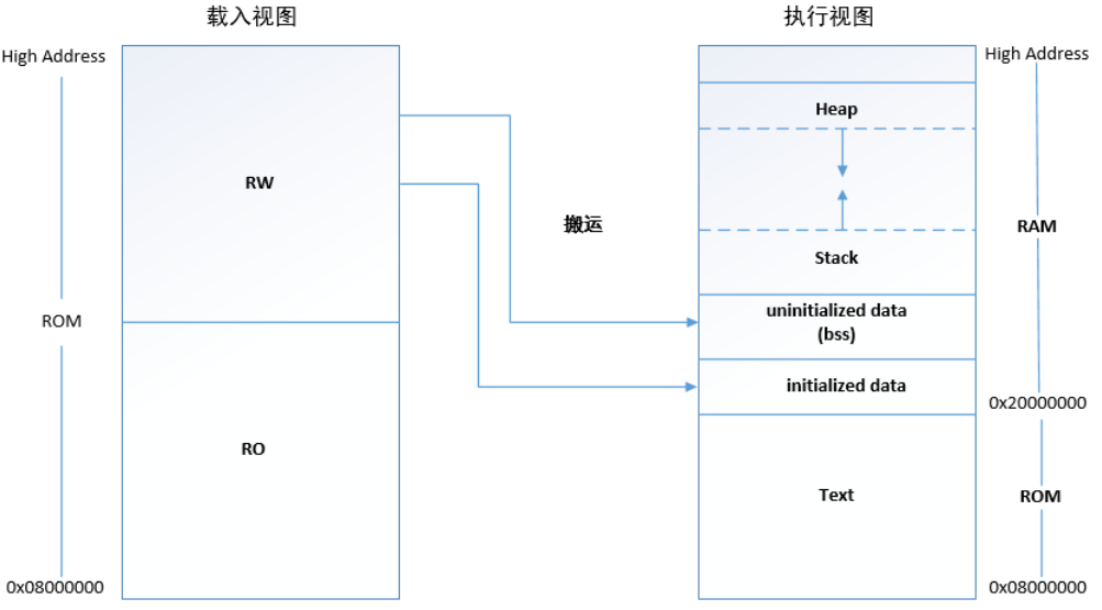
The above instruction means that the actual link address of this segment is the beginning of 0x20000000 defined in RAM Memory Region, which is put back according to the content. However, the actual position in the image now starts AT the beginning of 0x08000000 defined in FLASH Memory Region, and is placed in order according to the content. In the memory field of FLASH, the startup code and other code segments may have been placed in front. After using this description, the effect is that the contents are continuously stored in the image file (0x08000000 as the base address), but the actual link address of the data segment is 0x20000000 as the base address. For example, you define a global variable int A = 88;, Its actual running address is 0x20000010, but AT the beginning, the whole image is in FLASH, and its actual location in the image may be 0x08000100. In the code AT the beginning of the program (before using this global variable), the data segment needs to be moved from FLASH to ram as a whole. If the * * AT * * instruction is not used, the image file will be generated directly according to the link address, which means that the image file will be large, because there is a Gap between the code segment 0x0800000 and the data segment 0x20000000, which needs to be filled with a large number of zeros. I think it's a big image.
We can find it in the corresponding map file data
.fini_array     0x08004aa8        0x4
                0x08004aa8                PROVIDE (__fini_array_start = .)
 *(.fini_array*)
 .fini_array    0x08004aa8        0x4 d:/toolchain/msys64/mingw32/bin/../lib/gcc/arm-none-eabi/10.1.0/thumb/v7-m/nofp/crtbegin.o
 *(SORT_BY_NAME(.fini_array.*))
                0x08004aac                PROVIDE (__fini_array_end = .)
                0x08004aac                _sidata = .

.data           0x20000000      0x848 load address 0x08004aac
                0x20000000                . = ALIGN (0x4)
                0x20000000                _sdata = .
 *(.data)
Means that the data segment data is stored in FLASH from_ sidata starts from the source address 0x08004aac, the length of the data segment is 0x848, and the copy to the destination address is 0x20000000.
heap and stack
  .heap :
  {
    . = ALIGN(8);
    __end__ = .;
    PROVIDE(end = .);
    PROVIDE(_end = .);
    PROVIDE(__end = .);
    __HeapBase = .;
    . += _minimum_heap_size;
    __HeapEnd = .;
    __heap_end = .;
  } >RAM

  .stack :
  {
    . = ALIGN(8);
    . += _minimum_stack_size;
  } >RAM

  /* Define the stack.  The stack is full descending so begins just above last byte
   of RAM.  Note that EABI requires the stack to be 8-byte aligned for a call. */
  _estack = ORIGIN(RAM) + LENGTH(RAM) - _estack_reserve;
  _sstack = _estack - _minimum_heap_size;
  PROVIDE(__stack = _estack);
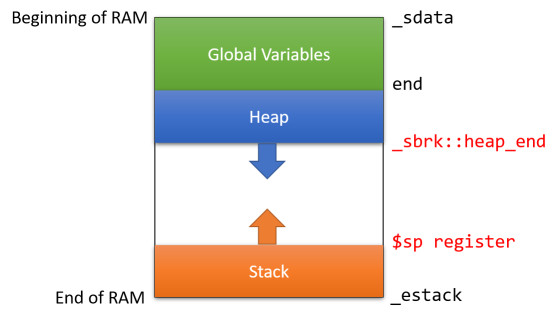
The following two figures vividly describe the distribution of DATA segment, heap and stack in RAM space:
Give a simple example of function call to help you understand the principle of heap and stack.
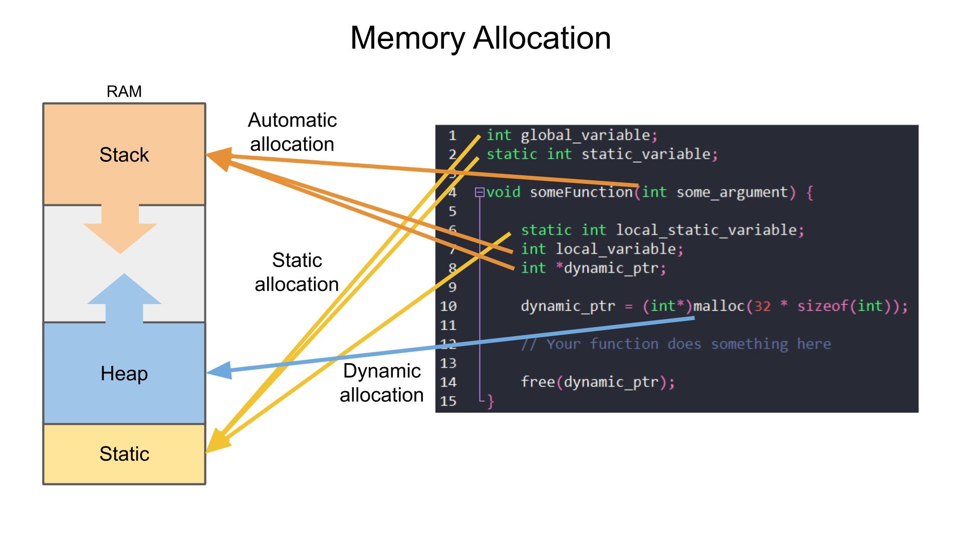
In the C file in the figure, the global variable is global_variable, Static variable_ Variable and the Static variable local inside the function_ Static_ Variables belong to global variables, and there is a Static area. Temporary variables inside function arguments are pushed in stack area. The memory obtained from malloc in the function Get in the heap area.
So what's the difference between Stack and Heap? As shown below:
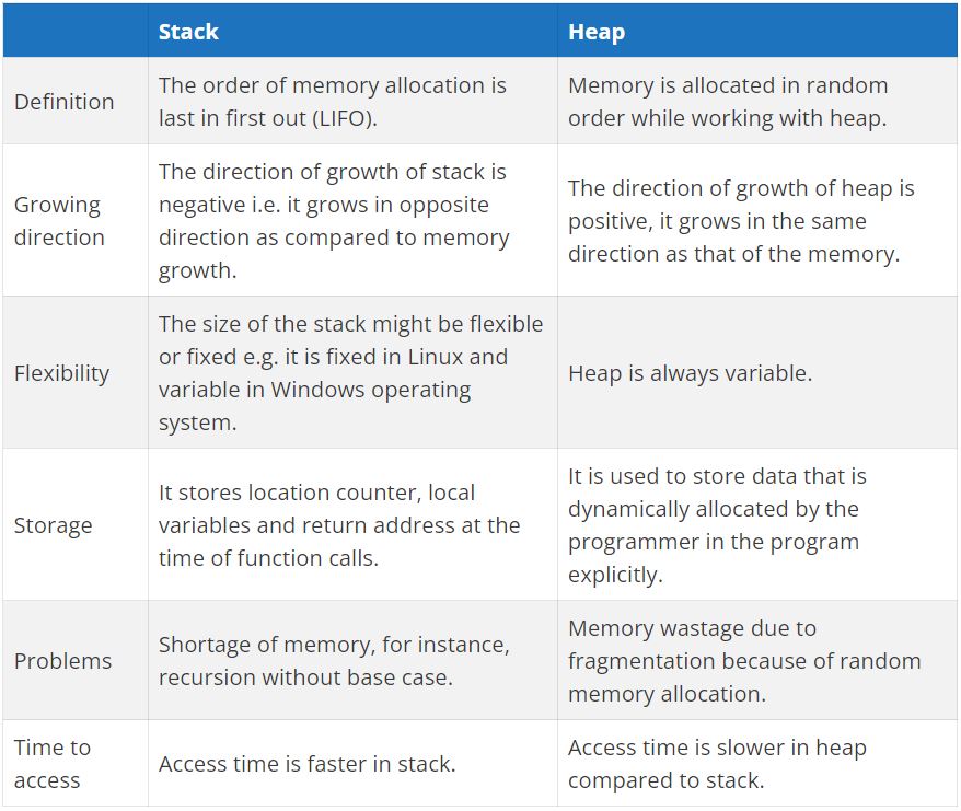
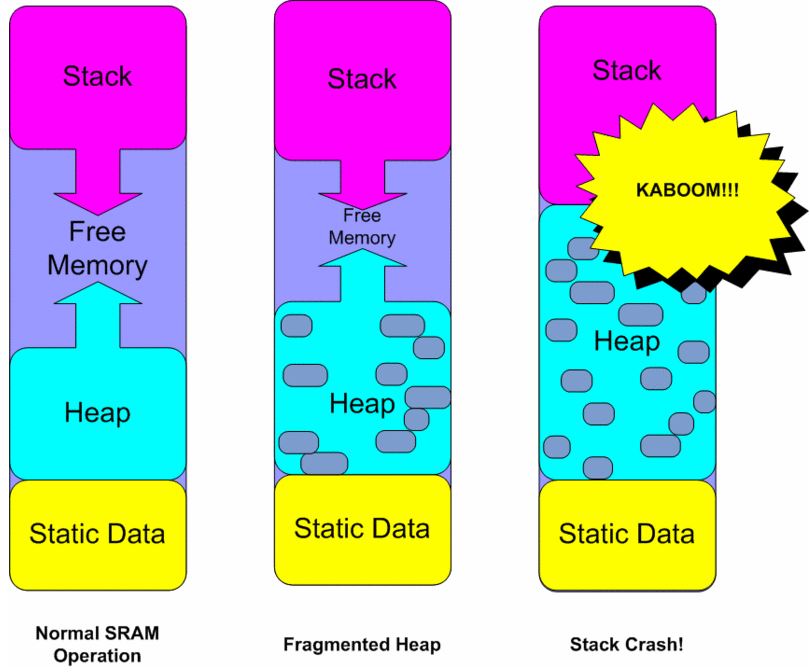
The following figure can help you understand the problems prone to Heap in the application. Because memory allocation is applied randomly, it will lead to Fragmented Heap. If Stack and Heap do not have boundary protection, it will lead to Stack Crash.
summary
That's all for now. However, it should be enough to help you decrypt the code operation principle of CotrexM3 ARM. In this way, how and where your code runs completely dominate your hands. There may be some inaccuracies, irrationalities or errors in this article. I hope you can correct them. I will try my best to improve it. As for some places that are not detailed enough, I will find time to fill them in later.
reference material:
Difference between stack and heap
The Difference Between Stack and Heap Based Memory
Stack and Heap Layout of Embedded Projects
STM32 memory allocation parsing and variable storage location
what does system memory work actually in STM32F103 on ARM memory map?
Introduction to RTOS - Solution to Part 4 (Memory Management)