Introduction to infrared
The visible light that can be seen by human eyes is arranged according to the wavelength from long to short, which is red (660nm), orange (610nm), yellow (585nm), green (555nm), green (500nm), blue (460nm) and violet (405nm). Light shorter than the wavelength of violet light is called ultraviolet, and light longer than the wavelength of red light is called infrared. As follows:
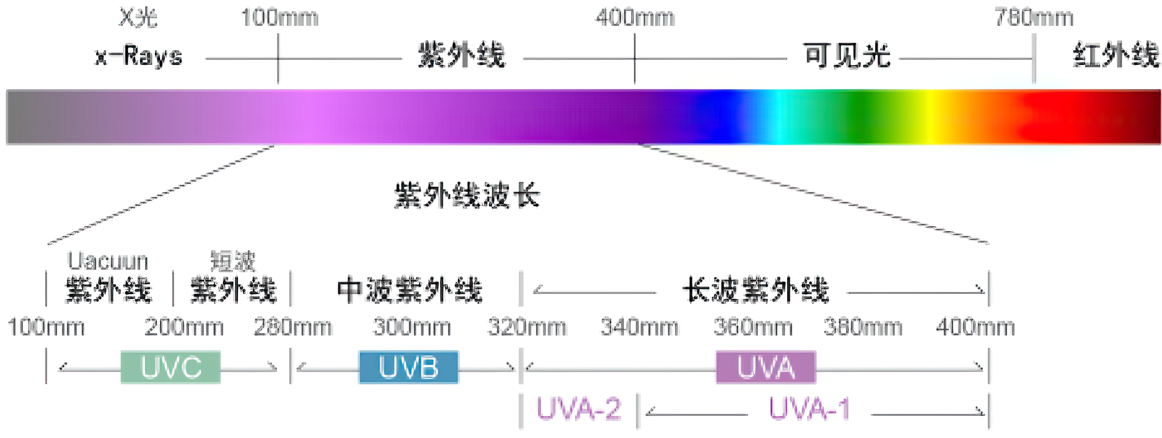
Infrared remote control uses a wavelength of 0.76 ~ 1.5 μ m to transmit the control signal.
Principle of infrared remote control
Infrared remote control is a wireless and non-contact control technology, which has the advantages of strong anti-interference ability, reliable information transmission, low power consumption, low cost and easy implementation.
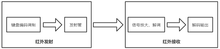
Infrared remote control communication system is usually composed of infrared transmitting device and infrared receiving device.
Infrared emitting device
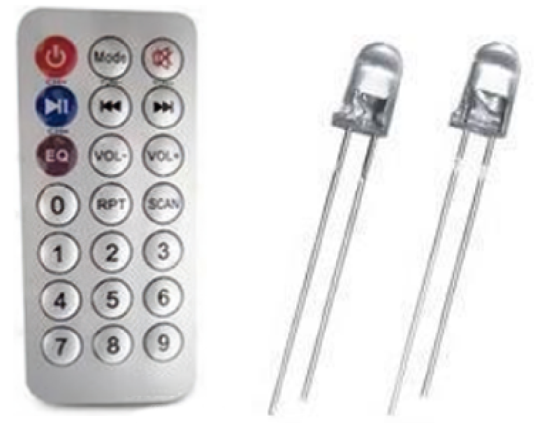
Infrared transmitting device, namely infrared remote controller, is composed of keyboard circuit, infrared coding circuit, power supply circuit and infrared transmitting circuit. The main component of the infrared emission circuit is the infrared light-emitting diode. Its internal material is different from the ordinary light-emitting diode. When a certain voltage is applied at both ends of the infrared light-emitting diode, it will emit infrared rather than visible light. The infrared wavelength emitted by the commonly used infrared LED is about 940nm. The infrared remote controller and infrared LED are shown in the figure below:
In order to improve anti-interference and reduce energy consumption, the infrared remote controller usually transmits binary coding by carrier. The common carrier frequency is 38KHz, which is determined by the 455kHz crystal oscillator used at the transmitting end (the crystal oscillator shall be divided by integer at the transmitting end, and the frequency division coefficient is generally 12, so 455kHz ÷ 12 ≈ 37.9kHz ≈ 38KHz). The usual infrared remote controller modulates the remote control signal (binary pulse code) on a 38KHz carrier wave, which is buffered and amplified and then sent to the infrared light-emitting diode, which is converted into an infrared signal and transmitted.
There are many forms of binary pulse codes. The most commonly used are the PWM code (pulse width modulation) of NEC Protocol and the PPM code (pulse position modulation) of Philips RC-5 Protocol. To develop infrared receiving equipment, we need to know the coding mode and carrier frequency of infrared remote controller, so as to select the integrated infrared receiving head and formulate the decoding scheme. The infrared remote controller used in this paper uses NEC Protocol, with the following characteristics:
- 8-bit address and 8-bit instruction length
- Address and Command 2 transmission
- PWM pulse width modulation represents "0" and "1" with the duty cycle of transmitting infrared carrier, and the duty cycle is 1:3
- Carrier frequency: 38Khz
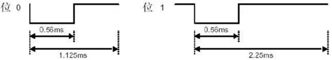
- Bit time is 1.125ms or 2.25ms
Bit definition of NEC Code: one pulse corresponds to 560us continuous carrier. The transmission of one logic 1 needs 2.25ms (560us pulse + 1680us low level), and the transmission of one logic 0 needs 1.125ms (560us pulse + 560us low level). The infrared receiving head is low when receiving the pulse and high when there is no pulse. Therefore, the signal received by the receiving head end is: logic 1 is 560us low + 1680us high (high level when there is no pulse), and logic 0 is 560us low + 560us high. Therefore, it is possible to determine whether the received data is 0 or 1 by calculating the high-level time. The sequence diagram of NEC code point definition is shown in the following figure:
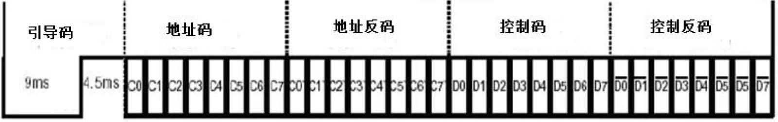
The data format of NEC remote control command is: guide code, address code, address inverse code, control code and control inverse code. The pilot code consists of a 9ms low level and a 4.5ms high level. The address code, address inverse code, control code and control inverse code are all in 8-bit data format. Send in the order of low order first and high order last. The inverse code is used to increase the reliability of transmission (which can be used for verification). The data format is as follows:
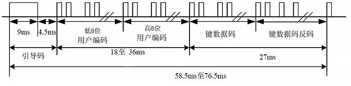
The complete NTC code is as follows:
The NEC code also specifies the continuous transmission code (composed of 9ms low level + 2.5m high level + 0.56ms low level + 97.94ms high level). If the button of the infrared remote controller is still not released after a frame of data is sent, the continuous transmission code is transmitted, and the length or times of pressing the button can be marked by counting the times of the continuous transmission code.
Infrared receiving equipment
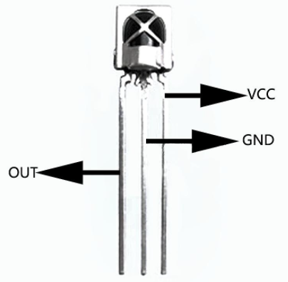
Infrared receiving equipment consists of infrared receiving circuit, infrared decoding, power supply and application circuit. The main function of the infrared remote control receiver is to convert the infrared optical signal sent by the remote control transmitter into an electrical signal, amplify, limit, detect and shape, form a remote control command pulse, and output it to the remote control microprocessor. Nowadays, the finished infrared receiver is usually used. There are roughly two kinds of packages for finished infrared receiving heads: one is shielded by iron sheet; One is plastic packaging. There are three pins, namely power supply positive (VDD), power supply negative (GND) and data output (VOUT). The physical appearance is shown in the figure below:
Because the infrared receiving head is high level when there is no pulse and low level when receiving the pulse, the interrupt can be triggered by the falling edge of the external interrupt, and the received data is 0 or 1 by calculating the high-level time within the interrupt.
hardware component
The hardware resources used are as follows:
- Dynamic nixie tube
- Infrared receiver and remote controller
Dynamic nixie tube circuit in the previous article Dynamic nixie tube experiment I've introduced them all, so I won't repeat them here. The infrared remote controller and the receiving head are integrated, and the internal structure does not need to care about it. The circuit of infrared receiving module is shown in the figure below:
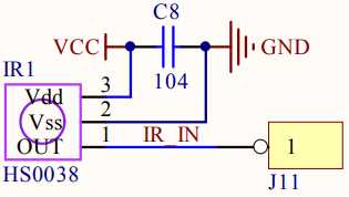
As can be seen from the above figure, the output pin of the infrared receiving head is connected to the J11 terminal. In order to ensure that the output pin of the infrared receiving head is at the high level by default, a 10k pull-up resistance needs to be connected externally, because the IO port of the single chip microcomputer has increased 10K pull-up resistance, so it can be omitted here. Here we use P3 2 pin (corresponding to the additional function of P3.2 port) is connected with the output pin of the infrared receiving head.
Software part
The function to be realized is to display the key value of infrared decoding remote controller on the nixie tube.
The procedure framework is as follows:
- Write nixie tube display function
- Write infrared decoding function
- Write main function
Infrared initialization function
Because the external interrupt 0 is used to decode the infrared remote control data, it is necessary to initialize and configure the external interrupt 0.
void ired_init(void)
{
    IT0=1; //Falling edge trigger
    EX0=1; //Enable interrupt 0
    EA=1; //Open total interrupt
    IRED=1; //Initialize port
}
Infrared decoding function
After initializing the external interrupt, the interrupt has been turned on. When the falling edge of P32 pin appears, the interrupt will be triggered. The high-level time will be calculated in the interrupt, and whether to enter the pilot code IRED and data 0 and 1 will be judged through the high-level time.
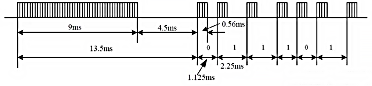
Enter the interrupt function, indicating that a falling edge is generated, and then judge whether the IRED (P3^2) is low level. If it is low level, first judge the pilot signal. As shown below, the pilot signal has a low level of 9ms:
According to the previous NEC protocol, the pilot signal has a low level of 9ms and a high level of 4.5ms. In order to calculate the time to judge whether there is 9ms, a variable time is used_ CNT is assigned a value of 1000, and then it is judged in the while loop, time_ Every time CNT decreases by about 10us, 1000 times is 10ms, and 10ms > 9ms, so it meets the judgment waiting time.
In simultaneous interpreting, this time (9ms) should be relaxed a little bit, because different sensor performance will be different, so the low level of 10ms is the boundary, if more than 10ms, then force to exit to prevent the system from running down.
time_cnt=1000;
while((!IRED)&&(time_cnt))//Wait for the low level of the pilot signal 9ms to end, and forcibly exit if it exceeds 10ms
{
    delay_10us(1);//Delay about 10us
    time_cnt--;
    if(time_cnt==0)return;	//1000*10us=10ms. If it is still low after 10ms, return to exit
}
Judge the low level of the pilot signal, and then judge the high level. The method is the same. When the pilot signal is judged, enter the data judgment of 4 bytes of address code, address inverse code, control code and control inverse code, that is, the judgment of data 0 and 1. The implementation method is the same as the previous judgment of the pilot signal. Here is the difficulty. Judge whether it is data 0 or 1, The key is to judge the low-level time: the transmission of a logic 1 needs 2.25ms (560us pulse + 1680us low-level), and the transmission of a logic 0 needs 1.125ms (560us pulse + 560us low-level). It is realized by judging 1680us or 560us. The codes of the key parts are as follows:
time_cnt=20;
while(IRED)//Wait for the high level after data 1 or 0 to end. If it exceeds 2ms, it will be forced to exit
{
    delay_10us(10);//About 0.1ms
    ired_high_time++;
    if(ired_high_time>=20)return; //2000us(0.1*20ms=2000us, if the maximum high-level time of logic 1 exceeds 1680us, it is forced to exit
}
gired_data[i]>>=1; //The low bit is read first, then the high bit
if(ired_high_time>=8) //Logic 1 is 560us low + 1680us high, and logic 0 is 560us low + 560us high. If the high-level time is greater than 0.8ms, the data is 1, otherwise it is 0
    gired_data[i]|=0x80;  //It is high level, so it is 1, i.e. 10 million. Because the low bit is transmitted and received first, it should be shifted to the right in the next reading, that is, gired_ data[i]>>=1;
ired_high_time=0;	//Reset and wait for the next byte data reading to determine whether it is 0 or 1
Note that the infrared remote control decoded data is transmitted from the low bit to the high bit. Finally, the read 4-byte data is stored in the global variable array gired_ In data, these four bytes can be directly used externally.
The specific code of infrared decoding function is as follows:
#include "ired.h"
u8 gired_data[4];//Store 4 byte receiving codes (address code + address inverse code + control code + control inverse code)

void ired_init(void)
{
 	IT0=1;	//External interrupt falling edge trigger
	EX0=1;	//Enable interrupt 0
	EA=1;	//Open total interrupt
	IRED=1;	//Initialize port
}

void ired() interrupt 0 //External interrupt 0 service function
{
 	u8 ired_high_time=0;
	u16 time_cnt=0;
	u8 i=0,j=0;

	if(IRED==0)
	{
	 	time_cnt=1000;
		while((!IRED)&&(time_cnt)) //Wait for the low level of the pilot signal 9ms to end, and forcibly exit if it exceeds 10ms
		{
		 	delay_10us(1);
			time_cnt--;		 //time_cntd decreases 1000 times, 10us once, 10ms in total
			if(time_cnt==0) return;	  //If it is still low level after 10ms, exit
		}
		if(IRED)   //The 9ms low level of the pilot signal has passed and entered the 4.5ms high level
		{
		 	time_cnt=500;
			while(IRED&&time_cnt) //Wait for 4.5ms high level of pilot signal to end. If it exceeds 5m or low level, it will be forced to exit
			{
			 	delay_10us(1);
				time_cnt--;
				if(time_cnt==0) return;	 //time_cntd decreases 500 times, 10us once, 5ms in total
			}
			for(i=0;i<4;i++) //Cycle for four times and read four bytes of data (representing address code, address inverse code, control code and control inverse code)
			{
			 	for(j=0;j<8;j++)  //Cycle eight times to read each bit of byte data
				{
					time_cnt=600;
					while((IRED==0)&&time_cnt)//Wait for 0.56ms before data 1 or 0 to end. If it exceeds 6ms, exit forcibly
					{
					 	delay_10us(1);
						time_cnt--;
						if(time_cnt==0)return;
					}
					time_cnt=20;
					while(IRED)//Wait for the high level after data 1 or 0 to end. If it exceeds 2ms, it will be forced to exit
					{
					 	delay_10us(10);//About 0.1ms
						ired_high_time++;
						if(ired_high_time>=20)return; //2000us(0.1*20ms=2000us, if the maximum high-level time of logic 1 exceeds 1680us, it is forced to exit
					}
					gired_data[i]>>=1; //First read the low order, then the high order
					if(ired_high_time>=8) //Logic 1 is 560us low + 1680us high, and logic 0 is 560us low + 560us high. If the high-level time is greater than 0.8ms, the data is 1, otherwise it is 0
						gired_data[i]|=0x80;  //It is high level, so it is 1, i.e. 10 million. Because the low bit is transmitted and received first, the next reading should be shifted to the right, that is, gired_ data[i]>>=1;
					ired_high_time=0;	//Reset and wait for the next byte data reading to determine whether it is 0 or 1
				}
			}
			if(gired_data[2]!=~gired_data[3]) //Check whether the control code and the inverse code are opposite to each other. If not, it indicates that the received data is wrong, and it will be given_ All data are cleared to 0 and returned
			{
			 	for(i=0;i<4;i++)
					gired_data[i]=0;
				return;
			}
		}
	}
}
Source code: link: https://pan.baidu.com/s/1NTxOkoPlCX8FFleA21i1ug?pwd=51yw Extraction code: 51yw
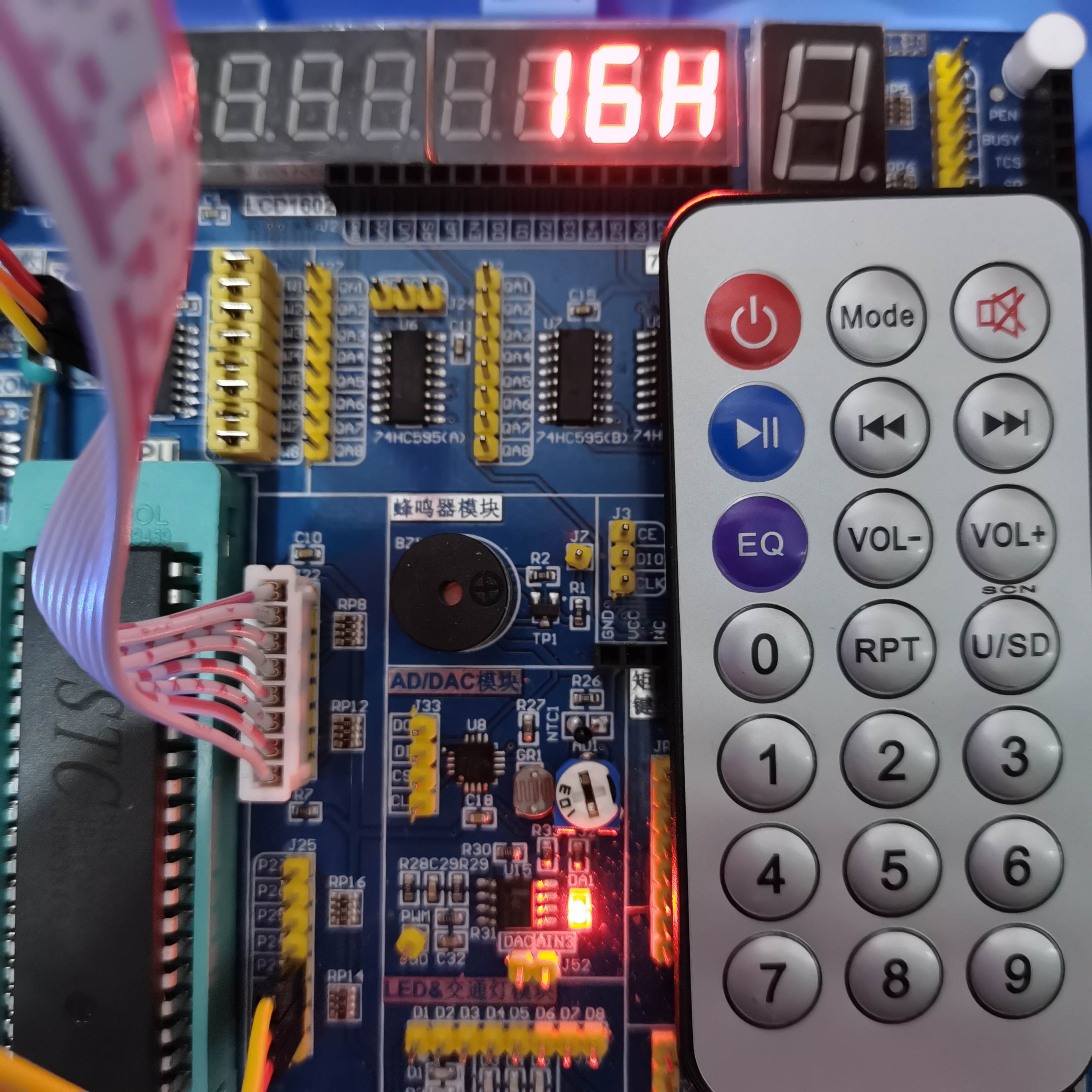
phenomenon
The key value of infrared decoding remote controller is displayed on the nixie tube.