Internet of things smart home DIY_TC32 series article directory
1. Environment construction and lighting
2. TC32 transparent transmission analysis
1, Foreword
Last time, it was said that the lighting of TC32 has been completed, and now combined with BLE_AT routine in the serial port transmission, make a small program light.
TC32 is mainly divided into two parts: wechat and wechat.
This article mainly records the revision and implementation of TC32. AT present, we can't fully understand the framework of the whole AT routine. We only know how to modify the code to realize the lighting function of applet.
The applet directly selects the routines provided in the Anxin tutorial. The next article will introduce how to make secondary modification.
2, Preconditions
UB18 + TC32 + serial port cable
3, References for this article
https://xuhong.blog.csdn.net/article/details/104657047
https://aithinker.blog.csdn.net/article/details/105443266
4, Body part
4.1 GPIO initialization
In the blink routine of the previous article, we can get that the GPIO initialization of TC32 is relatively simple.
GPIO has the following modes:
GPIO / MSPI / SWIRE / UART / I2C / SPI / I2S / AMIC / DMIC / SDM / USB / ADC / CMP / ATS / PWM / PWM_N
Setting the IO port to the output mode only requires the following steps:
1. Set the GPIO port to GPIO mode
2. Enable output and disable input
3. Finally, write the level into GPIO
gpio_write(GPIO_PC2, 0);
Setting the IO port to the input mode only requires the following steps:
1. Set the GPIO port to GPIO mode
2. Set to pull-up or pull-down mode, and set the corresponding resistance at the same time
PM_PIN_PULLUP_1M / PM_PIN_PULLDOWN_100K / PM_PIN_PULLUP_10K
3. Enable input and disable output
4. Finally, read the level status
gpio_read(GPIO_PD2)
void user_init()
{
	gpio_set_func(GPIO_PC2, AS_GPIO);

	/* Set PC2 to output mode */
	gpio_set_output_en(GPIO_PC2, 1);
	gpio_set_input_en(GPIO_PC2, 0);

	gpio_set_func(GPIO_PD2, AS_GPIO);
	gpio_setup_up_down_resistor(GPIO_PD2, PM_PIN_PULLUP_10K);
	gpio_set_output_en(GPIO_PD2, 0);
	gpio_set_input_en(GPIO_PD2, 1);
}
4.2 lighting logic analysis
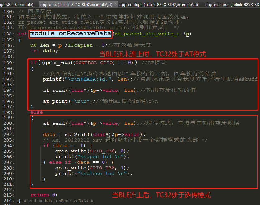
AT routines are mainly divided into two modes: AT mode when BLE is not connected and transparent mode after BLE is connected.
What we need to realize is that the applet lights up, that is, the applet is connected with TC32 through BLE, so we only need to initialize the GPIO of the led lamp at startup, use the applet to connect to TC32, and finally add the function of parsing the data from the applet in the code of transparent mode.
In the source code, the data of the applet is directly printed through the serial port. We only need to parse the received string, and turn on or off the led light when some man-made conditions are met.
4.3 TC32_SDK analysis
Now that you have found the place to modify, let's reverse the whole system flow
	int main (void)
		1. blc_pm_select_internal_32k_crystal();				//Determine whether the wake-up source is an internal 32k RC
		2. cpu_wakeup_init();									//Initialize MCU
		3. int deepRetWakeUp = pm_is_MCU_deepRetentionWakeup();	//Get MCU deep reservation wake-up
		4. rf_drv_init(RF_MODE_BLE_1M);							//Start RF mode
		5. gpio_init( !deepRetWakeUp );							//Initialize GPIO port (mode of uninitializing specific GPIO)
		6. clock_init(SYS_CLK_16/24/32M_Crystal);				//Clock initialization
		7. blc_app_loadCustomizedParameters(); 					//Load custom frequency offset upper limit value
		8. tinyFlash_Init(0x70000,0x4000);						//Initialize KV storage system
		9. If not deep sleep mode
				tinyFlash_Read(STORAGE_BAUD, baud_buf, &len);	//Read baud rate
				tinyFlash_Read(STORAGE_ATE, &ATE, &len);		//Read ATE
				tinyFlash_Read(STORAGE_MODE, &device_mode, &len);//Read ATE
		/**************************************/
		/* Here is the part that can be modified according to the actual situation */
		10. app_uart_init(baud_buf[0]);							//Initialize serial port
		11. my_gpio_init();										//Initialize GPIO
		12. blt_soft_timer_init();								// Initialization timer
		13. If not deep sleep mode
				Determine the device mode obtained from step 9 device_mode
					In case of host mode(1)
							ble_master_init_normal();
					In case of slave mode(0)
							ble_slave_init_normal();
								13.1 Initialize random number generator
										random_generator_init();
								13.2 BLE Protocol stack initialization
									13.2.1 Based on incoming flash Address acquisition public mac Address and random static address
										blc_initMacAddress(CFG_ADR_MAC, mac_public, mac_random_static);
										app_own_address_type
									13.2.2 Controller initialization
										blc_ll_initBasicMCU();                      //Mandatory
										blc_ll_initStandby_module(mac_public);		//Mandatory
										blc_ll_initAdvertising_module(mac_public); 	//adv module: BLE slave must be installed,
										blc_ll_initConnection_module();				//Connection module: BLE slave / master must be installed
										blc_ll_initSlaveRole_module();				//Slave module: BLE slave must,
									13.2.3 Host initialization
										gap initialization
											blc_gap_peripheral_init();
										gatt Initialization (this function is very important)!!!!!!!!!!)
											my_att_init();
										set up MTU 247
											blc_att_setRxMtuSize(247);
										l2cap initialization
											blc_l2cap_register_handler(blc_l2cap_packet_receive);
										SMP initialization
										(Smp Initialization may involve flash writing/Erase, so it must be done after the battery check)
										(When a sector stores too much information and is about to exceed the sector threshold, the sector must be erased and all useful information must be stored again)
											#if (BLE_REMOTE_SECURITY_ENABLE)
												blc_smp_peripheral_init();
											#else
												blc_smp_setSecurityLevel(No_Security);
											#endif
								13.3 User application layer initialization
									...

		14. irq_enable();										//Enable interrupt
		15. while (1)											//Main cycle
				15.1 If the watchdog is enabled, clear the watchdog
						wd_clear();
				15.2 sdk Main cycle? Only one interface is provided externally, and the implementation is not described
						blt_sdk_main_loop();
				15.3 If the current mode is the host mode, enter the host main cycle
						ble_master_mainloop();
				15.4 Serial port loop, i.e. user layer UART Cyclic sending and receiving data
						app_uart_loop();
							If at this time fifo There is data in the. Get and process the data
								data = my_fifo_get(&uart_rx_fifo)
							If Bluetooth is not connected or PC5 Response required at low level AT instructions
								device_in_connection_state == 0 || gpio_read(CONTROL_GPIO) == 0)
								Parse, process and respond fifo Medium AT command
									at_data_process((char*)(p->data), p->dma_len);
										a. filter \r \n
										b. analysis AT Mode corresponding to command (query)/set up/(help)
											mode = data_process_cmd_mode(pbuf);
										c. AT Command analysis and execution
											data_process_parse(pbuf + 3, mode, len-3)
												result = cmd_ptr->cmd_handle(ps, mode, dataLen);
							Otherwise, it is considered that Bluetooth is currently connected and enters transparent transmission mode
								Send data via BLE Send out
									bls_att_pushNotifyData(SPP_SERVER_TO_CLIENT_DP_H, p->data, p->dma_len);
							fifo Read write clock synchronization
								my_fifo_pop(&uart_rx_fifo);
									f->rptr++;
										rptr:Write pointer (write clock) to synchronize to the read clock field
				15.5 Software timer process
						blt_soft_timer_process(MAINLOOP_ENTRY);
My above_ att_ init(); Put it on the blog later and analyze it separately.. This part is the core content of the whole BLE, which has not been understood yet..