1. Related concepts of interruption
- The main interaction modes between the kernel and peripherals: polling and interrupt
The way of polling seems fair, but the actual work efficiency is very low and can not respond to emergencies in time
The interrupt system makes the kernel have the ability to deal with sudden conditions
- interrupt
The interruption of the program due to external reasons is called interruption:
- When executing the current program of the CPU, due to some urgent situation in the system, the CPU suspends the executing program and executes another special program to deal with the emergency
- After processing, the CPU automatically returns to the original suspended program to continue execution
- Two important concepts
Interrupt service function: the corresponding handler executed after the kernel responds to the interrupt
Interrupt vector: the entry address of the interrupt service program
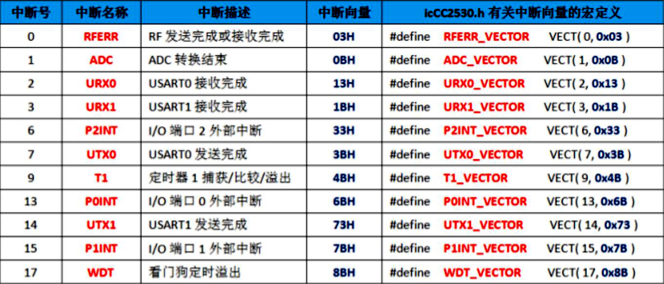
2.CC2530 interrupt system
- 18 interrupt sources are controlled by a series of special function registers
- You can compile, set priority and enable interrupt application response
- Common interrupt source
3. Writing method of CC2530 interrupt processing function
The interrupt service function is different from the general custom function and has a specific writing format
#Pragma vector = < interrupt vector >
__interrupt void<Function name>(void){  //Note: here are two underscores connected together
    /*Write a specific interrupt handler*/
}
- Before each interrupt service function, add a starting statement: #pragma vector = < interrupt vector >
< interrupt vector >: indicates which interrupt source the interrupt service function to be written next serves. It can be written in two ways:
- Entry address of interrupt vector: #pragma vector = 0x7B
- Macro definition of header file "ioCC2530.h": #pragma vector = P1INT_VECTOR
- __ Interrupt: indicates that the function is an interrupt service function
< function name >: it can be customized. The function body cannot have parameters or return values
4.CC2530 external interrupt
- P0, P1 and P2 ports use P0IF, P1IF and P2IF as interrupt flag bits respectively. When the pin on any port group generates an external interrupt, the interrupt flag of the corresponding port group will be set automatically
- The port status flag registers P0IFG, P1IGF and P2IFG respectively correspond to the interrupt trigger status of each pin in the three ports. When an external interrupt trigger occurs on a pin, the corresponding flag bit will be set automatically
Note: 1 The external interrupt flag must be cleared manually in the interrupt service function
2. The port status flag also needs to be cleared manually
5. Case: external interrupt input control LED light
requirement:
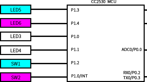
Set the SW1 key on the ZigBee small module as the external interrupt input pin. In the interrupt service function, control the switching of an LED6 light, that is, the original LED is on and off, and the original LED is off and on. At the same time, in the main program, run a running light program to turn LED3 and LED4 lights on and off in turn
Design idea:
- Port initialization and running light program, refer to General purpose IO port (GPIO) input and output control of CC2530
- Define an external interrupt initialization function, SW1 is P1_ Pin 2 is configured as an external interrupt input port, and its interrupt trigger mode is set to falling edge trigger
- Define an interrupt service function for an external interrupt according to the writing format of the interrupt service function. Note: clear the corresponding interrupt flag bit in the interrupt service function. The interrupt flag of the pin must be cleared first, and then the interrupt flag of the port group must be cleared
- Involving external interrupt initialization function Init_INTP()
External interrupt initialization function: it mainly completes the configuration of special function registers related to interrupts
- Configure the IENx register to enable the interrupt function of the port group
- Configure the PxIEN register to enable the specific external interrupt pin
- Configure PICTL register and set interrupt trigger mode
- Involving external interrupt service function Int1_Sevice()
- When writing interrupt service function, pay attention to the correct writing format and interrupt vector
- Note: in the function, clear the flags of the port group and pin manually, otherwise the CPU will enter the interrupt repeatedly. You must clear the pin flag bit PxIFG first, and then clear the port group flag bit PxIF
Complete source code
#include "ioCC2530.h"

#define LED6 P1_4
#define LED3 P1_0
#define LED4 P1_1

/*========================Delay function===========================*/

void Delay(unsigned int t){
  while(t--)
}

/*========================Port initialization function=====================*/

void Init_Port(){
  //Place P1_0,P1_1 and P1_4 set as general I/O port
  P1SEL &= ~0X13;
  //Place P1_0,P1_1 and P1_4 set as output
  P1DIR |= 0x13;

  //Setting LED light is not on
  LED6 = 0;
  LED3 = 0;
  LED4 = 0;
}

/*========================Lantern subfunction=======================*/

void LED_Running(){
  LED3 = 1;
  Delay(50000);
  LED4 = 1;
  Delay(50000);
  LED3 = 0;
  Delay(50000);
  LED4 = 0;
  Delay(50000);
}

/*========================External interrupt initialization function================*/

void Init_INTP(){
  //Port 1 interrupt enable
  IEN2 |= 0x10;
  //Port P1_2 external interrupt enable
  P1IEN |= 0x04;
  //Port P1_0 to P1_3 falling edge trigger
  P1CTL = 0x02;
  //Enable total interrupt
  EA = 1;
}

/*========================External interrupt 1 service function=================*/

//Vector input of external interrupt 1
#pragma vector = P1INT_VECTOR
__interrupt void Int1_Sevice(){
  LED6 = ~lED6;
  /*First clear the pin flag bit, and then clear the port flag bit, otherwise it will continue to enter the interrupt*/
  P1IFG &= ~0x04;//Software clear P1_ Flag bit of pin 2
  P1IF = 0;//The software clears the flag bit of P1 port group
}

/*========================Main function============================*/

void main(){
  //Initialize universal i/o ports
  Init_Port();
  //Initialize external interrupt
  Init_INTP();

  while(1){
    //horse race lamp
    Led_Running();
  }
}