Introduction and example of timer based on cumbmx
This paper will introduce the basic functions and application methods of timer, and take ultrasonic sensor as an example to show its application
Required materials: stm32 single chip microcomputer, stm32cumbmx software, HC_SR04,CH340
The use of serial communication USART is not discussed here
1. What is a timer?
As the name suggests, its function is timing. For example, it can be used to input capture, collect AD data regularly, etc.
Timers 2 and 5 of stm32 are advanced timers. They have 32 bits, that is, they can count ^ 32-1.
Ordinary registers have only 16 bits and can count 2^16-1G
2. Introduction of three registers
The function of register is to store binary code. It is composed of [trigger] (https: / with storage function).
-
PSC: prescaler register, which can divide the clock frequency, and can only take an integer (1-65535)
-
CNT: counter register, which increases by one bit in each cycle and increases from 0. When the value of CNT is equal to ARR, an event will be generated and the CNT register will be cleared to complete a cycle
-
ARR: automatic reload register, which tells CNT how much to count. When CNT counts to ARR, it will restart counting
Supplement: CCR is a capture comparison register, which is a number
3. Introduction to working principle
f = f c l k ( A R R + 1 ) ( P S C + 1 ) f=\frac{fclk}{(ARR+1)(PSC+1)} f=(ARR+1)(PSC+1)fclk
fclk represents the clock frequency of single chip microcomputer. fclk divided by (PSC+1) represents the clock frequency of single chip microcomputer after frequency division. The reason for adding one is that PSC counts from 0.
f represents the number of times ARR is counted in one second.
When the timer starts, the initial value of the count register is 0. After each clock cycle after frequency division, the value of the count register will be increased by 1.
4. Specific operations on cumbmx
- The basic configuration of external high-speed crystal oscillator and clock tree will not be repeated
- Turn on timer 2 to turn on input capture
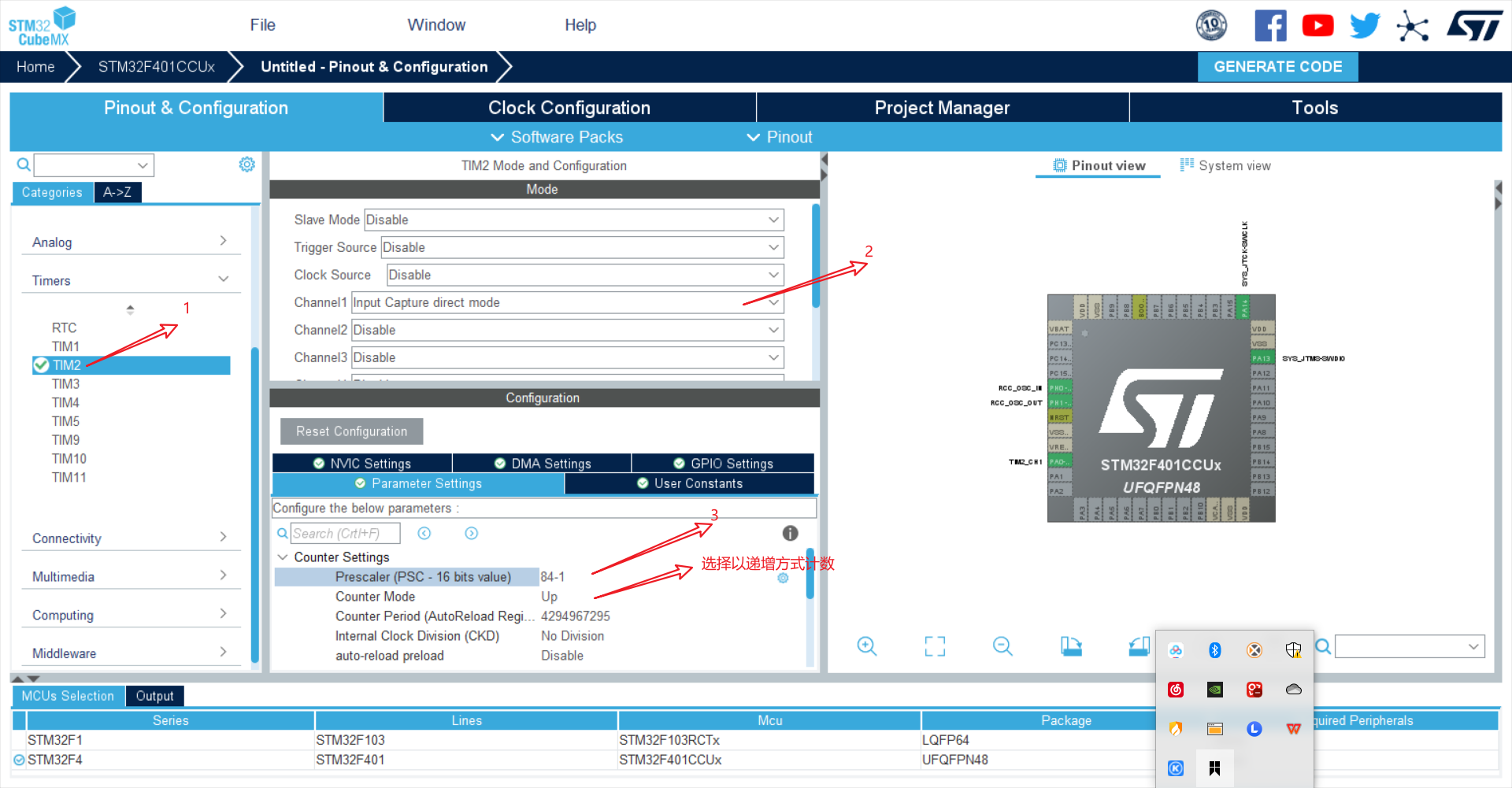
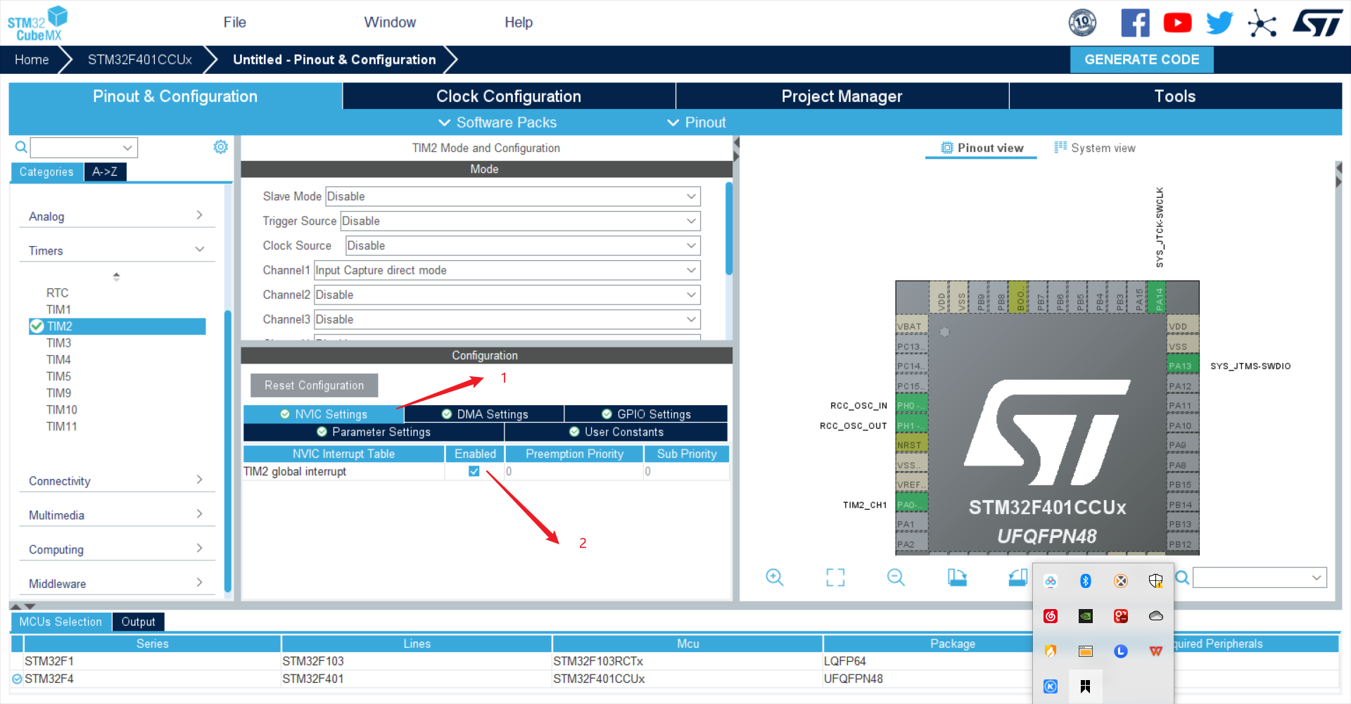
- Enable interrupt
- Turn on USART1 to display the collected data on the computer
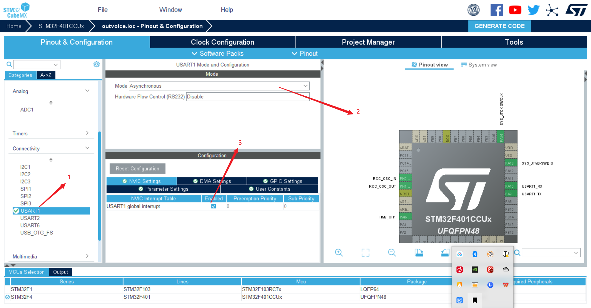
-
Generate code
-
Define some variables
uint8_t RxData[2];
uint16_t AD_Value = 0;
float Temp = 0;
uint8_t cTemp[20];
uint32_t capture_cnt = 0;
uint32_t capture_value1, capture_value2;
uint32_t pwm_cycle,hightime;
uint64_t duty;
float distance = 0;
double high_time;
double low_time;
double time;

float freq;

uint32_t cnt_buf[3];
-
Add this code in while (1)
-
HAL_UART_Receive_IT(&huart1,(uint8_t *)RxData,sizeof(RxData));//Serial port receiving switch(capture_cnt) { case 0: capture_cnt++; //Set TIM3 channel 1 capture rising edge __HAL_TIM_SET_CAPTUREPOLARITY( &htim2 , TIM_CHANNEL_1, TIM_INPUTCHANNELPOLARITY_RISING); //Enable TIM3 capture interrupt mode HAL_TIM_IC_Start_IT( &htim2 , TIM_CHANNEL_1 ); break; case 3: //Calculate the high level count value (TIM3 counter frequency 1MHz) if(capture_value2 >= capture_value1) hightime = capture_value2 - capture_value1; if(capture_value2 < capture_value1) { hightime = capture_value2 + (0xffff- capture_value1); } //According to the formula, the distance hightime/1000000.0 is the high-level time distance = hightime/10000.0*340/2.0; printf("%8.3f",distance); capture_cnt = 0; break; } //When the 00 command is received, ranging is carried out to give trig a high level if(RxData[0]=='0'&&RxData[1]=='0'){ HAL_GPIO_WritePin( GPIOA, GPIO_PIN_7,GPIO_PIN_SET); HAL_Delay(1); HAL_GPIO_WritePin( GPIOA, GPIO_PIN_7,0); RxData[1]='1'; } -
Write down timer interrupt
void HAL_TIM_IC_CaptureCallback( TIM_HandleTypeDef *htim ) { if( TIM2 == htim->Instance ) { if(HAL_TIM_ACTIVE_CHANNEL_1 == htim->Channel) { switch(capture_cnt){ case 1: //Gets the current count value capture_value1 = __HAL_TIM_GET_COMPARE( htim, TIM_CHANNEL_1 ); //Set capture falling edge // TIM_SET_CAPTUREPOLARITY( htim, TIM_CHANNEL_1, TIM_INPUTCHANNELPOLARITY_RISING); __HAL_TIM_SET_CAPTUREPOLARITY( htim, TIM_CHANNEL_1, TIM_INPUTCHANNELPOLARITY_FALLING); capture_cnt++; break; case 2: //Gets the current count value capture_value2 = __HAL_TIM_GET_COMPARE( htim, TIM_CHANNEL_1 ); //Stop input capture mode HAL_TIM_IC_Stop_IT( htim, TIM_CHANNEL_1); capture_cnt++; break; default: break; } } } }- Ultrasonic ranging can be used after burning