Routine introduction
Routine selection:
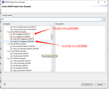
Selection criteria:
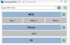
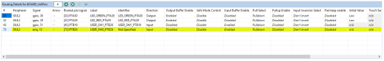
The level of peripherals after Dio opens is shown in the following figure:
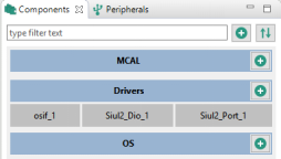
Siul2 opens the peripheral hierarchy as shown in Fig.
Use of GPIO
General GPIO
- Pin level control requires the following modules to be added to the diver:
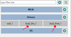
- Increase GPIO
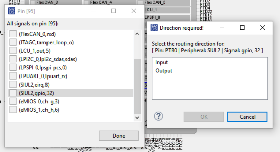
- Clicking on the SIUL2 module will display all pins with this feature, click on the pin you want to use, select the mode, and select the output direction. As shown below:
Introduction to Common API s
/*Operating pin high-low level conversion:*/
void Siul2_Dio_Ip_WritePin
(
    Siul2_Dio_Ip_GpioType * const   base, /* PORT Base address */
    Siul2_Dio_Ip_PinsChannelType   pin,  /* Corresponding pin number */
    Siul2_Dio_Ip_PinsLevelType      value/* Write 1 for high level output and 0 for low level output */
)

/*Operating pin high-low level conversion:*/
void Siul2_Dio_Ip_TogglePins
(   Siul2_Dio_Ip_GpioType * const base,
    Siul2_Dio_Ip_PinsChannelType pins )
PORT Explain:
S32K3 Each PORT Of GPIO Control separately by 16 bits high and 16 bits low, such as PORTA,Its high 16-bit and low 16-bit base addresses are different:
/** Peripheral PTA base address */
#define  PTA_L_HALF  ((Siul2_Dio_Ip_GpioType *)(&(IP_SIUL2->PGPDO0)))
#define  PTA_H_HALF  ((Siul2_Dio_Ip_GpioType *)(&(IP_SIUL2->PGPDO1)))
PINS Explain:
Be based on port The instructions mean that we can control 16 at once pin(High 16 bits or Low 16 bits), these bits (16 + 16)One-to-one correspondence with 32-bit pins, in the corresponding bit write 1, the corresponding pin is positioned at a high level, write 0, the corresponding pin is positioned at a low level.
Example:
#define LED_GREEN_PTA30_PIN     14u
Siul2_Dio_Ip_TogglePins(LED_GREEN_PTA30_PORT, 1 << LED_GREEN_PTA30_PIN);/*After 14 bits left, PTA30 pin level is flipped*/

//Read Pin Level
Siul2_Dio_Ip_PinsLevelType Siul2_Dio_Ip_ReadPin
(
    const Siul2_Dio_Ip_GpioType *  const base,  /* PORT Base address */
    Siul2_Dio_Ip_PinsChannelType  pin /* Corresponding pin number */
)

/* Read one PORT level at a time, configure only for input */
Siul2_Dio_Ip_PinsChannelType Siul2_Dio_Ip_ReadPins
(
    const Siul2_Dio_Ip_GpioType *  const base /* PORT Base address */
)
Configuration and use of GPIO interrupts
1. Add the following modules to the driver:
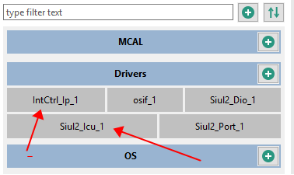
IntCtrl_Ip_1 is the basic configuration for universal interrupts, and this module needs to be added wherever interrupts are needed.
Siol2_Icu_1 is the interrupt of Siul2 module, that is, the interrupt configuration of GPIO.
2. New Pin

Set the corresponding pin to interrupt input mode, and leave the other settings as default.
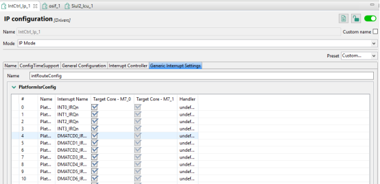
3. Configure IntCtrl_Ip_1 module
Depending on the requirements, this module has two configurations, one for IntCtrl_ There are two ways to configure the Ip module software.
Mode 1:
IntCtrl_Ip_1 Module keeps default configuration and does not add instance in Interrupt Controller
Corresponding interrupts in Generic Interrupt Settings do not require Handler s to be added
Open the interrupt you want to use separately with the software in the following section.
Mode 2:
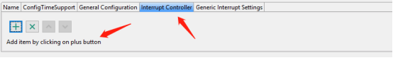
Use Interrupt Controller
First add an instance
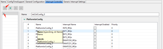
Enable interrupts you want to use
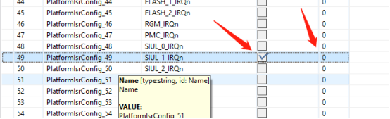
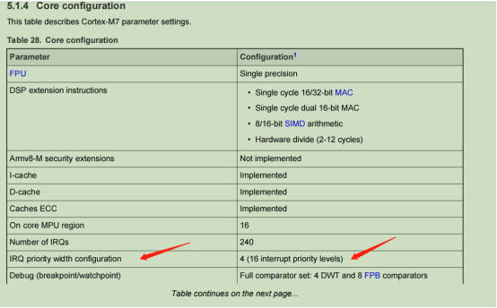
Note that the interrupt vector corresponding to the channel you are using is selected according to the reference data manual as shown in the following figure:
If necessary, you can set the priority of the interrupt, which defaults to 0.
The smaller the value of priority, the higher the priority. If the priority values set are the same, the order in the table is executed first. The maximum priority can be set at level 16 (4bit).
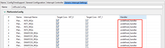
Add the name of the Handler correctly:
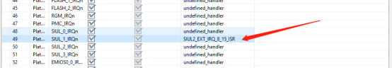
The name of the callback letter that follows needs to be peripheral_to the corresponding peripheral Ip_ Irq. C or peripheral_ Ip. The interrupt names in C are identical. For example, if GPIO requires Siul2_ Icu_ Ip_ Irq. SIUL2_in C file EXT_ IRQ_ 8_ 15_ ISR Fill in.
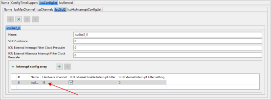
4. Configure Siul2_Icu_1 module
4.1 Configure the corresponding hardware interrupt channel according to the pin:
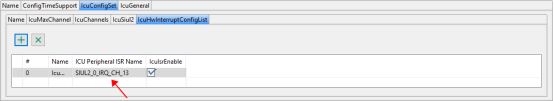
Note: Pin corresponds to interrupt channel, select pin corresponds to channel
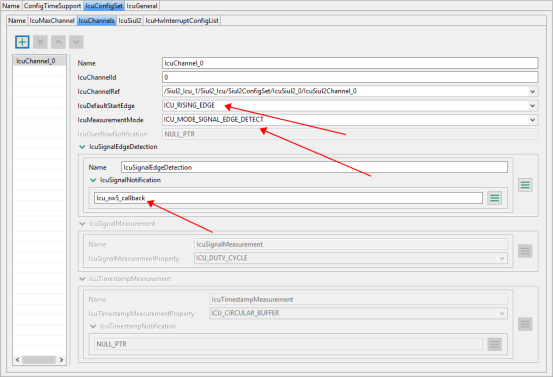
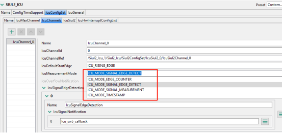
4.2 Select pin detection edge mode and develop callback function name:
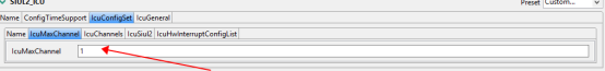
4.3 Of course, if there are multiple interrupts, you should pay attention to selecting the corresponding instance s and channels, one to one. Also remember to modify the maximum number of channels
5. Software Configuration
5.1 First, in main. Add the corresponding header file to c:
#include "Siul2_Icu_Ip.h"
#include "Siul2_Icu_Ip_Irq.h"
#include "IntCtrl_Ip.h"
#include "Clock_Ip.h"
5.2 Configure Clock
Clock_Ip_InitClock(&Mcu_aClockConfigPB[0]);
In MCU_ A lot of clocks are turned on in aClockConfigPB[0], such as SIUL0_CLK Clock)
5.3 IntCtrl_Ip Module Configuration
There are two ways to interrupt different peripheral s:
Mode 1:
Different peripheral s are individually enabled, as shown below for interrupts using GPIO modules alone.
IntCtrl_Ip_InstallHandler(SIUL_1_IRQn, &SIUL2_EXT_IRQ_8_15_ISR, NULL_PTR);
IntCtrl_Ip_EnableIrq(SIUL_1_IRQn);/*Enable Siul to interrupt*/
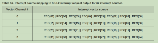
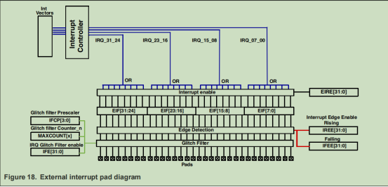
Different channels correspond to different Siul2 interrupt vectors, and there are four interrupt vectors to choose from:
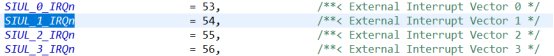
Select different interrupt vectors according to different interrupt channel requests:

Mode 2:
Call the following interfaces together to enable interrupts for all peripheral s
IntCtrl_Ip_Init(&IntCtrlConfig_0);
IntCtrl_Ip_ConfigIrqRouting(&intRouteConfig);
Function parameters are what we configure in our graphical configuration, in generate/src IntCtrl_ Ip_ Cfg. Two structures in c, which describe all breaks, correspond one to one to two representations in the graphical interface.
5.4 Siul2 Module Configuration
Initialize Icu Driver
Siul2_Icu_Ip_Init(0,&Siul2_Icu_Ip_0_Config_PB_BOARD_InitPeripherals);
The first parameter corresponds to instance
The second parameter, Siul2_Icu_Ip_0_Config_PB_BOARD_InitPeripherals in Sill 2_ Icu_ Ip_ SA_ BOARD_ InitPeripherals_ PBcfg. C, based on the Siol2_Icu_1 Module configuration generated code. So in the generate/src folder.
5.5 Icu interrupt and interrupt callback functions for corresponding channels of enabling pins
Siul2_Icu_Ip_EnableInterrupt(0,13);
Siul2_Icu_Ip_EnableNotification(0,13);
The first parameter above is instance, and the second parameter is the channel of the pin.
5.6 Initialization pin (can also be placed in front, independent of the previous initialization, no order)
Siul2_Port_Ip_Init(NUM_OF_CONFIGURED_PINS0, g_pin_mux_InitConfigArr0);
IO initialization.
5.7 Writing callback functions
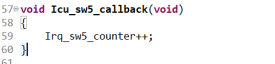
This callback function and Siol2_Icu_1 Consistent configurations in the module need to be written separately in the application layer. This function pointer is initialized in Icu (Siul2_Icu_Ip_Init (0, &Siul2_Icu_Ip_0_Config_PB_BOARD_InitPeripherals)); Is registered and is called automatically when a corresponding interrupt occurs.
Interrupt related API s
/*This API is located in IntCtrl_Ip.c is used to register a handler (pfNewHandler) for an interrupt (eIrqNumber).*/
void IntCtrl_Ip_InstallHandler( IRQn_Type eIrqNumber,
                               const IntCtrl_Ip_IrqHandlerType pfNewHandler,
                               IntCtrl_Ip_IrqHandlerType* const pfOldHandler

/* Enable corresponding interrupts (eIrqNumber) */
void IntCtrl_Ip_EnableIrq(IRQn_Type  eIrqNumber);

/* Icu Module Initialization */
Siul2_Icu_Ip_StatusType Siul2_Icu_Ip_Init(uint8 instance, const Siul2_Icu_Ip_ConfigType* userConfig)

/*Icu Module interrupt enable*/
void Siul2_Icu_Ip_EnableInterrupt(uint8 instance, uint8 hwChannel)

/*Icu Module user callback function enabled. User callback function is registered in function Siul2_Icu_Ip_Init()*/
void Siul2_Icu_Ip_EnableNotification(uint8 instance, uint8 hwChannel)

/* Set the detection status of the channel, up, down, and both sides */
Void Siul2_Icu_Ip_SetActivationCondition(uint8 instance, uint8 hwChannel, Siul2_Icu_Ip_EdgeType edge)
Matters needing attention
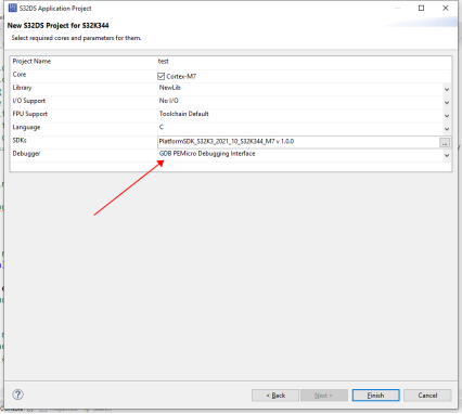
1. Debugger:
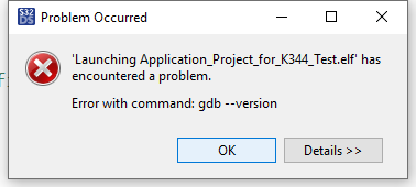
When debugging with the development board's micro USB, Debugger should be selected for the new project: GDB PEMicro DebuggeringInterface
Otherwise, the following error will be reported when burning with S32DS:
2. Debug
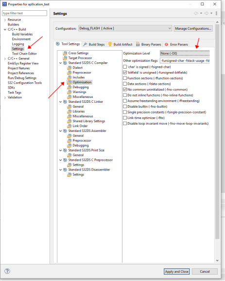
Optimizations are recommended to be turned off during debugging, otherwise breakpoint execution during debugging is inconsistent with reality: breakpoints that should not have progressed would have progressed.
Optimize Close Entry:
Right-click the project and click: properties
3. Legacy Issues
Icu Measurement mode has several modes, only signal edge detect ion is currently used, and several others have not been explored (no usage notes have been found in the documentation). Personally, I guess that the other modes are not for the GPIO module, but are more likely to be functions used by timer or ADC.
Another problem is that there is no high-level and low-level interrupt detection of GPIO, and the high-level interrupt is hardly needed, so it is not studied for the moment.