
§ 01 Arduino ATmega328 test circuit
according to Arduino access control man-machine interface debugging Version 1.0 Based on the design of the backplane based on groove beginer, according to DIY your Arduino UNO from 0 According to the design method, ATmega328 and the interface circuit are designed into a single circuit board, which can greatly simplify the composition of the system.
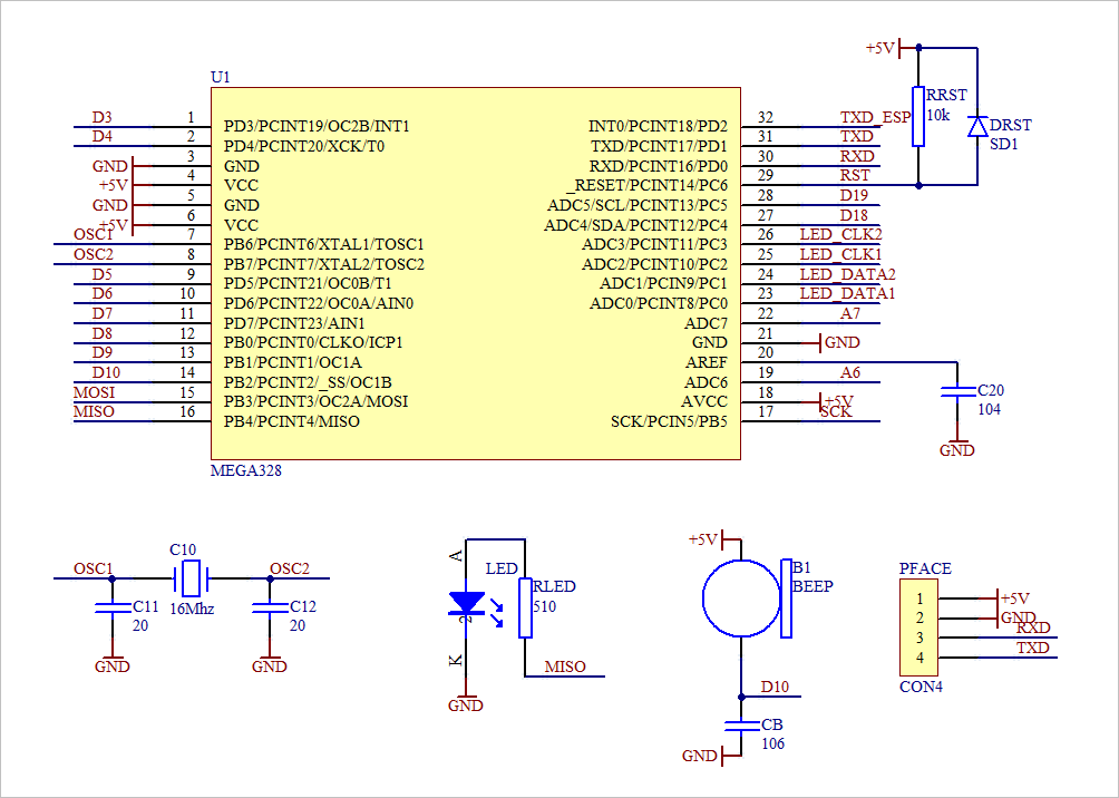
1. Circuit design
2. Interface description
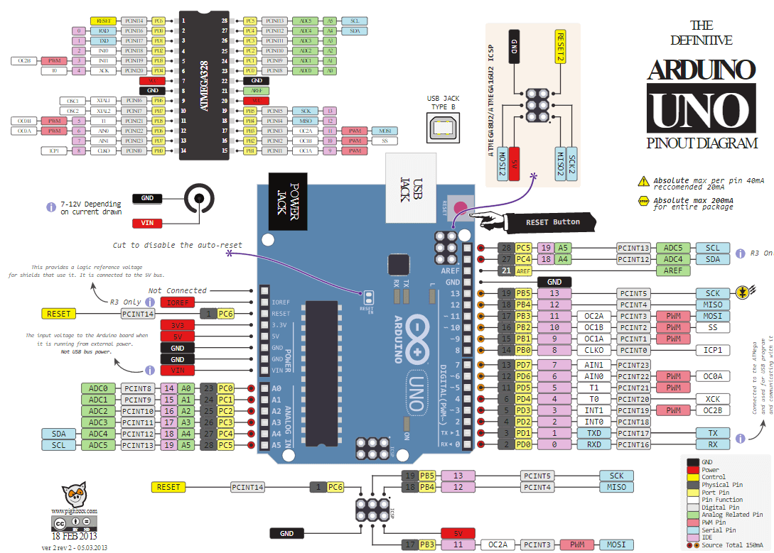
According to the definition of Arduino pin shown in the figure below and combined with the previous schematic design, the interfaces of key, LED module, steering gear, voice module, face module and ESP8266 module can be determined respectively.
(1) Key interface
The row scan and column scan of keys use D4, D5, D6, D7, D8, D9, D18 and D19 respectively. Refer to the following for the keyboard reading reference procedure:
/*
**==============================================================================
** TESTKEY.C:             -- by Dr. ZhuoQing, 2021-05-25
**
**==============================================================================
*/

//------------------------------------------------------------------------------

#define KEYLINE_1       4
#define KEYLINE_2       5
#define KEYLINE_3       6
#define KEYLINE_4       7
#define KEYCODE_1       8
#define KEYCODE_2       9
#define KEYCODE_3       18
#define KEYCODE_4       19

#define KEY_NULL        0xff
#define KEY_1           0x47
#define KEY_2           0x4B
#define KEY_3           0x4D
#define KEY_4           0x37
#define KEY_5           0x3B
#define KEY_6           0x3D
#define KEY_7           0x27
#define KEY_8           0x2B
#define KEY_9           0x2D
#define KEY_0           0x17
#define KEY_A           0x4E
#define KEY_B           0x3E
#define KEY_C           0x2E
#define KEY_D           0x1E
#define KEY_E           0x1D
#define KEY_F           0x1B

void keyLineSet(unsigned char ucLine) {
    if(ucLine & 0x1)    digitalWrite(KEYLINE_1, HIGH);
    else digitalWrite(KEYLINE_1, LOW);

    if(ucLine & 0x2)    digitalWrite(KEYLINE_2, HIGH);
    else digitalWrite(KEYLINE_2, LOW);

    if(ucLine & 0x4)    digitalWrite(KEYLINE_3, HIGH);
    else digitalWrite(KEYLINE_3, LOW);

    if(ucLine & 0x8)    digitalWrite(KEYLINE_4, HIGH);
    else digitalWrite(KEYLINE_4, LOW);
}

void keySetup(void) {
    pinMode(KEYLINE_1, OUTPUT);
    pinMode(KEYLINE_2, OUTPUT);
    pinMode(KEYLINE_3, OUTPUT);
    pinMode(KEYLINE_4, OUTPUT);
    pinMode(KEYCODE_1, INPUT_PULLUP);
    pinMode(KEYCODE_2, INPUT_PULLUP);
    pinMode(KEYCODE_3, INPUT_PULLUP);
    pinMode(KEYCODE_4, INPUT_PULLUP);

    keyLineSet(0x0);
}

unsigned char keyReadCode(void) {
    keyLineSet(0xe);
    if(keyCode() != 0xf) return 0x10 | keyCode();

    keyLineSet(0xd);
    if(keyCode() != 0xf) return 0x20 | keyCode();

    keyLineSet(0xb);
    if(keyCode() != 0xf) return 0x30 | keyCode();

    keyLineSet(0x7);
    if(keyCode() != 0xf) return 0x40 | keyCode();

    return 0xff;
}

unsigned char keyCode(void) {
    unsigned char ucCode;
    ucCode = 0x0;
    if(digitalRead(KEYCODE_1) == HIGH) ucCode |= 0x1;
    if(digitalRead(KEYCODE_2) == HIGH) ucCode |= 0x2;
    if(digitalRead(KEYCODE_3) == HIGH) ucCode |= 0x4;
    if(digitalRead(KEYCODE_4) == HIGH) ucCode |= 0x8;
    return ucCode;
}

//------------------------------------------------------------------------------
unsigned char Hex2Text(unsigned char ucCode) {
    if(ucCode < 10) {
        return '0' + ucCode;
    }

    return 'A' + ucCode - 10;

}

void SendHEX8(unsigned char ucCode) {
    Serial.write(Hex2Text(ucCode >> 4));
    Serial.write(Hex2Text(ucCode & 0xf));
}

//------------------------------------------------------------------------------
void setup(void) {
    Serial.begin(115200);
    keySetup();

}

//------------------------------------------------------------------------------
void loop(void) {
    delay(250);

    SendHEX8(keyReadCode());
    Serial.write("\r\n");
}

//==============================================================================
//                END OF THE FILE : TESTKEY.C
//------------------------------------------------------------------------------
(2) Dot matrix LED module interface
The four IO ports of the control dot matrix LED module are D14, D15, D16 and D17 respectively.
For LED module control, the reference program is:
/*
**==============================================================================
** TESTLED.C:             -- by Dr. ZhuoQing, 2021-05-25
**
**==============================================================================
*/

#define LED_DATA1       14
#define LED_DATA2       15
#define LED_CLK1        16
#define LED_CLK2        17

//------------------------------------------------------------------------------
unsigned char g_ucLEDBuffer[4][16];

void ledSetup(void) {
    int i, j;
    for(i = 0; i < 4; i ++) {
        for(j = 0; j < 16; j ++) {
            g_ucLEDBuffer[i][j] = 0x0;
        }

    }

    pinMode(LED_DATA1, OUTPUT);
    pinMode(LED_DATA2, OUTPUT);
    pinMode(LED_CLK1, OUTPUT);
    pinMode(LED_CLK2, OUTPUT);

    digitalWrite(LED_CLK1, HIGH);
    digitalWrite(LED_CLK2, HIGH);
    digitalWrite(LED_DATA1, HIGH);
    digitalWrite(LED_DATA2, HIGH);

}

void ledSetData12(unsigned char ucData12) {
    if(ucData12 & 0x1)
        digitalWrite(LED_DATA1, HIGH);
    else digitalWrite(LED_DATA1, LOW);

    if(ucData12 & 0x2)
        digitalWrite(LED_DATA2, HIGH);
    else digitalWrite(LED_DATA2, LOW);
}

void ledClock1(void) {
    digitalWrite(LED_CLK1, HIGH);       // clock up 7us
    digitalWrite(LED_CLK1, LOW);
}

void ledClock2(void) {
    digitalWrite(LED_CLK2, HIGH);
    digitalWrite(LED_CLK2, LOW);
}

void ledStart(void) {
    digitalWrite(LED_DATA1, LOW);
    digitalWrite(LED_DATA2, LOW);
    digitalWrite(LED_CLK1, LOW);
    digitalWrite(LED_CLK2, LOW);

}

void ledStop(void) {
    digitalWrite(LED_DATA1, LOW);
    digitalWrite(LED_DATA2, LOW);

    digitalWrite(LED_CLK1, HIGH);
    digitalWrite(LED_CLK2, HIGH);
    digitalWrite(LED_DATA1, HIGH);
    digitalWrite(LED_DATA2, HIGH);

}

void ledWriteData(unsigned char ucChar1, unsigned char ucChar2,
                  unsigned char ucChar3, unsigned char ucChar4) {

    unsigned char i;
    unsigned char ucMask;

    ucMask = 0x1;

    for(i = 0; i < 8; i++) {
        if(ucChar1 & ucMask) digitalWrite(LED_DATA1, HIGH);
        else digitalWrite(LED_DATA1, LOW);
        if(ucChar2 & ucMask) digitalWrite(LED_DATA2, HIGH);
        else digitalWrite(LED_DATA2, LOW);

        digitalWrite(LED_CLK1, HIGH);       // clock up 7us
        digitalWrite(LED_CLK1, LOW);

        if(ucChar3 & ucMask) digitalWrite(LED_DATA1, HIGH);
        else digitalWrite(LED_DATA1, LOW);
        if(ucChar4 & ucMask) digitalWrite(LED_DATA2, HIGH);
        else digitalWrite(LED_DATA2, LOW);

        digitalWrite(LED_CLK2, HIGH);       // clock up 7us
        digitalWrite(LED_CLK2, LOW);

        ucMask = ucMask << 1;

    }

}

//------------------------------------------------------------------------------
#define LEDCMD_ADD_INC          0x40
#define LEDCMD_ADD_SET          0x44
#define LEDCMD_MODE_CLOSE       0x80
#define LEDCMD_MODE_OPEN        0x8a

//------------------------------------------------------------
void ledWriteByteAll(unsigned char ucChar) {
    ledWriteData(ucChar, ucChar, ucChar, ucChar);
}

void ledWriteData16All(unsigned char ucData) {
    unsigned char i;

    ledStart();
    ledWriteByteAll(LEDCMD_ADD_INC);
    ledStop();

    ledStart();
    ledWriteByteAll(0xc0);
    for(i = 0; i < 16; i ++) {
        ledWriteByteAll(ucData);
    }

    ledStop();

    ledStart();
    ledWriteByteAll(LEDCMD_MODE_OPEN);
    ledStop();
}

//------------------------------------------------------------------------------
void ledWriteBuffer(void) {
    unsigned char i;

    ledStart();
    ledWriteByteAll(LEDCMD_ADD_INC);
    ledStop();

    ledStart();
    ledWriteByteAll(0xc0);
    for(i = 0; i < 16; i ++) {
        ledWriteData(g_ucLEDBuffer[0][i],
                     g_ucLEDBuffer[1][i],
                     g_ucLEDBuffer[2][i],
                     g_ucLEDBuffer[3][i]);
    }

    ledStop();
    ledStart();
    ledWriteByteAll(LEDCMD_MODE_OPEN);
    ledStop();
}

//------------------------------------------------------------------------------
#define LED_PIN         13
void setup(void) {
    ledSetup();

    pinMode(LED_PIN, OUTPUT);

}

//------------------------------------------------------------------------------
unsigned char ucCount = 0;
void loop(void) {
    int i, j;

    ucCount ++;
    if(ucCount & 0x1) digitalWrite(LED_PIN, HIGH);
    else digitalWrite(LED_PIN, LOW);

    for(i = 0; i < 4; i ++) {
        for(j = 0; j < 16; j ++) {
            g_ucLEDBuffer[i][j] = ucCount;
        }

    }

    ledWriteBuffer();
    delay(500);
}

//==============================================================================
//                END OF THE FILE : TESTLED.C
//------------------------------------------------------------------------------
For the test procedure of matching the key with the LED module, see Arduino access control man-machine interface debugging Version 1.0 The last routine.
(3) Steering gear interface
Use the MOSI (PB3) interface of ATmega328 and the corresponding Arduino interface D11.
according to Grove beginer kits basic experiment Arduino For the discussion of IO port controlling the steering gear, it is necessary to modify the register TCCR2B of timer 2 to modify the output frequency to 122.5Hz to meet the needs of steering gear control. Paste the following on the reference:
const int PWM_PIN   = 11;
void setup() {
    TCCR2B = TCCR2B & B11111000 | B00000110;
    pinMode(PWM_PIN, OUTPUT);
}
void loop() {
    delay(1000);
    analogWrite(PWM_PIN, 63);
    delay(1000);
    analogWrite(PWM_PIN, 31);
}
The above program outputs 31 (corresponding to 1ms) and 63 (corresponding to 2ms) respectively, which can control the steering gear to move from the leftmost to the rightmost.
| PWM pulse width | PWM setting | Actual output time (us) | Measured time (us) |
|---|---|---|---|
| 1ms | 31 | 0.992ms | 0.988 |
| 1.5ms | 47 | 1.504ms | 1.5ms |
| 2ms | 63 | 2.016ms | 2.01ms |
/*
**==============================================================================
** TESTPWM.C:             -- by Dr. ZhuoQing, 2021-05-30
**
**==============================================================================
*/

#define ON(pin)                 digitalWrite(pin, HIGH)
#define OFF(pin)                digitalWrite(pin, LOW)
#define VAL(pin)                digitalRead(pin)
#define IN(pin)                 pinMode(pin, INPUT)
#define OUT(pin)                pinMode(pin, OUTPUT)
const int LED_PIN = 13;

const int PWM_PIN       = 11;
const int SERVO_MID     = 47;
const int SERVO_LEFT    = 31;
const int SERVO_RIGHT   = 63;
void servoSetup(void) {

    TCCR2B = TCCR2B & B11111000 | B00000110;
    pinMode(PWM_PIN, OUTPUT);
    analogWrite(PWM_PIN, SERVO_MID);
}

//------------------------------------------------------------------------------
void setup(void) {
    pinMode(LED_PIN, OUTPUT);

    servoSetup();

}

//------------------------------------------------------------------------------
void loop(void) {
    analogWrite(PWM_PIN, SERVO_LEFT);
    delay(1000);
    analogWrite(PWM_PIN, SERVO_RIGHT);
    delay(1000);

}

//==============================================================================
//                END OF FILE : TESTPWM.C
//------------------------------------------------------------------------------
(4) Voice module interface
The voice module uses softwaresarial. Use the MISO and SCK pins of ATmega328 (corresponding to D12 and D13 respectively) as RX and TX.
The voice module uses 9600 baud rate. Send the code of the corresponding text through the software serial port to make a sound.
#include <SoftwareSerial.h>
//------------------------------------------------------------------------------
SoftwareSerial mySerial(12, 13);
void setup() {
    mySerial.begin(9600);
}
//------------------------------------------------------------------------------
void loop() {
    mySerial.write('U');
    delay(10);
}
The following program sends the pronunciation of "Zhuo Yikang".
/*
**==============================================================================
** TESTSERIAL.C:             -- by Dr. ZhuoQing, 2021-05-30
**
**==============================================================================
*/

#include <SoftwareSerial.h>

//------------------------------------------------------------------------------
SoftwareSerial ttsPort(12, 13);

void setup(void) {
    ttsPort.begin(9600);

}

//------------------------------------------------------------------------------
void loop(void) {
    ttsPort.write("\xd7\xbf\xd2\xbb\xbf\xb5");

    delay(1000);
}

//==============================================================================
//                END OF FILE : TESTSERIAL.C
//------------------------------------------------------------------------------
(5) Face recognition module interface
Unfinished to be continued
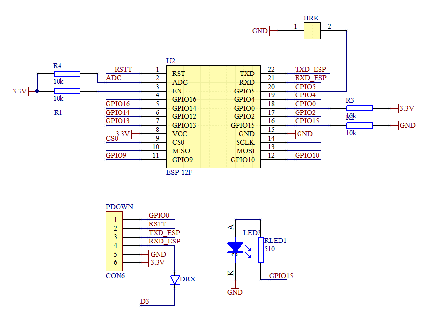
(6) ESP8266 interface
The ESP8266 is connected to the software serial of ATmega328. Use D2 and D3 ports. The baud rate of communication is 115200.
The following example program shows the process of sending and receiving.
/*
**==============================================================================
** UNORECEIVE.C:             -- by Dr. ZhuoQing, 2021-05-30
**
**==============================================================================
*/

#include <SoftwareSerial.h>

#define ON(pin)                 digitalWrite(pin, HIGH)
#define OFF(pin)                digitalWrite(pin, LOW)
#define VAL(pin)                digitalRead(pin)
#define IN(pin)                 pinMode(pin, INPUT)
#define OUT(pin)                pinMode(pin, OUTPUT)

SoftwareSerial ttsPort(12, 13);
SoftwareSerial wifiPort(2, 3);

//------------------------------------------------------------------------------
void setup(void) {
    char c;

    ttsPort.begin(9600);
    wifiPort.begin(115200);
    wifiPort.listen();
    wifiPort.setTimeout(500);
    Serial.begin(115200);

    //----------------------------------------------------------------------

}

//------------------------------------------------------------------------------
int count = 0;
String str;
void loop(void) {

    char c;
    char buf[256];

    ttsPort.listen();
    wifiPort.print("http://192.168.4.2:8000/lock/update/?type=LOCK&detail=AAAA\r");
    wifiPort.listen();

    while(1) {
        str = wifiPort.readString();
        Serial.print(str);

        if(wifiPort.available() == 0) break;

    }

    delay(2000);

}

//==============================================================================
//                END OF FILE : UNORECEIVE.C
//------------------------------------------------------------------------------
※ experimental summary ※
Unfinished to be continued
■ links to relevant literature:
- Arduino access control man-machine interface debugging Version 1.0
- DIY your Arduino UNO from 0
- Grove beginer kits basic experiment Arduino
● links to relevant charts: