CAN control RM motor
1. CAN overview
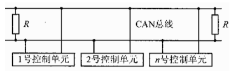
CAN is the abbreviation of controller area network (CAN). It is a serial communication network that CAN realize distributed real-time control.
The CAN bus is controlled by CAN_H and CAN_L is composed of two wires, and each device is mounted on the bus together.
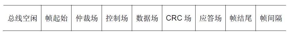
RoboMaster series motors also use can protocol for communication. The CAN protocol is complex. A complete data frame is composed of various parts in the figure below:
Each can attached to the CAN bus has its own unique ID. whenever a device sends a frame of data, other devices on the bus will check whether this ID is the object they need to receive data. If so, they will receive this frame of data. If not, they will ignore it.
1.1 arbitration venue
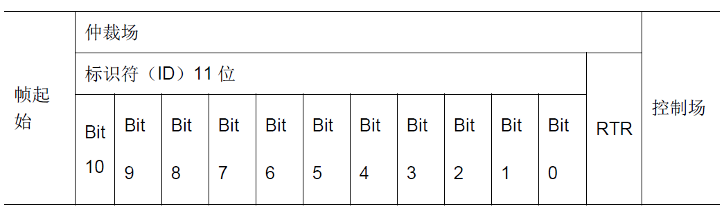
As shown in the above figure, the ID is stored in the arbitration field at the front of the data frame. The CAN ID is divided into standard ID and extended ID, and the length of the standard ID is 11 bits. If there are too many devices and the standard ID is not enough, the extended ID CAN be used. The length of the extended ID is 29 bits.
1.2 control field and data field
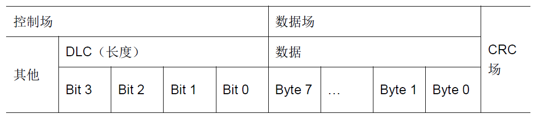
After judging that the frame data can be received through the ID, the DLC in the control field specifies the length of the frame data, and the size of the data in the data field is 8Byte, that is, 8 8 8-bit data. The valid data to be transmitted in a data frame of the CAN bus is actually this 8Byte (that is, the DLC length is generally set to 0x08).
2. RM C620 motor use
2.1 format of electric dispatching message
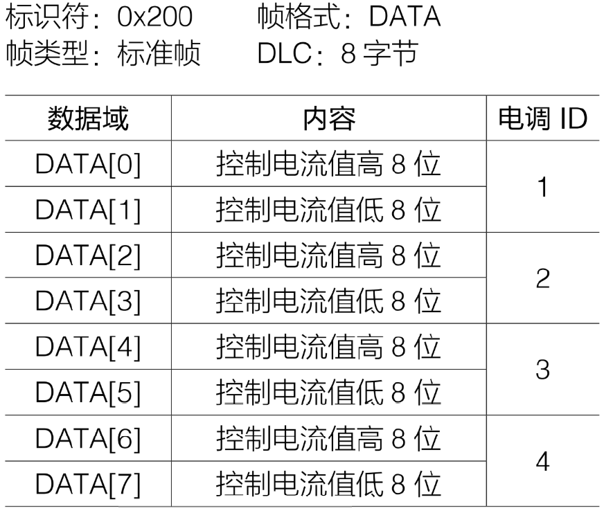
This is the sending message format of electric regulation, that is, if you want to send data to No. 1 to No. 4 electric regulation, control the output current of the motor, so as to control the motor speed, you need to set the ID of the sent CAN data frame to 0x200 according to the contents in the table, the 8Byte data in the data field is filled in the order of the high eight bits and the low eight bits of electric regulation 1 to 4, and the frame format and DLC are also set according to the contents in the table, Finally, send the data.
2.2 format of electric dispatching receiving message
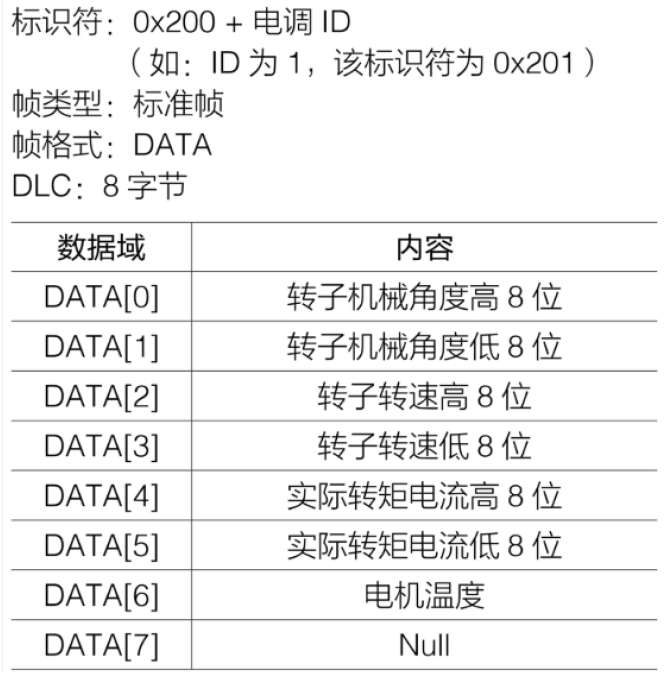
First, judge which data is sent by the electric dispatching according to the received ID. the manual stipulates that the ID of No. 1 electric dispatching is 0x201, No. 2 is 0x202, No. 3 is 0x203 and No. 4 is 0x204. After judging the data source, you can decode according to the data format in the manual, and obtain the rotor mechanical angle, rotor speed, torque current, motor temperature and other data of the motor by splicing the high eight bits and the low eight bits.
3. CAN configuration in cubeMX
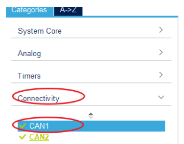
- First, open CAN1 in cubeMX, open CAN1 under Connectivity, and configure CAN1.
- In Mode, check Master Mode.
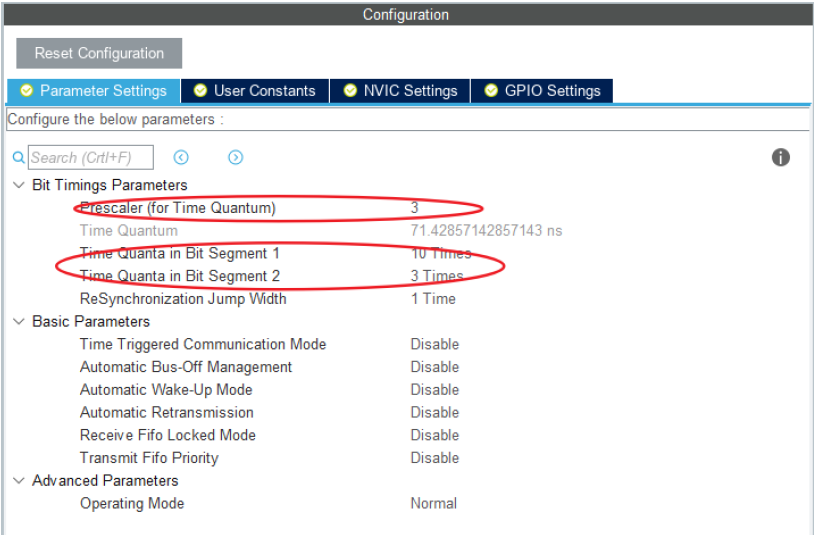
- In the Configuration interface, you need to configure the baud rate of can. After setting the prescaler, cubeMX will automatically complete the calculation of Time Quantum (abbreviated as tq), multiply tq by tbs1 (Time Quantum in bit segment 1), tbs2 (Time Quantum in bit segment 1) and RJW (ReSynchronization Jump Width), and the corresponding baud rate is 1M, This is the highest communication rate supported by the CAN bus.

4. CAN transmit function
CAN is provided in the program_ cmd_ Chassis function and CAN_cmd_gimbal function, used to send CAN signals to chassis motor and pan tilt motor to control motor movement.
4.1,CAN_cmd_chassis function
CAN_ cmd_ The input of the chassis function is the expected value of the driving current from motor 1 to motor 4, motor1 to motor4. The function will divide the expected value into the high eight bits and the low eight bits, put them into the can data field of 8Byte, and then add the ID (CAN_CHASSIS_ALL_ID 0x200), frame format, data length and other information to form a complete can data frame and send it to each electric regulator.
void CAN_cmd_chassis(int16_t motor1, int16_t motor2, int16_t motor3, int16_t motor4)
{
	uint32_t send_mail_box;

	chassis_tx_message.StdId = CAN_CHASSIS_ALL_ID;
	chassis_tx_message.IDE = CAN_ID_STD;
	chassis_tx_message.RTR = CAN_RTR_DATA;
	chassis_tx_message.DLC = 0x08;

	chassis_can_send_data[0] = motor1 >> 8;
	chassis_can_send_data[1] = motor1;
	chassis_can_send_data[2] = motor2 >> 8;
	chassis_can_send_data[3] = motor2;
	chassis_can_send_data[4] = motor3 >> 8;
	chassis_can_send_data[5] = motor3;
	chassis_can_send_data[6] = motor4 >> 8;
	chassis_can_send_data[7] = motor4;

	HAL_CAN_AddTxMessage(&CHASSIS_CAN, &chassis_tx_message, chassis_can_send_data, &send_mail_box);
}
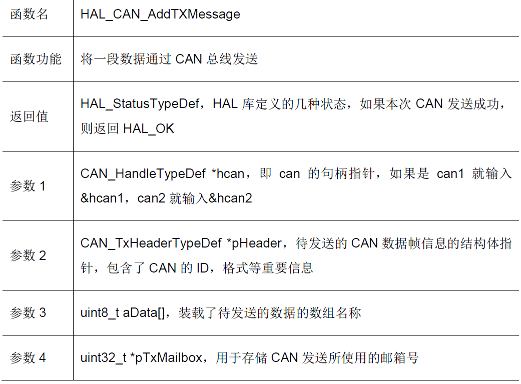
4.1.1 function Hal sent by can_ CAN_ AddTXMessage
HAL library provides the function of can transmission_ CAN_ AddTXMessage
HAL_StatusTypeDef HAL_CAN_AddTxMessage(CAN_HandleTypeDef *hcan,
CAN_TxHeaderTypeDef *pHeader, uint8_t aData[], uint32_t *pTxMailbox)
CAN_cmd_gimbal function is used to send control signals to PTZ motor and transmitting mechanism motor. The input parameters are yaw axis motor, pitch axis motor and expected driving current of transmitting mechanism motor yaw, pitch and shoot (rev is reserved value). The function will split the expected value into the upper eight bits and the eighth bit, put it into the can data field of 8Byte, and then add ID (CAN_GIMBAL_ALL_ID 0x1FF), Frame format, data length and other information to form a complete can data frame and send it to each electric regulator.
void CAN_cmd_gimbal(int16_t yaw, int16_t pitch, int16_t shoot, int16_t rev)
{
	uint32_t send_mail_box;
	gimbal_tx_message.StdId = CAN_GIMBAL_ALL_ID;
	gimbal_tx_message.IDE = CAN_ID_STD;
	gimbal_tx_message.RTR = CAN_RTR_DATA;
	gimbal_tx_message.DLC = 0x08; gimbal_can_send_data[0] = (yaw >> 8);
	gimbal_can_send_data[1] = yaw; gimbal_can_send_data[2] = (pitch >> 8);
	gimbal_can_send_data[3] = pitch; gimbal_can_send_data[4] = (shoot >> 8);
	gimbal_can_send_data[5] = shoot; gimbal_can_send_data[6] = (rev >> 8);
	gimbal_can_send_data[7] = rev;
	HAL_CAN_AddTxMessage(&GIMBAL_CAN, &gimbal_tx_message, gimbal_can_send_data, &send_mail_box);
}
5. CAN receive interrupt callback
HAL library provides can receive interrupt callback function HAL_CAN_RxFifo0MsgPendingCallback(CAN_HandleTypeDef *hcan), whenever can completes the reception of a frame of data, it will trigger a can reception interrupt processing function. After the reception interrupt function completes the processing of some registers, it will call the can reception interrupt callback function.
In the interrupt callback function, first judge whether the ID of the receiving object is the data from the received electric dispatching. After the judgment is completed, decode and load the data of the corresponding motor into the motor information array motor_chassis is in each corresponding bit.
void HAL_CAN_RxFifo0MsgPendingCallback(CAN_HandleTypeDef *hcan)
{
	CAN_RxHeaderTypeDef rx_header;
	uint8_t rx_data[8];
	HAL_CAN_GetRxMessage(hcan, CAN_RX_FIFO0, &rx_header, rx_data);
	switch (rx_header.StdId) {
		case CAN_3508_M1_ID:
		case CAN_3508_M2_ID:
		case CAN_3508_M3_ID:
		case CAN_3508_M4_ID:
		case CAN_YAW_MOTOR_ID:
		case CAN_PIT_MOTOR_ID:
		case CAN_TRIGGER_MOTOR_ID: {
			static uint8_t i = 0; //get motor id
			i = rx_header.StdId - CAN_3508_M1_ID;
			get_motor_measure(&motor_chassis[i], rx_data); break;
		}
		default: { break; }
	}
}
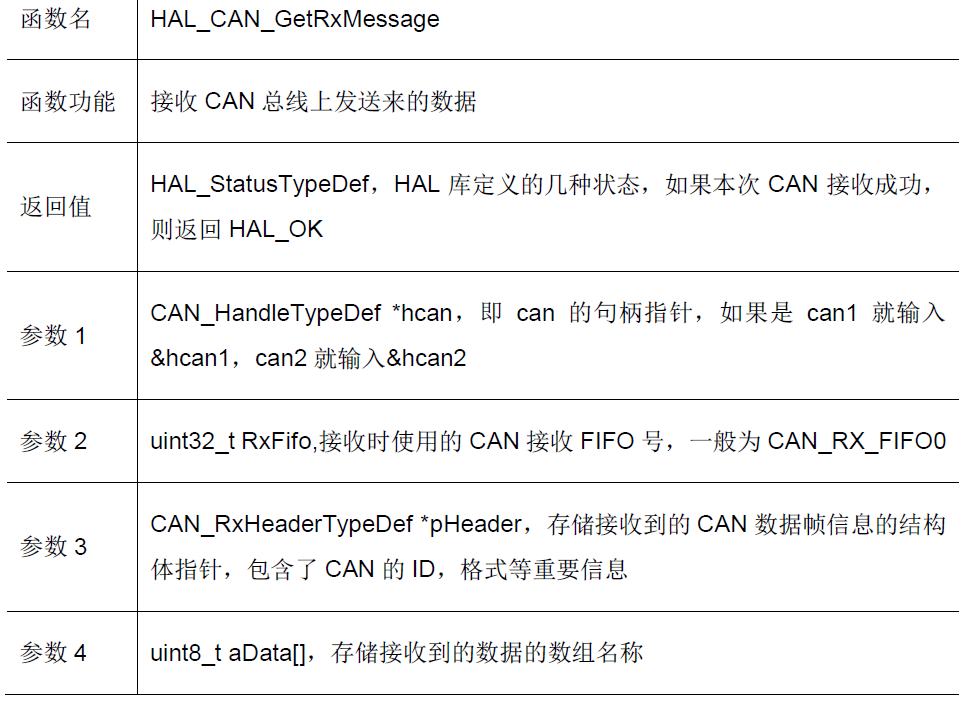
5.1 receiving function HAL_CAN_GetRxMessage
When receiving, the receiving function HAL provided by HAL library is called_ CAN_ GetRxMessage
HAL_StatusTypeDef HAL_CAN_GetRxMessage(CAN_HandleTypeDef *hcan,
uint32_t RxFifo, CAN_RxHeaderTypeDef *pHeader, uint8_t aData[])
motor_chassis is motor_measure_t type array, which contains motor rotor angle, motor rotor speed, control current, temperature and other information.
typedef struct {
	uint16_t ecd;
	int16_t speed_rpm;
	int16_t given_current;
	uint8_t temperate;
	int16_t last_ecd;
} motor_measure_t;
5.1.1. Decoding function get_motor_measure
The decoding function actually completes the work of splicing the received data according to the high eight bits and the low eight bits, so as to obtain the parameters of the motor.
#define get_motor_measure(ptr, data) \
	{ \
			(ptr)->last_ecd = (ptr)->ecd; \
			(ptr)->ecd = (uint16_t)((data)[0] << 8 | (data)[1]); \
			(ptr)->speed_rpm = (uint16_t)((data)[2] << 8 | (data)[3]); \
			(ptr)->given_current = (uint16_t)((data)[4] << 8 | (data)[5]); \
			(ptr)->temperate = (data)[6]; \
	}
To be continued.....