preface
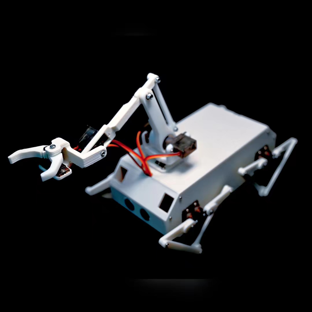
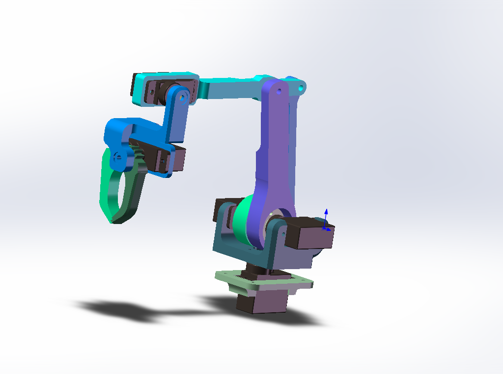
This paper mainly makes a simple modeling and kinematic analysis of a six degree of freedom manipulator. This mechanical arm model comes from dog king. I have made many improvements to the model in the actual production process. I have designed a 5-free mechanical arm, all of which use 9g steering gear. The actual measurement is feasible, which greatly reduces the production cost and difficulty.
1, Kinematics analysis of manipulator
1. Institutional analysis:
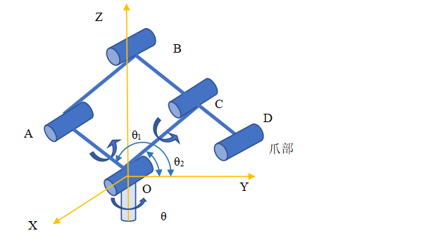
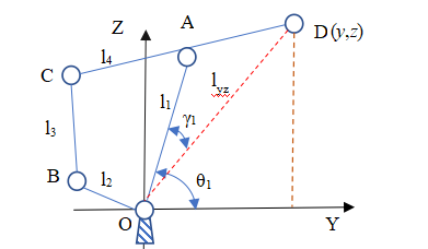
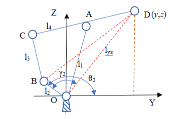
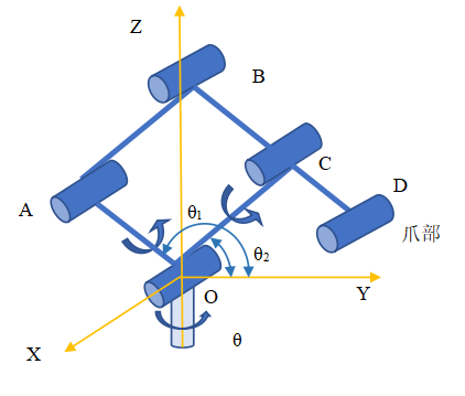
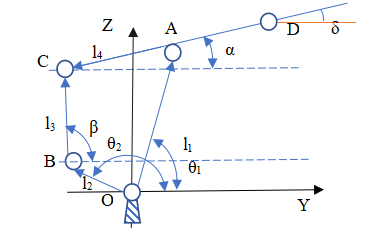
The mechanism is divided into two main structures: manipulator and end effector (claw). The two parts operate independently. Under the combined action of series connection, the final end trajectory is obtained. Manipulator part: abstract the mechanical structure and get the schematic diagram of the manipulator mechanism, as shown in the figure below. The plane of quadrilateral OABC is perpendicular to XOY plane. The structure is driven and controlled by three motors, which can make the manipulator rotate around any straight line in the XOY plane (a pair of motors on the connecting rod) θ 1,2, the rotating shaft is straight θ Determine), Z-axis rotation (single motor on chassis).
2. Forward solution analysis of manipulator (find the projection position of point D in YOZ plane)
Because the structure of the claw is relatively simple, the mechanical arm is mainly studied here. It is assumed that the plane enclosed by OABC coincides with the YOZ plane θ= 0, the positive included angles of rod OA, OC and Y axis are respectively θ 1,2. Present hypothesis θ= 0, analyze quadrilateral OABC:

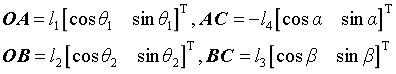
According to the closed quadrilateral OABC, the vector as shown in the figure is established to obtain the vector equation:
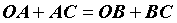
Assumed rod length: l1=OA, l2=OB, l3=BC, l4=CA, l5=AD
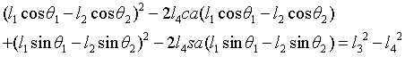
Get the equations
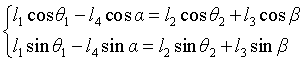
The coordinates of point D projected on the YOZ plane are:

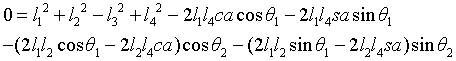
Elimination of equations β Get:

Sorting:
among
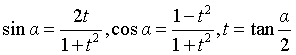
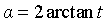
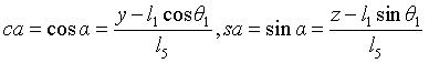
According to the triangular transformation formula, set:
Generation simplification:
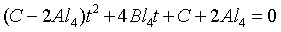
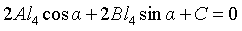
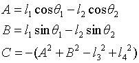
Sorting:
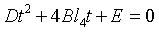
among
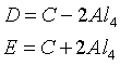
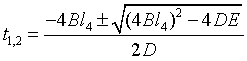
Solution:
- 90 ° ≤ α ≤ 90 °, as an option α Basis for. take α The coordinates of point D are obtained by substitution.
3. Inverse solution analysis of manipulator (given the position of point D, calculate the driving angle)
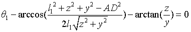
3.1 solution θ one
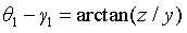
As shown in the figure above, the angular relationship can be obtained by constructing triangular OAD:
According to the cosine theorem:
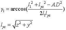
The position of point D (y,z) and θ 1. Relationship between:
3.2.1 solution θ 2 (method I)
Similarly, a triangular OBD is constructed to obtain the angular relationship:
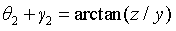
According to the cosine theorem:

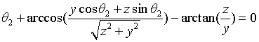
The position of point D (y,z) and θ 2. Relationship between:
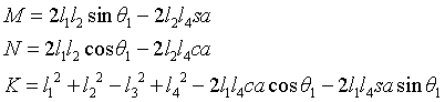
3.2.2 solution θ 2 (method 2)

Substitution formula:
Sorting:
Simplified:

among
According to the triangular transformation formula, set:
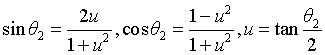
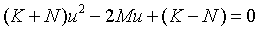
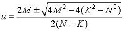
Solution
4. Supplement
1. Consider the positive solution supplement of base motor

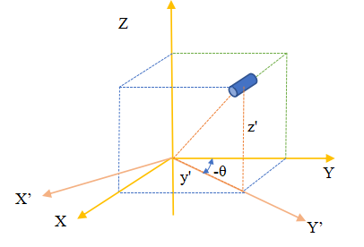
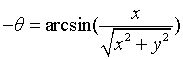
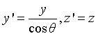
The position track of the end position in the YOZ plane is obtained in the above documents. Combined with the reality of the subject, considering the overall rotation of the manipulator around the Z axis, the above figure is obtained. (in order to facilitate the drawing, it is selected to turn from the Y axis to the X axis. Generally, it is assumed that turning from the X axis to the Y axis is positive.) in robotics, the determination of the end position is closely related to the order of establishing the rotating axis. Here, the rotational motion around the x-axis is given priority, and finally the rotation around the z-axis is considered. During the rotation of the rotating base motor, the coordinate system YOZ also rotates to obtain the coordinate system y'OZ. At this time, the coordinates of the manipulator in the y'OZ plane are:

The coordinates in the YOZ plane are:
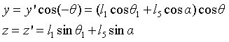
The coordinates of the manipulator in the x direction are:

2. Supplement of inverse solution considering base motor
When solving the inverse solution, it is assumed that the coordinates of point D are (x,y,z), and the rotation angle of the base motor will be given priority θ:
solve θ In case of 1 and 2, the Y coordinate shall be processed:
take

Substitute the previous document to get θ 1,2
3. Consider claw
The motor of the claw does not have a significant impact on the end position. Motor 1 can be regarded as making the claw move in a circle around point D. motor 2 is to change the grasping angle, and motor 3 is the control force, which is generally adjusted according to the actual situation.
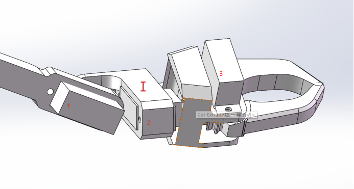
Here, assuming that the initial state is that plane I is coplanar with rod CD, it is necessary to keep plane I always parallel to the horizontal plane. Based on this situation, the angle of motor 1 is controlled.
As can be seen from the above figure, the control angle of motor 1 δ=α, Therefore, in the forward and inverse solution, the angle still needs to be α (variable name) for output.
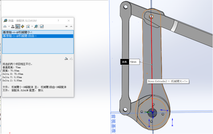
5. Example verification
Assignment of rod length: l1=OA=70mm, l2=OB=20mm, l3=BC=75mm, l4=CA=20mm, l5=AD=54.38mm
Position: y=49.51,z=50.38
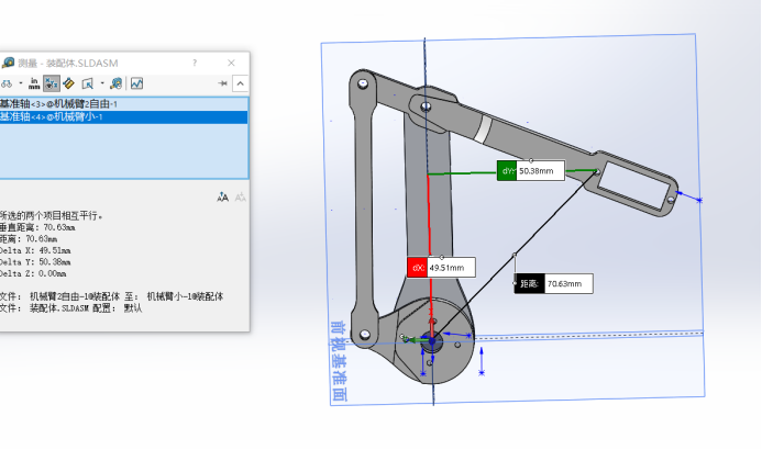
Angle: th1=90 °, th2=172.68 °
MATLAB calculation actual solution:
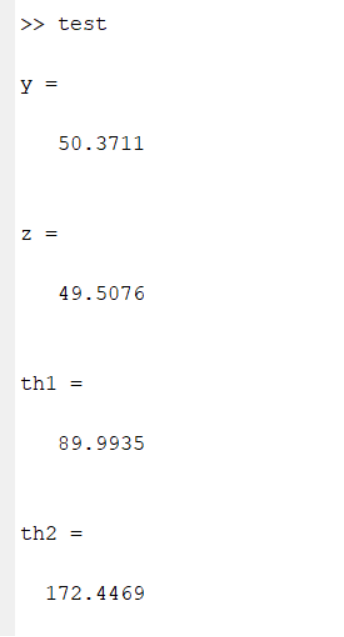
The code is as follows:
test.m
clear,clc
%input data
t1=[44.77,37.27,37.23,81.53,90];
t2=[22.44,3.98,87.62,34.08,140.81]+90;
y=[57.74,35.4,128.44,19.7,66.2];
z=[-28.17,-32.8,14.43,-8.08,111];
th1=t1/180*pi;th2=t2/180*pi;

for i=1:length(th1)
%Positive solution test
[yr(i),zr(i)]=forward(th1(i),th2(i));
%Inverse solution test
[th1r(i),th2r(i)]=inverse(y(i),z(i));
end
atan2(z,y)
testh=[t1;th1r;t2;th2r]
tesx=[y;yr;z;zr]
forward.m
function [x,y]=forward(th1,th2)
%Scale assignment
l1=70;l2=20;l3=75;l4=20;l5=77.88;
A=l1*cos(th1)-l2*cos(th2);
B=l1*sin(th1)-l2*sin(th2);
C=-(A*A+B*B-l3*l3+l4*l4);
D=C-2*A*l4;
E=C+2*A*l4;
t1=(-4*B*l4+sqrt(16*B*B*l4*l4-4*D*E))/2/D;
%t2=(-4*B*l4-sqrt(16*B*B*l4*l4-4*D*E))/2/D;
alp1=2*atan(t1);
x=l1*cos(th1)+l5*cos(alp1);
y=l1*sin(th1)+l5*sin(alp1);
end
inverse.m
function [th1,th2,del]=inverse(y,z)
%Scale assignment
l1=70;l2=20;l3=75;l4=20;l5=77.88;
th1=acos((l1*l1+y*y+z*z-l5*l5)/2/l1/sqrt(y*y+z*z))+atan2(z,y);
M=2*l1*l2*sin(th1)-2*l2*l4*(z-l1*sin(th1))/l5;
N=2*l1*l2*cos(th1)-2*l2*l4*(y-l1*cos(th1))/l5;
K=l1*l1+l2*l2-l3*l3+l4*l4-2*l1*l4*(y-l1*cos(th1))/l5*cos(th1)-2*l1*l4*(z-l1*sin(th1))/l5*sin(th1);
del=4*M*M-4*(K^2-N^2);
u1=(2*M+sqrt(4*M*M-4*(K^2-N^2)))/2/(N+K);
% u2=(2*M-sqrt(4*M*M-4*(K^2-N^2)))/2/(N+K);
th2=2*atan(u1);
th1=rad2deg(th1);
th2=rad2deg(th2);
end
6. It is realized in single chip microcomputer
stm32 series single chip microcomputer is used for the main control. 16 pwm steering gears can be driven to work at the same time through the communication between IIC and pca9685 chip. Before installing the steering gear, the flag bit should be set in the program. I use the installation position of big arm and small arm at 90 degrees. Power on before installation to reset the steering gear. When using the manipulator, in order to prevent the steering gear from getting stuck and burning out, it is necessary to limit the amplitude in the program.
void inverse(float y,float z){
float l1=70,l2=20,l3=75,l4=20,l5=77.94;
float th1,M	,N,K,u1,th2;

th1=acos((l1*l1+y*y+z*z-l5*l5)/2/l1/sqrt(y*y+z*z))+atan2(z,y);
M=2*l1*l2*sin(th1)-2*l2*l4*(z-l1*sin(th1))/l5;
N=2*l1*l2*cos(th1)-2*l2*l4*(y-l1*cos(th1))/l5;
K=l1*l1+l2*l2-l3*l3+l4*l4-2*l1*l4*(y-l1*cos(th1))/l5*cos(th1)-2*l1*l4*(z-l1*sin(th1))/l5*sin(th1);
//del=4*M*M-4*(K^2-N^2);
u1=(2*M+sqrt(4*M*M-4*(K*K-N*N)))/2/(N+K);
//u2=(2*M-sqrt(4*M*M-4*(K^2-N^2)))/2/(N+K);
th2=2*atan(u1);
th3=180/3.1415926*th1;
th4=180/3.1415926*th2;
if (   th3 <=180&&th3>=0){
PCA_MG9XX(8,th3,th3,0,2);	}
if(th4<=180&&th4>=0){
PCA_MG9XX(9,180-th4,180-th4,0,2);}

}
1. Mobile phone remote control operation
 2. Visual following
summary
The above is the main content of this article. In this paper, the kinematics algorithm is simply used to realize the movement of the manipulator. For remote control operation and visual follow, I only use the inverse solution method. If we want to realize attitude self stabilization, we need to use the gyroscope module. At this time, we need to use the combination of forward solution and inverse solution. If you want to achieve more accurate operation, you will use a lot of kinematic algorithms.