1, Environment introduction
Compiling integrated development environment: IAR
MCU: CC2530(ZigBee)
Programming language: C language
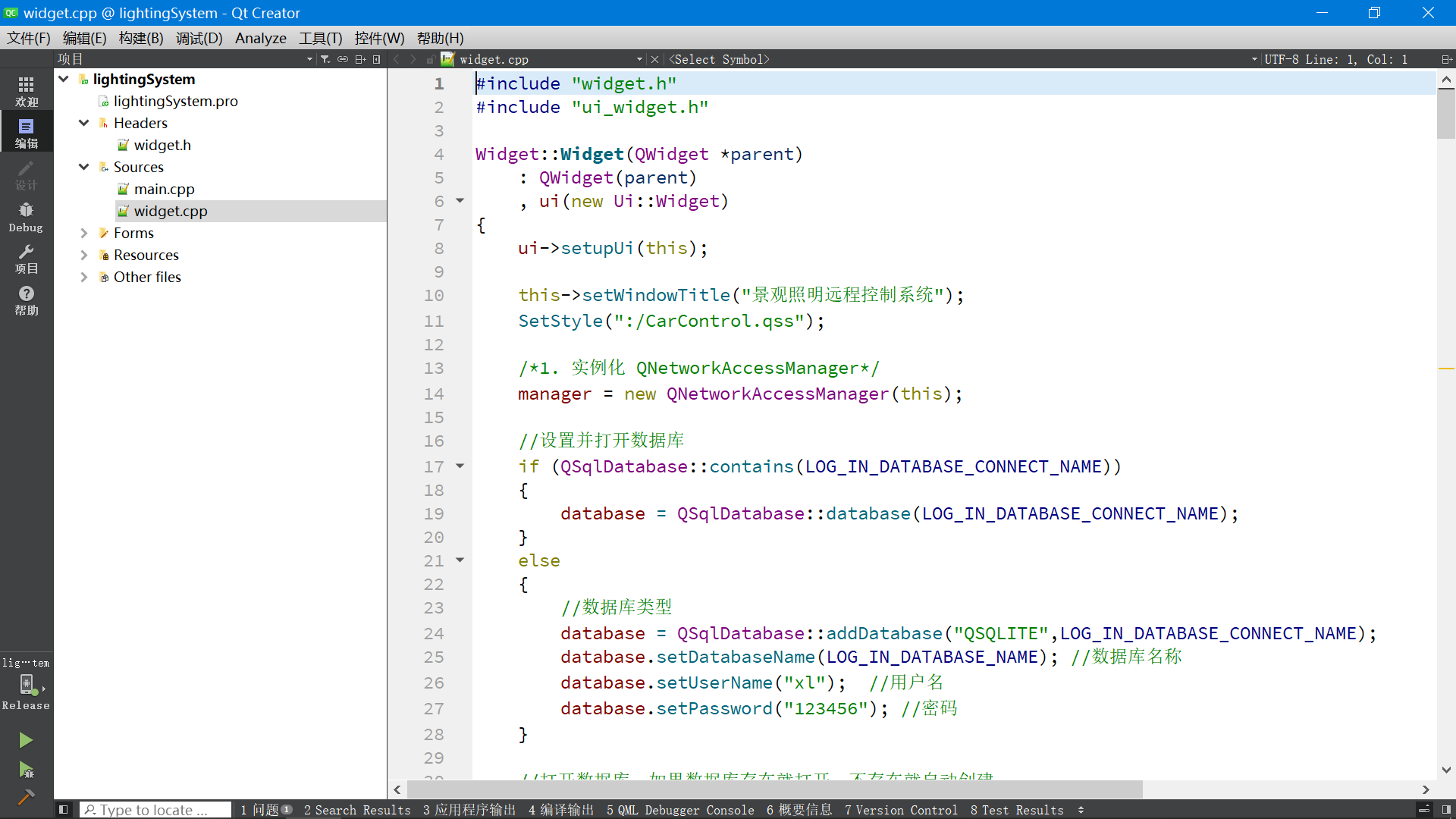
Mobile APP: QT design is adopted, and the program supports cross platform compilation and operation (Android, IOS, Windows and Linux can be compiled and run, and the corresponding QT environment on the platform is built, which has been explained in the blog before)
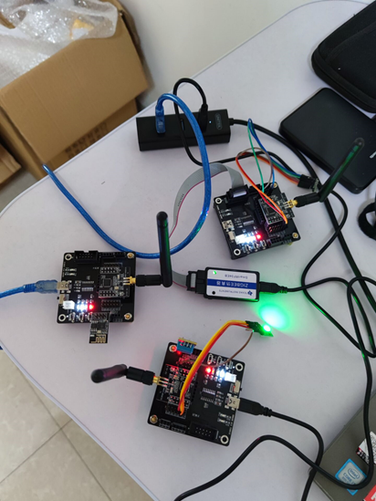
The hardware includes three sets of CC2530 development boards (one coordinator and two nodes), one ESP8266 serial port WIFI, one DHT11 temperature and humidity sensor, one RGB colorful lamp and one BH1750 light intensity detection sensor
Download address of complete project source code: https://download.csdn.net/download/xiaolong1126626497/19730948
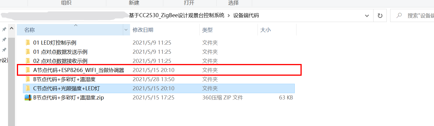
The data package includes: CC2530 coordinator source code, two node source code, mobile APP source code, Windows host computer source code, mobile APP executable file, IAR downloader driver, IAR data, etc.

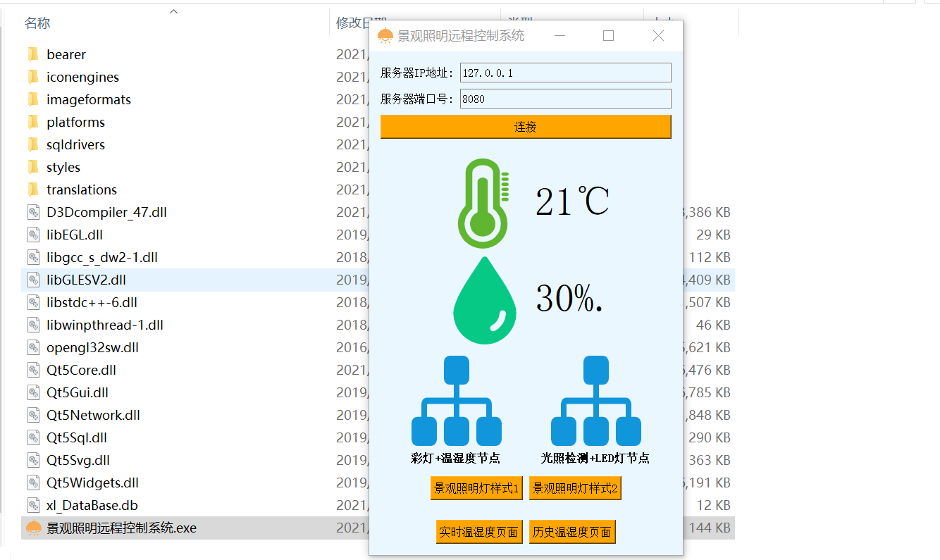
2, Function introduction
This is a landscape lighting control system designed based on CC2530, which includes three CC2530 nodes (i.e. three CC2530 development boards).
The three CC2530 development boards are called nodes A, B and C.
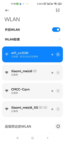
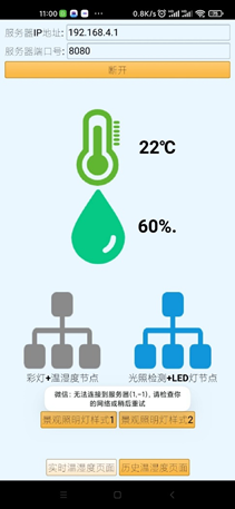
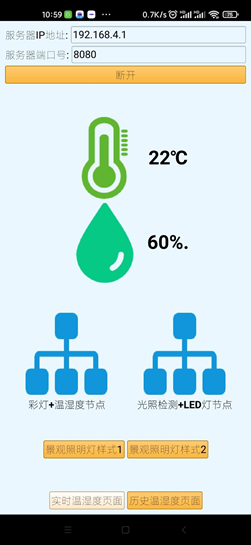
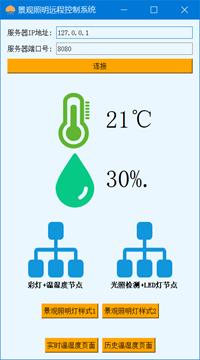
Node A: as a coordinator, it can receive the data uploaded by BC node; Module a is equipped with an ESP8266 WIFI module, which can be connected to the mobile APP, upload the temperature and humidity data from the BC node, and then upload it to the mobile APP for display. If node a does not receive the data of nodes B and C within a certain time, it will notify the mobile APP and tell the user that nodes B and C have been disconnected.
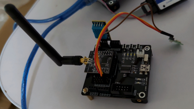
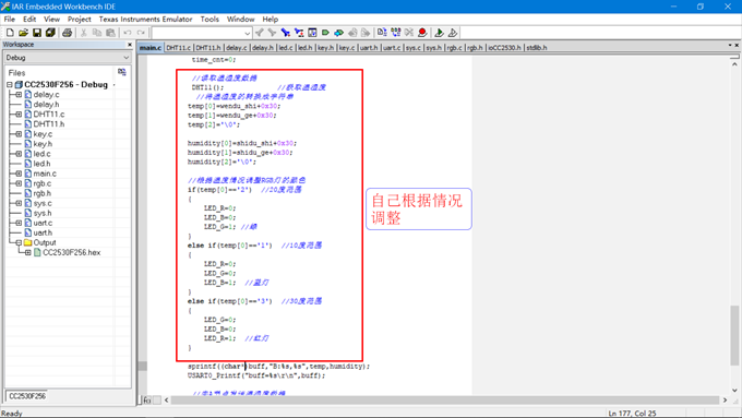
Node B: as the RGB colorful lamp + temperature and humidity detection node, the color of the current RGB lamp will be adjusted according to the current temperature and humidity, which is used to tell the tourists of the scenic spot about the temperature and humidity of the current scenic spot, and the collected temperature and humidity will also be transmitted to node A through CC2530.
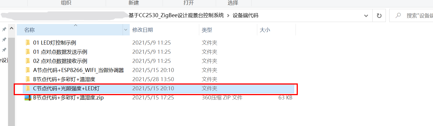
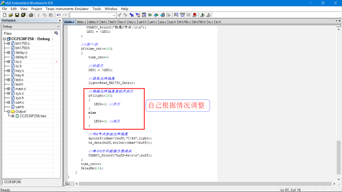
Node C: light intensity detection + LED lamp node. The LED lights here simulate the street lights in the scenic area. The mobile APP can control the switch of the LED lights. If it is daytime, the LED lights will be turned off automatically, and the weather will turn dark and on automatically. You can also design the time and turn off the lights regularly.
3, Related hardware introduction
3.1 DTH11 temperature and humidity sensor
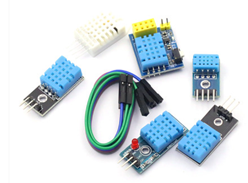
DHT11 digital temperature and humidity sensor is a temperature and humidity composite sensor with calibrated digital signal output. It applies special digital module acquisition technology and temperature and humidity sensing technology to ensure that the product has high reliability and excellent long-term stability. The sensor includes a resistive humidity sensing element and an NTC temperature measuring element, which are connected with a high-performance 8-bit single chip microcomputer. Therefore, the product has the advantages of excellent quality, ultra fast response, strong anti-interference ability and high cost performance. Each DHT11 sensor is calibrated in an extremely accurate humidity calibration chamber. The calibration coefficients are stored in OTP memory in the form of program, and these calibration coefficients should be called during the processing of detection signal inside the sensor. Single line serial interface makes system integration simple and fast. Its ultra-small size and extremely low power consumption make it the best choice in this kind of applications and harsh applications. The product is packaged with 4-pin single row pins, which is convenient for connection.
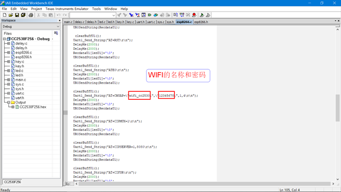
3.2 ESP8266 WIFI
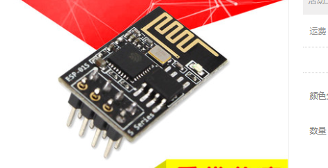
ESP8266 series wireless module is a cost-effective WIFI SOC module, which supports standard IEEE802 11b / g / N protocol, built-in complete TCP/IP protocol stack. Users can use this series of modules to add networking functions to existing devices, or build an independent network controller.
Can be excellent
ESP8266EX chip has built-in ultra-low power Tensilica L106 32-bit RISC processor. The CPU clock speed can reach 160 MHz at most. It holds real-time operating system (RTOS) and Wi Fi protocol stack, and can apply up to 80% of processing energy to programming and development.
Highly integrated
ESP8266 chip is highly integrated with antenna switch, RF balun, power amplifier, low noise receiving amplifier, filter and other RF modules. The module is small in size, especially suitable for product design with limited space.
Complete certification
RF certification: SRRC, FCC, CE-RED, KCC, TELEC/MIC, IC and NCC certification;
Environmental protection certification: RoHS, REACH;
Reliability certification: HTOL, HTSL μ HAST,TCT,ESD.
Rich product applications
ESP8266 module can provide Wi Fi connection function for external host MCU through ESP-AT command firmware; It can also run as an independent Wi Fi MCU. Users can develop products with Wi Fi connection function through RTOS based SDK. Users can easily realize out of the box cloud connection, low-power operation mode, and Wi Fi security support including WPA3.
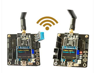
3.3 CC2530
CC2530 is a true system on chip (SoC) solution for 2.4-GHz IEEE 802.15.4, ZigBee and RF4CE applications. It can build powerful network nodes with very low total material cost.
CC2530 combines the excellent performance of leading RF transceiver, industry standard enhanced 8051 CPU, programmable flash memory in the system, 8-KB RAM and many other powerful functions. CC2530 has four different flash memory versions: CC2530F32/64/128/256, with 32/64/128/256KB flash memory respectively. CC2530 has different operation modes, which makes it especially suitable for systems with ultra-low power consumption requirements. The short switching time between operation modes further ensures low energy consumption.
CC2530F256 combines the industry-leading ZigBee protocol stack of Texas Instruments ™), Provides a powerful and complete ZigBee solution.
CC2530F64 combines the gold unit RemoTI of Texas Instruments to better provide a powerful and complete ZigBee RF4CE remote control solution.
3.4. RGB colorful lamp
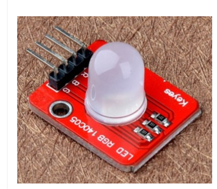
Color: full color red, green and blue
Brightness: Highlight
Voltage: 5V
Input: digital level
The principle of three primary colors displays multiple colors
Full color display through PWM port control
3.5 BH1750
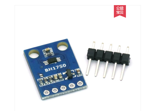
bh1750 is a 16 bit digital output type, ambient light intensity sensor.
4, Introduction to node hardware + Mobile APP
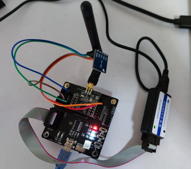
4.1 # node C: photosensitive sensor + LED light control
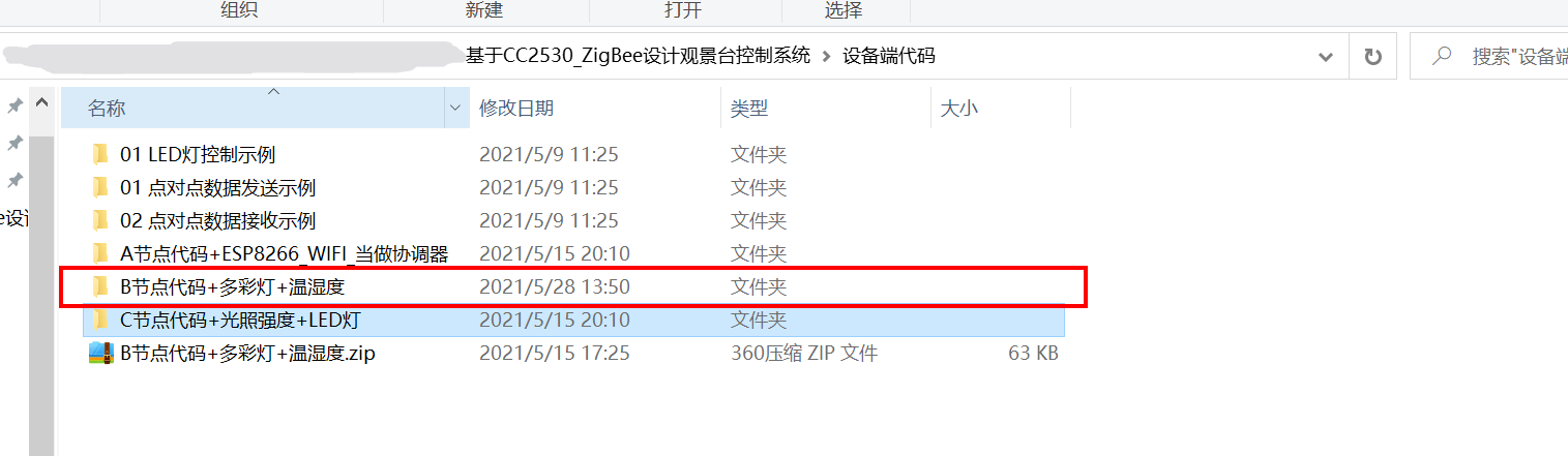
4.2 # node B: colorful lamp + temperature and humidity
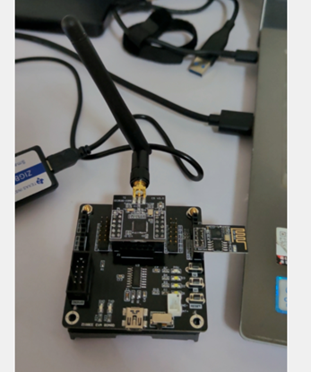
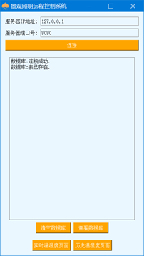
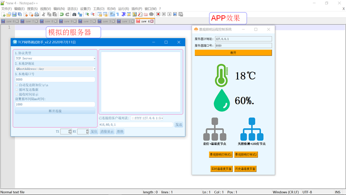
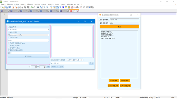
4.3 node A: WIFI + APP
4.4 effect of mobile APP interface
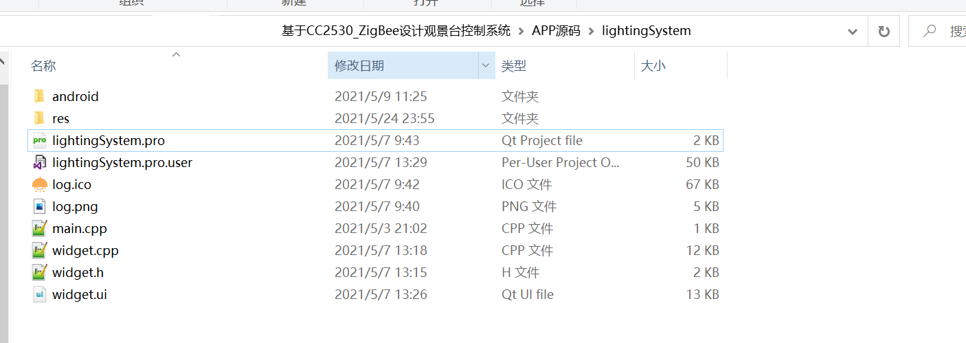
5, Mobile APP host computer source code
6, CC2530 node source code
There are many node source codes. Here are some key codes.
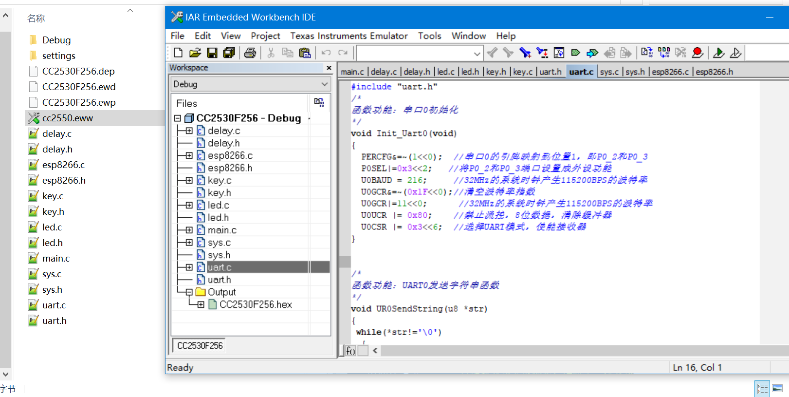
6.1 uart.c
#include "uart.h"
/*
Function function: serial port 0 initialization
*/
void Init_Uart0(void)
{
  PERCFG&=~(1<<0);  //The pin of serial port 0 is mapped to position 1, i.e. P0_2 and P0_ three
  P0SEL|=0x3<<2;   //Set P0_2 and P0_ Port 3 is set as peripheral function
  U0BAUD = 216;     //The 32MHz system clock generates a baud rate of 115200BPS
  U0GCR&=~(0x1F<<0);//Clear baud rate index
  U0GCR|=11<<0;      //The 32MHz system clock generates a baud rate of 115200BPS
  U0UCR |= 0x80;    //Disable flow control, 8-bit data, clear buffer
  U0CSR |= 0x3<<6;  //Select UART mode to enable the receiver
}


/*
Function function: UART0 send string function
*/
void UR0SendString(u8 *str)
{
 while(*str!='\0')
  {
    U0DBUF = *str;    //Write 1-byte data to be sent to U0DBUF
    while(UTX0IF == 0);//Wait for data transmission to complete
    UTX0IF = 0;       //Clear the transmission completion flag and prepare for the next transmission
    str++;
  }
}

/*
Function function: format and print function imitating printf style
*/
char USART0_PRINT_BUFF[200]; //Format data cache data
void USART0_Printf(const char *format,...)
{
  char *str=NULL;
  /*1. Format conversion*/
  va_list ap; // va_list---->char *
  va_start(ap,format); //Initialization parameter list
  vsprintf(USART0_PRINT_BUFF,
        format,
        ap); //formatted print
  va_end(ap); //End parameter acquisition
  /*2. Serial port printing*/
  str=USART0_PRINT_BUFF;//Pointer assignment
  while(*str!='\0')
  {
    U0DBUF=*str; //Send one byte of data
    str++; //The pointer increases automatically and points to the next data
    while(UTX0IF == 0);//Wait for data transmission to complete
    UTX0IF = 0;       //Clear the transmission completion flag and prepare for the next transmission
  }
}
6.2 DHT11.c
#include "dht11.h"
#include "delay.h"


#define DATA_PIN P0_7

//Definition of temperature and humidity
uchar ucharFLAG,uchartemp;
uchar shidu_shi,shidu_ge,wendu_shi,wendu_ge=4;
uchar ucharT_data_H,ucharT_data_L,ucharRH_data_H,ucharRH_data_L,ucharcheckdata;
uchar ucharT_data_H_temp,ucharT_data_L_temp,ucharRH_data_H_temp,ucharRH_data_L_temp,ucharcheckdata_temp;
uchar ucharcomdata;

//Delay Functions
void Delay_us() //1 us delay
{
    asm("nop");
    asm("nop");
    asm("nop");
    asm("nop");
    asm("nop");
    asm("nop");
    asm("nop");
    asm("nop");
    asm("nop");
}

void Delay_10us() //10 us delay
{
  #if 0
  Delay_us();
  Delay_us();
  Delay_us();
  Delay_us();
  Delay_us();
  Delay_us();
  Delay_us();
  Delay_us();
  Delay_us();
  Delay_us();
  #else
    int i = 10;
    while(i--);
#endif
}

void Delay_ms(unsigned int Time)//n ms Delay
{
    unsigned char i;
    while(Time--)
    {
        for(i=0;i<100;i++)
            Delay_10us();
    }
}

//Temperature and humidity sensing
void COM(void)    // Warm wet writing
{
    uchar i;
    for(i=0;i<8;i++)
    {
        ucharFLAG=2;
        while((!DATA_PIN)&&ucharFLAG++);
        Delay_10us();
        Delay_10us();
        Delay_10us();
        uchartemp=0;
        if(DATA_PIN)uchartemp=1;
        ucharFLAG=2;
        while((DATA_PIN)&&ucharFLAG++);
        if(ucharFLAG==1)break;
        ucharcomdata<<=1;
        ucharcomdata|=uchartemp;
    }
}

void DHT11(void)   //Temperature and humidity sensing start
{
    DATA_PIN=0;
    Delay_ms(19);  //>18MS
    DATA_PIN=1;
    P0DIR &= ~0x80; //Reconfigure IO port direction
    Delay_10us();
    Delay_10us();
    Delay_10us();
    Delay_10us();
    if(!DATA_PIN)
    {
        ucharFLAG=2;
        while((!DATA_PIN)&&ucharFLAG++);
        ucharFLAG=2;
        while((DATA_PIN)&&ucharFLAG++);
        COM();
        ucharRH_data_H_temp=ucharcomdata;
        COM();
        ucharRH_data_L_temp=ucharcomdata;
        COM();
        ucharT_data_H_temp=ucharcomdata;
        COM();
        ucharT_data_L_temp=ucharcomdata;
        COM();
        ucharcheckdata_temp=ucharcomdata;
        DATA_PIN=1;
        uchartemp=(ucharT_data_H_temp+ucharT_data_L_temp+ucharRH_data_H_temp+ucharRH_data_L_temp);
        if(uchartemp==ucharcheckdata_temp)
        {
            ucharRH_data_H=ucharRH_data_H_temp;
            ucharRH_data_L=ucharRH_data_L_temp;
            ucharT_data_H=ucharT_data_H_temp;
            ucharT_data_L=ucharT_data_L_temp;
            ucharcheckdata=ucharcheckdata_temp;
        }
        wendu_shi=ucharT_data_H/10;
        wendu_ge=ucharT_data_H%10;

        shidu_shi=ucharRH_data_H/10;
        shidu_ge=ucharRH_data_H%10;
    }
    else //Failed to read successfully, return 0
    {
        wendu_shi=0;
        wendu_ge=0;

        shidu_shi=0;
        shidu_ge=0;
    }

    P0DIR |= 0x80; //The IO port needs to be reconfigured
}
6.3 BH1750.c
#include "bh1750.h"
u8 Read_BH1750_Data()
{
    unsigned char t0;
    unsigned char t1;
    unsigned char t;
    u8 r_s=0;
    IIC_Start(); //Send start signal
    IIC_WriteOneByteData(0x46);
    r_s=IIC_GetACK();//Get response
    if(r_s)USART0_Printf("error:1\r\n");
    IIC_WriteOneByteData(0x01);
    r_s=IIC_GetACK();//Get response
     if(r_s)USART0_Printf("error:2\r\n");
    IIC_Stop(); //Stop signal

    IIC_Start(); //Send start signal
    IIC_WriteOneByteData(0x46);
    r_s=IIC_GetACK();//Get response
    if(r_s)USART0_Printf("error:3\r\n");
    IIC_WriteOneByteData(0x01);
    r_s=IIC_GetACK();//Get response
    if(r_s)USART0_Printf("error:4\r\n");
    IIC_Stop(); //Stop signal

    IIC_Start(); //Send start signal
    IIC_WriteOneByteData(0x46);
    r_s=IIC_GetACK();//Get response
    if(r_s)USART0_Printf("error:5\r\n");
    IIC_WriteOneByteData(0x10);
    r_s=IIC_GetACK();//Get response
    if(r_s)USART0_Printf("error:6\r\n");
    IIC_Stop(); //Stop signal

    DelayMs(300); //wait for

    IIC_Start(); //Send start signal
    IIC_WriteOneByteData(0x47);
    r_s=IIC_GetACK();//Get response
    if(r_s)USART0_Printf("error:7\r\n");

    t0=IIC_ReadOneByteData(); //receive data
    IIC_SendACK(0); //Send response signal
    t1=IIC_ReadOneByteData(); //receive data
    IIC_SendACK(1); //Send non reply signal
    IIC_Stop(); //Stop signal

     t=(((t0<<8)|t1)/1.2);
     return t;
}
5, Build IAR environment -- build CC2530 development environment