catalogue
3. Overview of single arm routing
2, Three layer switching technology
1. Three layer switching principle
3. Configuration of layer 3 switch
1, Single arm routing
The physical interface of the router can be divided into multiple logical sub interfaces, and each sub interface corresponds to the gateway of a vlan network segment
Single arm Routing: realize communication between different LAN s
Principle:
The router reseals the MAC address and converts the Vlan label
1. Link type
1) The port connecting the switch to the host is the access link
2) The port connecting the switch to the router is the Trunk link
2. Sub interface
1) The physical interface of the router can be divided into multiple logical interfaces
2) Each sub interface corresponds to the gateway of a VLAN segment
3. Overview of single arm routing
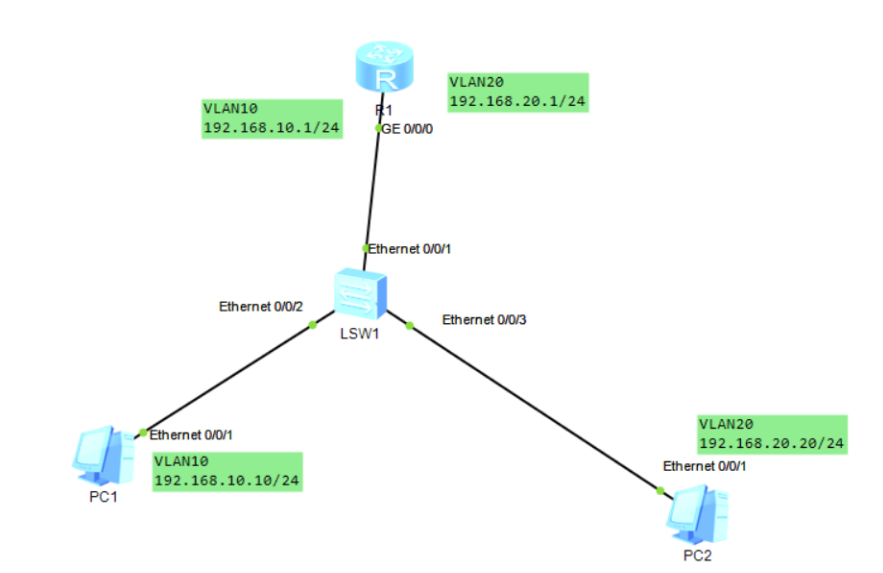
A. Communication between hosts a and B: host a and B encapsulate their IP and MAC through the ACCESS interface, affix labels and send them to the switch. The F0/24 of the switch checks the labels, and then sends them to the router (F0/0 sub interface), unpack them, tear off the labels (VLAN10), then reseal them, pass through F0/24, affix the labels of VLAN20 again, and send them to host B through F0/2 (tear off the labels).
4. Configuration command
1) Switch configuration
#Switch configuration
<Huawei>undo t m
[SW1]vlan batch 10 20
[SW1]int e0/0/1
[SW1-Ethernet0/0/1]port link-type access
[Sw1-Ethernet0/0/1]port default vlan 10
[Sw1-Etherneto/0/1]undo sh Info:Interface Etherneto/0/1 is not shutdown.
[sw1-Ethernet0/0/1]int e0/0/2
[Sw1-Ethernet0/0/2]port link-type access
[Sw1-Ethernet0/0/2]port default vlan 20
[Sw1-Etherneto/0/2]undo sh
[sw1-Etherneto/0/2]int e0/0/3
[sw1-Ethernet0/0/3]port link-type trunk
[SW1-Ethernet0/0/3]port trunk allow-pass vlan all
[SW1-Etherneto/0/3]undo shutdown
2) Router configuration
#Router configuration
[R1]int g0/0/0.10I
#0-4095
[R1-GigabitEthernet0/0/0.10]dotlq termination vid 10
[R1-GigabitEthernet0/0/0.10]ip add 192.168.10.1 24
[R1-GigabitEtherneto/0/0.10]arp broadcast enable
#Be sure to turn it on
[R1-GigabitEthernet0/0/0.10]undo sh
[R1]int go/0/0.20
[R1-GigabitEthernetO/0/0.20]dot1q termination vid 20
[R1-GigabitEthernet0/0/0.20]ip add 192.168.20.1 24
[R1-GigabitEthernet0/0/0.20]undo sh
[R1-GigabitEthernet0/0/0.20]arp broadcast enable
#Be sure to turn it on
<Rl>display interface brief
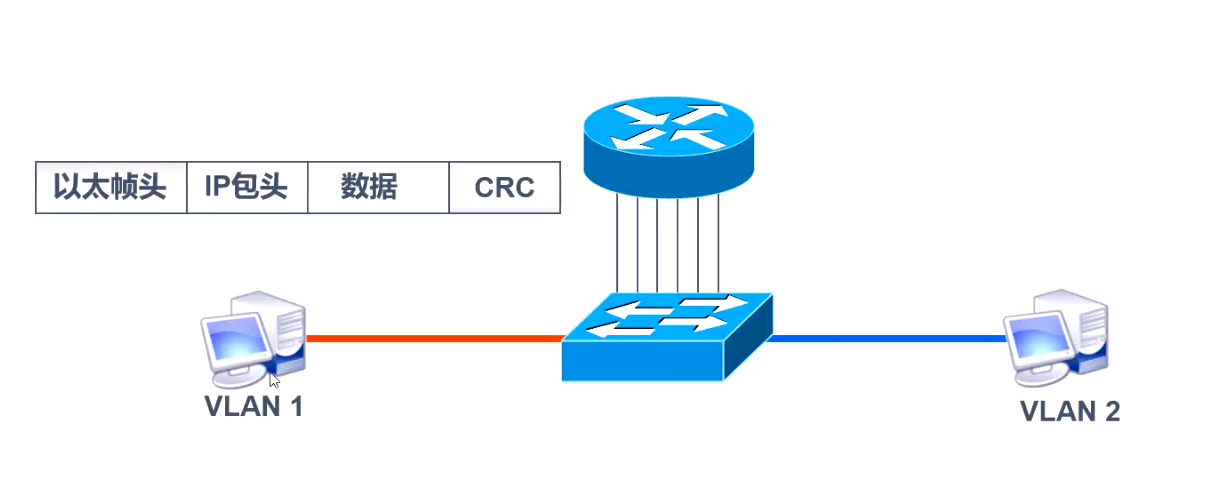
2, Three layer switching technology
1. Three layer switching principle
Layer 3 switching technology can realize communication between VLAN s
Layer 3 switching = layer 2 switching + layer 3 forwarding
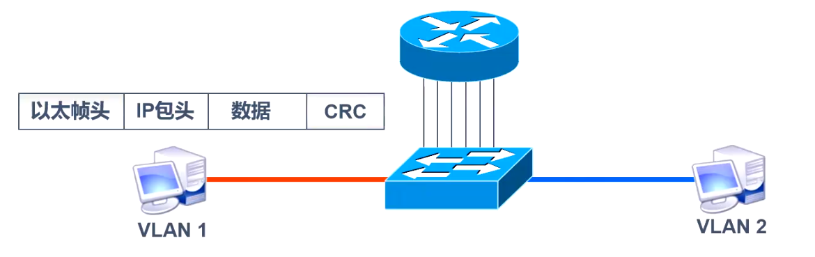
When the layer 3 device receives a data frame, it will remove the original data frame and reseal the new source MAC address and target MAC address. Because the information in the frame header changes, the last frame check CRC should also change.
Among the multiple data packets in this stream, only the first data packet is processed by the layer 3 engine of the layer 3 switch in the software mode, which is the same as that of the router. After the layer 3 engine obtains the new layer 2 encapsulation information, it routes the data packet.
After the first packet forwarding is completed, an MLS entry is created in the hardware for the re encapsulation and fast forwarding of subsequent packets by the hardware. The layer 2 data frame will be re encapsulated into the frame format of the next network segment to be forwarded.
This is the principle of "one route, many exchanges" of MLS.
2. CEF based MLS
The key of MLS based on CEF (a topology based forwarding model) is two forwarding information tables. The forwarding information base (FIB) corresponds to the routing table, which is a mirror image of the routing table. When the routing table is updated, the FlB changes accordingly, and the FIB contains the corresponding relationship between the IP address of the adjacent host and the VLANID. The adjacency table contains the corresponding relationship between the MAC addresses of adjacent hosts and switches, which is used to provide layer-2 rewriting information.
The MLS forwarding process based on CEF is to send unicast packets, re encapsulate data frames by looking up FIB and adjacency table, and forward them from the corresponding port.
3. Configuration of layer 3 switch
Enable alternate routing on layer 3 switches
Switch(config)# ip routing
Configure the IP address of the virtual interface
Switch(config)# interface vlan vlan-id
Switch(config-if)# ip address ip address netmask
Switch(config-if)# no shutdown
Configure routing interface
SW1(config)#interface f0/24
SW1(config-if)#switchport trunk allowed vlan remove 2