We enhance realism by wrapping 2D textures on these planar triangles, hiding the fact that polygons are only small planar triangles.
From the perspective of lighting technology, the only way to determine the shape of an object is through its vertical normal vector.
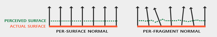
This technique that uses per segment normals compared to per surface normals is called normal mapping or bump mapping. Applied to brick planes, it looks a bit like this:
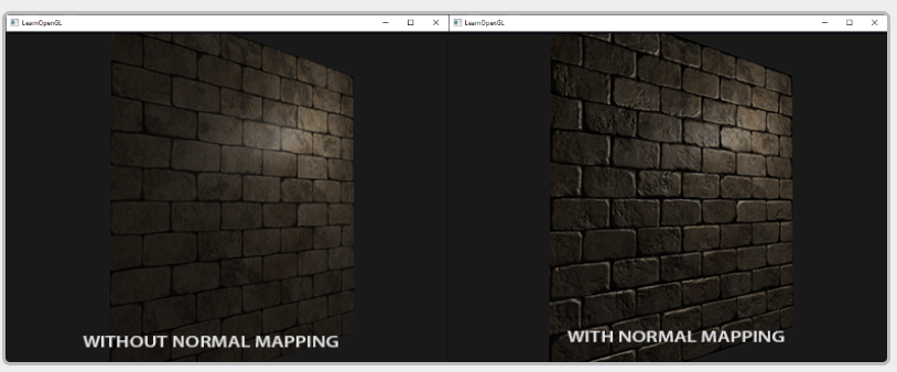 As you can see, it provides a huge improvement in detail at a relatively low cost. Since we only change the normal vector of each clip, there is no need to change the lighting equation.
Basics:
1.Normal mapping
Although the normal vector is a geometric entity, the texture is usually only used for color information, and the color vector is represented as a 3D vector with r, g and b components. We can similarly store the x, y, and z components of the normal vector in the corresponding color components. Normal vectors range between - 1 and 1, so they first map to [0,1]:
vec3 rgb_normal = normal * 0.5 + 0.5; // transforms from [-1,1] to [0,1]
By converting the normal vector to such an RGB color component, we can store each fragment normal from the surface shape on the 2D texture.
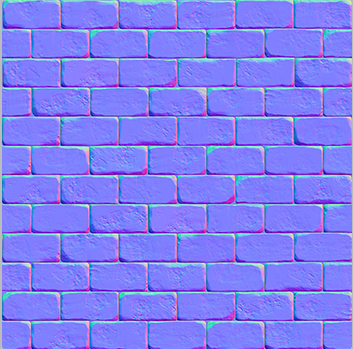
This (and almost all normal maps you find online) will have a blue tone. This is because the normals are pointing closely outward towards the positive z axis (0,0,1): a bluish color. The color deviation indicates that the normal vector is slightly offset from the general positive z direction, so as to provide a sense of depth for the texture. For example, you can see that at the top of each brick, the normal color facing up and down tends to be more green, which makes sense, because the normal at the top of the brick will point more in the positive y direction (0,1,0), which will become green!
Load two textures, bind them to the appropriate texture unit, and change the render plane in the photo segment shader using the following:
uniform sampler2D normalMap;
void main()
{
// obtain normal from normal map in range [0,1]
normal = texture(normalMap, fs_in.TexCoords).rgb;
// transform normal vector to range [-1,1]
normal = normalize(normal * 2.0 - 1.0);
[...]
// proceed with lighting as normal
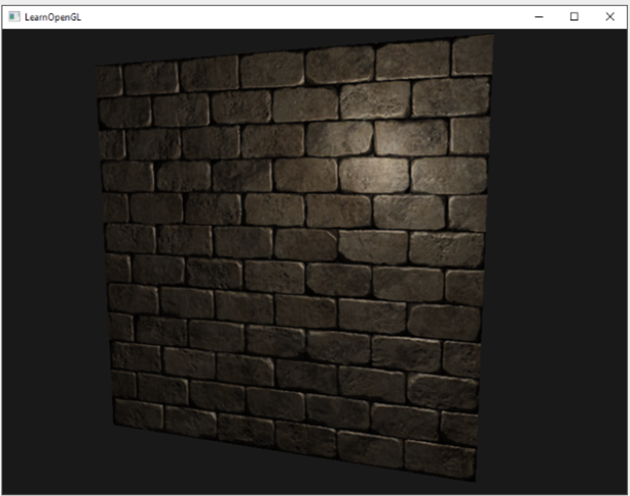
} By moving the light source slowly over time, you can use the normal map to really get a sense of depth. Running this normal map example gives the exact results shown at the beginning of this chapter:
The normal map we use has normal vectors, which all point in a fixed direction. However, if we change the angle of the map and use this normal vector, it will also point to the fixed direction, resulting in problems with the normal map.
There is a solution that the normal map vector always points to the coordinate space in the positive z direction; Then all other light vectors are converted relative to this positive z direction. In this way, we can always use the same normal map, regardless of direction. This coordinate space is called tangent space.
2.Tangent space
The normal map is defined in tangent space. One way to solve the problem is to calculate a matrix, convert the normals from tangent space to different spaces, and align them with the normal direction of the surface: then the normal vectors point roughly in the positive y direction. The great thing about tangent space is that we can calculate this matrix for any type of surface so that we can correctly align the z direction of tangent space with the normal direction of the surface.
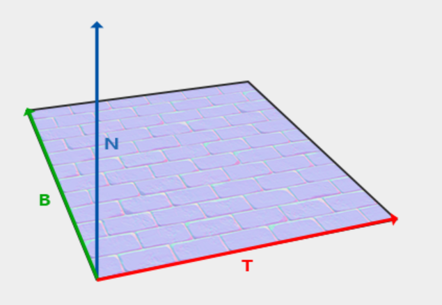
Such a matrix is called TBN (Tangent, Bitangent and Normal vector.) Matrix, where letters represent Tangent, Bitangent, and Normal vectors. These are the vectors we need to build this matrix. In order to construct such a change basis matrix and convert Tangent space vectors to different coordinate spaces, we need three vertical vectors aligned along the Normal map surface: up, right and forward vectors;
We already know that the up vector is the normal vector of the surface. The right vector and the front vector are tangent and bitangent vector bitangent vectors, respectively.
Calculating tangent and bitangent vectors is not as simple as normal vectors. From the image, we can see that the direction of tangent and bitangent vector of normal map is aligned with the direction we define the surface texture coordinates. We will use this fact to calculate the tangent and bitangent vectors for each surface.
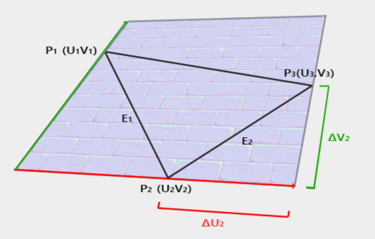
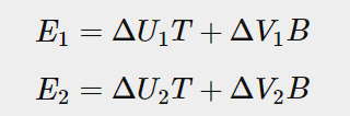
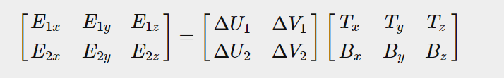
From the figure, we can see the texture coordinate difference of edge E2 of the triangle (recorded as Δ U2 and Δ V2) is represented in the same direction as tangent vector T and double tangent vector B. Therefore, we can write E1 and E2 of two displayed edge triangles as a linear combination of tangent vector T and double tangent vector B:
T: tangent vector
B: bitangent vector
DV: vertical component of triangle edge E
DU: transverse component of triangle edge E
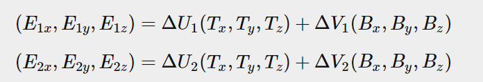
It can also be written as: disassemble each letter X into (X1x,X2x,X3x)
We can treat E1 and E2 as two edge vectors of a triangle Δ U and Δ V is calculated as their texture coordinate difference. Then we leave two unknowns (tangent T and bitangent b) and two equations. As you may recall from the algebra lesson, this enables us to solve t and B.
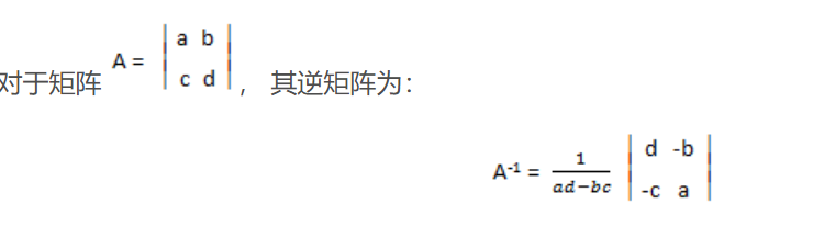
The last equation allows us to write in different forms: matrix multiplication:
Switch:
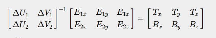
Switch again:
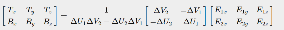
The last equation provides us with a formula to calculate the tangent vector T and double tangent vector B according to the two sides of the triangle and their texture coordinates.
We can calculate tangents and bitangents from the vertices of the triangle and its texture coordinates (because the texture coordinates are in the same space as the tangent vector).
3.Manual calculation of tangents and bitangents
Let's assume that the plane is composed of the following vectors (pos1, pos2,pos3 and pos1, pos3, pos4 as its two triangles):
// positions
glm::vec3 pos1(-1.0,  1.0, 0.0);
glm::vec3 pos2(-1.0, -1.0, 0.0);
glm::vec3 pos3( 1.0, -1.0, 0.0);
glm::vec3 pos4( 1.0,  1.0, 0.0);
// texture coordinates
glm::vec2 uv1(0.0, 1.0);
glm::vec2 uv2(0.0, 0.0);
glm::vec2 uv3(1.0, 0.0);
glm::vec2 uv4(1.0, 1.0);
// normal vector
glm::vec3 nm(0.0, 0.0, 1.0);
We first calculate the edge and delta UV coordinates of the first triangle:
glm::vec3 edge1 = pos2 - pos1;
glm::vec3 edge2 = pos3 - pos1;
glm::vec2 deltaUV1 = uv2 - uv1;
glm::vec2 deltaUV2 = uv3 - uv1;
With the data needed to calculate tangents and sub tangents, we can begin to follow the equation in the previous section:
float f = 1.0f / (deltaUV1.x * deltaUV2.y - deltaUV2.x * deltaUV1.y);

tangent1.x = f * (deltaUV2.y * edge1.x - deltaUV1.y * edge2.x);
tangent1.y = f * (deltaUV2.y * edge1.y - deltaUV1.y * edge2.y);
tangent1.z = f * (deltaUV2.y * edge1.z - deltaUV1.y * edge2.z);

bitangent1.x = f * (-deltaUV2.x * edge1.x + deltaUV1.x * edge2.x);
bitangent1.y = f * (-deltaUV2.x * edge1.y + deltaUV1.x * edge2.y);
bitangent1.z = f * (-deltaUV2.x * edge1.z + deltaUV1.x * edge2.z);

[...] // similar procedure for calculating tangent/bitangent for plane's second triangle
Visualize on a plane, the TBN vector will be as follows: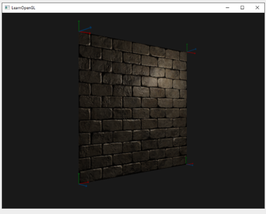
By defining tangent and bitangent vectors for each vertex, we can begin to achieve the correct normal mapping.
4. Tangent space normal mapping
In order for normal mapping to work, we must first create a TBN (tangent and bitangent and normal) matrix in the shader. To do this, we pass the previously calculated tangent and bitangent vectors to the vertex shader as vertex attributes:
#version 330 core
layout (location = 0) in vec3 aPos;
layout (location = 1) in vec3 aNormal;
layout (location = 2) in vec2 aTexCoords;
layout (location = 3) in vec3 aTangent;
layout (location = 4) in vec3 aBitangent;
Create TBN matrix:
void main()
{
   [...]
   vec3 T = normalize(vec3(model * vec4(aTangent,   0.0)));
   vec3 B = normalize(vec3(model * vec4(aBitangent, 0.0)));
   vec3 N = normalize(vec3(model * vec4(aNormal,    0.0)));
   mat3 TBN = mat3(T, B, N);
}
We create the actual TBN matrix by directly providing the relevant column vector for the constructor of mat3. Note that if we want to be really accurate, we will multiply the TBN vector by the normal matrix, because we only care about the direction of the vector.
Technically, bitangent variables are not required in vertex shaders. All three TBN vectors are perpendicular to each other, so we can calculate the double tangent by ourselves in the vertex shader through the cross product of T and N vectors: vec3 B = cross(N, T);
There are two methods for normal mapping using TBN matrix (vector with normal coordinate system in it):
1. For any vector, we convert TBN matrix from tangent coordinate system to world space coordinate system, provide it to fragment shader, and convert the normals sampled by TBN matrix from tangent space to world space; Then the normal is in the same space as the other lighting variables.
2. We convert any vector from world space to tangent space through the inverse matrix of TBN matrix, and use this matrix to convert other relevant lighting variables to tangent space instead of normal; Then the normal is again in the same space as the other lighting variables.
By passing the TBN matrix to the clip shader, we can multiply the sampled tangent space normal by the TBN matrix to convert the normal vector into the same reference space as other illumination vectors.
Summary: three ts points can render a region and countless fs points. In the second kind, the data in tangent space is directly used for calculation in fs, which saves a lot of matrix operation and countless fs points. Specific how to omit, you can see the following fs code
Send TBN matrix to fs:
vs:
out VS_OUT {
    vec3 FragPos;
    vec2 TexCoords;
    mat3 TBN;
} vs_out;

void main()
{
    [...]
    vs_out.TBN = mat3(T, B, N);
}
fs:
in VS_OUT {
    vec3 FragPos;
    vec2 TexCoords;
    mat3 TBN;
} fs_in;
With this TBN matrix, we can now update the normal mapping code to include the transformation from tangent to world space:
normal = texture(normalMap, fs_in.TexCoords).rgb;
normal = normal * 2.0 - 1.0;
normal = normalize(fs_in.TBN * normal);
Since the generated normals are now in world space, there is no need to change any other clip shader code because the illumination code assumes that the normal vector is in world space.
The second case:
Let's review the second case. We take the inverse matrix of TBN matrix and transform all relevant world space vectors to the space where the sampling normal vector is located: tangent space. The construction of the TBN matrix remains unchanged, but we invert the matrix before sending it to the clip shader:
vs_out.TBN = transpose(mat3(T, B, N));
Note that we use transpose functions instead of inverse functions here. An important characteristic of orthogonal matrix (each axis is a vertical unit vector) is that the transpose of orthogonal matrix is equal to its inverse matrix. This is a good property because inverse is expensive and transpose is not.
In the fragment shader, we do not convert normal vectors, but we convert other related vectors to tangent space, namely lightDir and viewDir vectors. In this way, each vector is in the same coordinate space: tangent space.
vs:
void main()
{
    vec3 normal = texture(normalMap, fs_in.TexCoords).rgb;
    normal = normalize(normal * 2.0 - 1.0);

    vec3 lightDir = fs_in.TBN * normalize(lightPos - fs_in.FragPos);
    vec3 viewDir  = fs_in.TBN * normalize(viewPos - fs_in.FragPos);
    [...]
}
The second method seems to be more demanding and requires matrix multiplication in the fragment shader, so why bother with the second method?
Well, converting vectors from world space to tangent space has an additional advantage because we can convert all relevant lighting vectors to tangent space in vertex shaders instead of fragment shaders. This is valid because lightPos and viewPos do not run on each fragment shader, for fs_in.FragPos we can calculate its tangent space position in the vertex shader and let the clip difference do its work. In fact, there is no need to convert the vector to the tangent space required in the clip shader, while the first method is necessary because the sampled normal vector is specific to each clip shader run.
Therefore, instead of sending the inverse of the TBN matrix to the clip shader, we send the tangent space light position, view position and vertex position to the clip shader. This eliminates the need for matrix multiplication in fragment shaders. This is a good optimization because vertex shaders run much less frequently than fragment shaders. This is why this method is usually the preferred method.
Summary: in the first, the tangent TBN vector transmitted from vs to FS is different every time. It is possible that one vs point can be repeatedly calculated for 10 times, and the value of FS is different every time. In the second, one vs point can be transmitted to 10 fs with the same number, so it is not necessary to calculate every time?
vs:
out VS_OUT {
    vec3 FragPos;
    vec2 TexCoords;
    vec3 TangentLightPos;
    vec3 TangentViewPos;
    vec3 TangentFragPos;
} vs_out;

uniform vec3 lightPos;
uniform vec3 viewPos;

[...]

void main()
{
    [...]
    //By inverting TBN, the point can be converted from the world coordinate system to the normal coordinate system
    mat3 TBN = transpose(mat3(T, B, N));
    vs_out.TangentLightPos = TBN * lightPos;
    vs_out.TangentViewPos  = TBN * viewPos;
    vs_out.TangentFragPos  = TBN * vec3(model * vec4(aPos, 1.0));
}
In the clip shader, we then use these new input variables to calculate the illumination in tangent space. Since the normal vector is already in tangent space, illumination makes sense.
fs:
#version 330 core
out vec4 FragColor;

in VS_OUT {
    vec3 FragPos;
    vec2 TexCoords;
    vec3 TangentLightPos;
    vec3 TangentViewPos;
    vec3 TangentFragPos;
} fs_in;

uniform sampler2D diffuseMap;
uniform sampler2D normalMap;

uniform vec3 lightPos;
uniform vec3 viewPos;

void main()
{
     // obtain normal from normal map in range [0,1]
    vec3 normal = texture(normalMap, fs_in.TexCoords).rgb;
    // transform normal vector to range [-1,1]
    normal = normalize(normal * 2.0 - 1.0);  // this normal is in tangent space

    // get diffuse color
    vec3 color = texture(diffuseMap, fs_in.TexCoords).rgb;
    // ambient
    vec3 ambient = 0.1 * color;
    // The calculation here is directly calculated with the normal coordinate system, because the difference between the normal coordinate system and the real coordinate system is the same
    vec3 lightDir = normalize(fs_in.TangentLightPos - fs_in.TangentFragPos);
    float diff = max(dot(lightDir, normal), 0.0);
    vec3 diffuse = diff * color;
    // specular
    vec3 viewDir = normalize(fs_in.TangentViewPos - fs_in.TangentFragPos);
    vec3 reflectDir = reflect(-lightDir, normal);
    vec3 halfwayDir = normalize(lightDir + viewDir);
    float spec = pow(max(dot(normal, halfwayDir), 0.0), 32.0);

    vec3 specular = vec3(0.2) * spec;
    FragColor = vec4(ambient + diffuse + specular, 1.0);
}
5.Complex objects
Assimp has a very useful configuration bit, and we can load it called aiProcess_CalcTangentSpace is set when the model is. When aiprocess_ When the calctangentspace bit is supplied to assimp's ReadFile function, assimp calculates smooth tangent and bitangent vectors for each loaded vertex, similar to what we did in this chapter.
const aiScene *scene = importer.ReadFile(
    path, aiProcess_Triangulate | aiProcess_FlipUVs | aiProcess_CalcTangentSpace
);
In Assimp, we can retrieve the calculated tangent in the following ways:
vector.x = mesh->mTangents[i].x;
vector.y = mesh->mTangents[i].y;
vector.z = mesh->mTangents[i].z;
vertex.Tangent = vector;
vector<Texture> normalMaps = loadMaterialTextures(material, aiTextureType_HEIGHT, "texture_normal");
Using normal mapping, we can get the same level of detail on the mesh with fewer vertices. The following image from Paolo Cignoni shows a good comparison of the two methods:
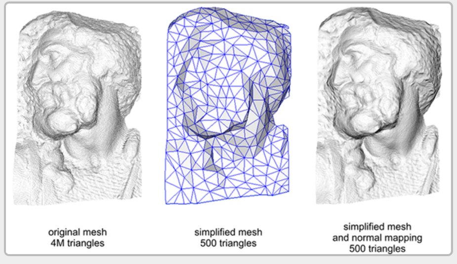
It is a good tool to replace high vertex meshes with low vertex meshes without losing (too much) detail.
When calculating tangent vectors on larger meshes that share a large number of vertices, tangent vectors are usually averaged to provide good and smooth results. One problem with this method is that the three TBN vectors may not be vertical in the end, which means that the final TBN matrix will no longer be orthogonal. When using non orthogonal TBN matrix, the normal map will only deviate slightly, but this is still something we can improve.
Using a mathematical technique called gram Schmidt process, we can re orthogonalize TBN vectors so that each vector is perpendicular to other vectors again. In the vertex shader, we do this:
vec3 T = normalize(vec3(model * vec4(aTangent, 0.0)));
vec3 N = normalize(vec3(model * vec4(aNormal, 0.0)));
// re-orthogonalize T with respect to N
T = normalize(T - dot(T, N) * N);
// then retrieve perpendicular vector B with the cross product of T and N
vec3 B = cross(N, T);

mat3 TBN = mat3(T, B, N)
This is a slight improvement, but it usually improves normal mapping results at a little extra cost.