Learning content of the third week
stm32 clock system
Hardware
- STM32 has five clock sources: HSI, HSE, LSI, LSE and PLL.
① HSI is a high-speed internal clock and RC oscillator. The frequency is 8MHz and the accuracy is not high.
② HSE is a high-speed external clock, which can be connected to quartz / ceramic resonator or external clock
Clock source, frequency range 4MHz~16MHz.
③ LSI is a low-speed internal clock and RC oscillator with a frequency of 40kHz, providing a low-power clock. WDG
④ LSE is a low-speed external clock connected with quartz crystal with a frequency of 32.768kHz. RTC
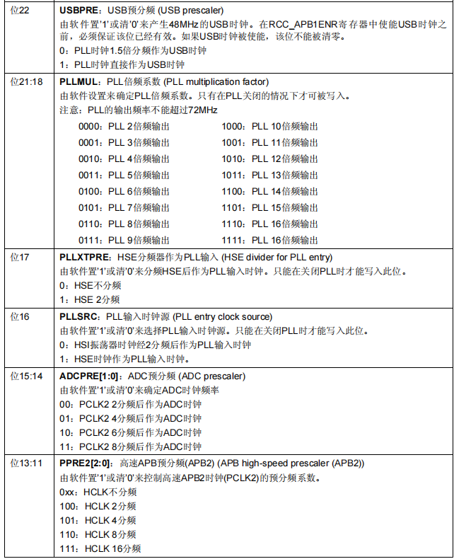
⑤ / HSE PLL or HSE 2 / PLL input can be selected.
The frequency doubling can be 2 ~ 16 times, but the maximum output frequency shall not exceed 72MHz. - The system clock SYSCLK can come from three clock sources:
① HSI oscillator clock
② HSE oscillator clock
③ PLL clock
3.STM32 can select a clock signal to output to MCO pin (PA8) and PLL
Output 2 frequency division, HSI, HSE, or system clock.
4. Any peripheral must enable its corresponding clock before use.
Function setting example
If you define a frequency, execute the corresponding function
static void SetSysClock(void)
{
#ifdef SYSCLK_FREQ_HSE
  SetSysClockToHSE();
#elif defined SYSCLK_FREQ_24MHz
  SetSysClockTo24();
#elif defined SYSCLK_FREQ_36MHz
  SetSysClockTo36();
#elif defined SYSCLK_FREQ_48MHz
  SetSysClockTo48();
#elif defined SYSCLK_FREQ_56MHz
  SetSysClockTo56();
#elif defined SYSCLK_FREQ_72MHz
  SetSysClockTo72();
#endif
If it is set to 72 MHz, call SetSysClockTo72();
This function is
static void SetSysClockTo72(void)
{
  __IO uint32_t StartUpCounter = 0, HSEStatus = 0;

  /* SYSCLK, HCLK, PCLK2 and PCLK1 configuration ---------------------------*/
  /* Enable HSE */
  RCC->CR |= ((uint32_t)RCC_CR_HSEON);//Enable HSE clock

  /* Wait till HSE is ready and if Time out is reached exit */
  do
  {
    HSEStatus = RCC->CR & RCC_CR_HSERDY;
    StartUpCounter++;
  } while((HSEStatus == 0) && (StartUpCounter != HSE_STARTUP_TIMEOUT));
Judge whether the clock is started and completed

  if ((RCC->CR & RCC_CR_HSERDY) != RESET)
  {
    HSEStatus = (uint32_t)0x01;
  }
  else
  {
    HSEStatus = (uint32_t)0x00;
  }

  if (HSEStatus == (uint32_t)0x01)After startup, execute the following functions
  {
    /* Enable Prefetch Buffer */
    FLASH->ACR |= FLASH_ACR_PRFTBE;

    /* Flash 2 wait state */
    FLASH->ACR &= (uint32_t)((uint32_t)~FLASH_ACR_LATENCY);
    FLASH->ACR |= (uint32_t)FLASH_ACR_LATENCY_2;


    /* HCLK = SYSCLK */72mhz
    RCC->CFGR |= (uint32_t)RCC_CFGR_HPRE_DIV1;

    /* PCLK2 = HCLK */72mhz
    RCC->CFGR |= (uint32_t)RCC_CFGR_PPRE2_DIV1;

    /* PCLK1 = HCLK /2*/ 36mhz
RCC->CFGR |= (uint32_t)RCC_CFGR_PPRE1_DIV2;
These three lines set the frequency division coefficient of the clock
For detailed configuration parameters, refer to stm32 reference manual 6.3.2 clock configuration register rcc_cfgr
Delay function
The maximum delay MS can be calculated by the formula: nms < = 0xffff81000 / SYSCLK. SYSCLK is in Hz and nms is in MS. If the clock is 72M, the maximum value of nms is 1864ms. If this value is exceeded, it is recommended to call delay multiple times_ MS implementation, otherwise it will lead to inaccurate delay.
Systick timer
Systick timer is often used to delay or heartbeat clock of real-time system. This can save MCU resources without wasting a timer. For example, in UCOS, time-sharing multiplexing requires a minimum timestamp. Generally, systick is used as UCOS heartbeat clock in STM32+UCOS system.
SysTick timer is the system tick timer, a 24 bit countdown timer. When it counts to 0, it will automatically RELOAD the initial value of timing from the RELOAD register. As long as its enable bit in SysTick control and status register is not cleared, it will never stop and can work even in sleep mode.
Systick timer is bundled in NVIC to generate systick exception (exception No.: 15).
The priority of Systick interrupt can also be set.
UCOSII clock
The operation of ucos requires a system clock beat (similar to "heartbeat"), which is fixed (OS_TICKS_PER_SEC macro definition setting). For example, it requires 5ms once (that is, OS_TICKS_PER_SEC=200). On STM32, SysTick generally provides this beat, that is, SysTick should be set to interrupt once in 5ms to provide a clock beat for ucos, And this clock can't be interrupted (otherwise it's not allowed).
#ifdef CPU_CFG_CRITICAL_METHOD / / use UCOSIII
OS_ERR err;
OSSchedUnlock(&err); //UCOSIII mode, resume scheduling
#else / / otherwise, UCOSII
OSSchedUnlock(); //UCOSII mode, resume scheduling
#endif
}
//Call the delay function of the OS
//ticks: delayed beats
void delay_ostimedly(u32 ticks)
{
#ifdef CPU_CFG_CRITICAL_METHOD / / when using UCOSIII
OS_ERR err;
OSTimeDly(ticks,OS_OPT_TIME_PERIODIC,&err);//Ucosiiii delay adopts periodic mode
#else
OSTimeDly(ticks); //UCOSII delay
#endif
}
//systick interrupt service function, used when using ucos
void SysTick_Handler(void)
{
if(delay_osrunning==1) //When the OS starts running, the normal scheduling processing is executed
{
OSIntEnter(); //Entry interrupt
OSTimeTick(); //Call ucos clock service program
OSIntExit(); //Trigger task switching soft interrupt
} }
The above codes are only supported UCOSII and UCOSIII,However, for other OS of
SysTick_CLKSourceConfig(SysTick_CLKSource_HCLK_Div8)
In this sentence, the SysTick clock is selected as the external clock. It should be noted here that: the SysTick clock originates from the 8-division frequency of HCLK. Assuming that our external crystal oscillator is 8M and then frequency doubled to 72M, the SysTick clock is 9Mhz, that is, every time SysTick counter VAL decreases by 1, it means that the time has passed 1/9us. So fac_us=SystemCoreClock/8000000; This sentence is to calculate how many SysTick clock cycles are required to delay 1us at the systemcorelock clock frequency. Similarly, fac_ms=(u16)fac_us*1000; It is to calculate the number of SysTick clock cycles required for a delay of 1ms, which is naturally 1000 times that of 1us. Initialization will calculate fac_us and fac_ The value of MS.
fac_us is 8-bit shaping data, fac_ms is 16 bit shaping data.
When not using OS: fac_us is the cardinality of us delay, that is, the value that systick - > load should set when the delay is 1us. fac_ MS is the base of MS delay, that is, the value that systick - > load should set when the delay is 1ms. fac_us is 8-bit shaping data, fac_ MS is 16 bit shaping data. Systick's clock is divided by 8 of the system clock. Because of this, if the system clock is not a multiple of 8 (cannot be divided by 8), the delay function will be inaccurate, which is why we recommend 8M as the external clock. We should pay special attention to this. When using OS, fac_us is also the base of us delay, but this value will not be written to systick - > load register to realize the delay, but through the method of clock extraction (introduced earlier). And fac_ MS represents the minimum delay time that ucos can achieve by its own delay function (for example, delay_ostickspersec=200, then fac_ms is 5ms).
Clock extraction method
When OS is adopted, SysTick timer (24 bits, counting down) is used as the system clock of OS. SysTick timer cannot be modified. If you want to use SysTick timer to realize accurate delay, you can only read the count value in SysTick timer:
For example: delayUs(100) delay 100us;
1. When entering the delayUs function, calculate the SysTick count value required to reach the delay of 100US; For example, the current SysTick count value is 2000100us, and the SysTick count value after delay is 2000 + 100108 = 12800; For example, the SysTick counting clock is 108MHz, and the time of one clock is 1/108000000s, that is, the counting times required for 1/108000ms, 1/108us, 1us is 108, and the counting times required for 1ms is 108000; 100us=108100 times;
2. Read the count value of SysTick timer in the delayUs function. When the count value is greater than 12800, the delay time is up and the cycle is exited;
Note: this method is not suitable for long time delay; When exceeding the maximum count value of SysTick timer, the count value before overflow and the count value after overflow of the filter counter shall be considered;
delay_ms function
//Delay nms
//Note the range of nms
//Systick - > load is a 24 bit register, so the maximum delay is:
//nms<=0xffffff*8*1000/SYSCLK
//SYSCLK is in Hz and NMS is in ms
//For 72M, NMS < = 1864
void delay_ms(u16 nms)
{
u32 temp;
SysTick->LOAD=(u32)nms*fac_ms;//Time loading (systick - > load is 24bit)
SysTick->VAL =0x00; //Clear counter
SysTick->CTRL|=SysTick_CTRL_ENABLE_Msk ; //Start counting down
do
{
temp=SysTick->CTRL;
}while((temp&0x01)&&!(temp&(1<<16)));//Waiting time arrives
SysTick->CTRL&=~SysTick_CTRL_ENABLE_Msk; //Turn off counter
SysTick->VAL =0X00; //Clear counter
}
The number of MS delay cannot be too long. Otherwise, if it exceeds the range of LOAD, the high bit will be rounded off, resulting in inaccurate delay. The maximum delay MS can be calculated by the formula: nms < = 0xffff81000 / SYSCLK. SYSCLK is in Hz and nms is in MS. If the clock is 72M, the maximum value of nms is 1864ms. If this value is exceeded, it is recommended to call delay multiple times_ MS implementation, otherwise it will lead to inaccurate delay.
Port multiplexing
- Port multiplexing: if a GPIO can be reused as a function pin of a built-in peripheral, it is called port multiplexing when the GPIO is used as a built-in peripheral. STM32 has many built-in peripherals, and these pins are multiplexed with GPIO. In other words, if a GPIO can be reused as the function pin of the built-in peripheral, when the GPIO is used as the built-in peripheral, it is called multiplexing. For example, as we all know, MCU has serial ports, and STM32 has several serial ports. For example, STM32F103ZET6 has five serial ports. We can check the manual to know that the corresponding IO of the pin of serial port 1 is PA9 and PA10 The default function of PA9 and PA10 is GPIO, so when PA9 and PA10 pins are used as serial port pins and TX and Rx pins of serial port 1, that is port multiplexing.
Here, two ports, PA9 and PA10, are used as examples
There are several steps for multiplexing port initialization:
1) GPIO port clock enable. To use port multiplexing, of course, it is necessary to enable the clock of the port.
RCC_APB2PeriphClockCmd(RCC_APB2Periph_GPIOA, ENABLE)
2) Multiplexed peripheral clock enable. For example, you need to multiplex ports PA9 and PA10 into serial ports, so you need to enable the serial port clock.
RCC_APB2PeriphClockCmd(RCC_APB2Periph_USART1, ENABLE);
3) Port mode configuration. When the peripheral function pin is built in the IO multiplexing bit, the GPIO port mode must be set. How does the GPIO mode correspond to under the multiplexing function
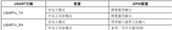
To configure full duplex serial port 1, the TX pin needs to be configured as push-pull multiplex output, and the RX pin needs to be configured as floating input or with pull-up input.
//USART1_TX PA.9 multiplex push-pull output
GPIO_InitStructure.GPIO_Pin = GPIO_Pin_9; //PA.9
GPIO_InitStructure.GPIO_Speed = GPIO_Speed_50MHz;
GPIO_InitStructure.GPIO_Mode = GPIO_Mode_AF_PP; //Multiplex push-pull output
GPIO_Init(GPIOA, &GPIO_InitStructure);
//USART1_RX
PA.10 floating input
GPIO_InitStructure.GPIO_Pin = GPIO_Pin_10;//PA10
GPIO_InitStructure.GPIO_Mode = GPIO_Mode_IN_FLOATING;//Floating input
GPIO_Init(GPIOA, &GPIO_InitStructure);
STM32 NVIC interrupt management
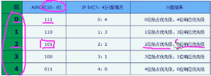
The CM3 kernel supports 256 interrupts, including 16 kernel interrupts and 240 external interrupts, and has 256 levels of programmable interrupt settings. However, STM32 does not use all things of CM3 kernel, but only a part of it. STM32 has 84 interrupts, including 16 kernel interrupts and 68 maskable interrupts, with 16 levels of programmable interrupt priority. We often use these 68 maskable interrupts, but the 68 maskable interrupts of STM32 are only 60 in STM32F103 series (68 in 107 Series). Because the chip selected by our development board is STM32F103 series, we only introduce the 60 maskable interrupts of STM32F103 series.
seize,
It refers to the attribute of interrupting other interrupts, that is, nested interrupts will occur because of this attribute (interrupted by interrupt B during the execution of interrupt service function A, and then continue to execute interrupt service function A after executing interrupt service function B). The preemption attribute is determined by NVIC_ Parameter configuration of irqchannelpreemptionpriority
response
Attribute is applied when the preemption attribute is the same. When the preemption priority of two interrupt vectors is the same, if two interrupts arrive at the same time, the interrupt with high response priority will be processed first, and the response belongs to NVIC_IRQChannelSubPriority parameter configuration.
typedef struct
{
 __IO uint32_t ISER[8]; /*!< Interrupt Set Enable Register */
 uint32_t RESERVED0[24];
 __IO uint32_t ICER[8]; /*!< Interrupt Clear Enable Register */
 uint32_t RSERVED1[24];
 __IO uint32_t ISPR[8]; /*!< Interrupt Set Pending Register */
 uint32_t RESERVED2[24];
 __IO uint32_t ICPR[8]; /*!< Interrupt Clear Pending Register */
 uint32_t RESERVED3[24];
 __IO uint32_t IABR[8]; /*!< Interrupt Active bit Register */
 uint32_t RESERVED4[56];
 __IO uint8_t IP[240]; /*!< Interrupt Priority Register, 8Bit wide */
 uint32_t RESERVED5[644];
 __O uint32_t STIR; /*!< Software Trigger Interrupt Register */
} NVIC_Type;