5, Advanced lighting: Shadows (shadow mapping and point shadows)
5.3.1 shadow mapping
- Shadow is still difficult to implement, because a perfect shadow algorithm has not been found in the field of real-time rendering. At present, there are several approximate shadow techniques, but they all have their own weaknesses and shortcomings, which we must take into account.
- shadow mapping is a technology widely used in video games, which has good effect and is relatively easy to implement. Shadow maps are not difficult to understand, their performance will not be too low, and they can be easily extended to more advanced algorithms (such as Omnidirectional Shadow Maps and Cascaded Shadow Maps).
Shadow mapping
- For the principle of shadow mapping, this tutorial is no different from that explained in GAMES101, and the latter is more detailed. Please refer to GAMES101
depth map
- Implementation in OpenGL
    // configure depth map FBO
    // -----------------------
    const unsigned int SHADOW_WIDTH = 1024, SHADOW_HEIGHT = 1024;
    unsigned int depthMapFBO;
    glGenFramebuffers(1, &depthMapFBO);
    // create depth texture
    unsigned int depthMap;
    glGenTextures(1, &depthMap);
    glBindTexture(GL_TEXTURE_2D, depthMap);
    glTexImage2D(GL_TEXTURE_2D, 0, GL_DEPTH_COMPONENT, SHADOW_WIDTH, SHADOW_HEIGHT, 0, GL_DEPTH_COMPONENT, GL_FLOAT, NULL);
    glTexParameteri(GL_TEXTURE_2D, GL_TEXTURE_MIN_FILTER, GL_NEAREST);
    glTexParameteri(GL_TEXTURE_2D, GL_TEXTURE_MAG_FILTER, GL_NEAREST);
    glTexParameteri(GL_TEXTURE_2D, GL_TEXTURE_WRAP_S, GL_REPEAT);
    glTexParameteri(GL_TEXTURE_2D, GL_TEXTURE_WRAP_T, GL_REPEAT);
    // attach depth texture as FBO's depth buffer
    glBindFramebuffer(GL_FRAMEBUFFER, depthMapFBO);
    glFramebufferTexture2D(GL_FRAMEBUFFER, GL_DEPTH_ATTACHMENT, GL_TEXTURE_2D, depthMap, 0);
    glDrawBuffer(GL_NONE);
    glReadBuffer(GL_NONE);
    glBindFramebuffer(GL_FRAMEBUFFER, 0);
- Generating depth maps is less complicated. Because we only care about the depth value, we want to specify the texture format as GL_DEPTH_COMPONENT. We also set the height and width of the texture to 1024: This is the resolution of the depth map.
- We use the generated depth texture as the depth buffer of frame buffer
- All we need is the depth information when rendering the scene from the perspective of light, so the color buffer is useless.
- However, frame buffered objects without color buffering are incomplete, so we need to explicitly tell OpenGL that we don't apply any color data for rendering.
- We set the read and draw buffers to GL by calling glDrawBuffer and glReadBuffer_ None to do it.
- After properly configuring the frame buffer to render the depth value to the texture, we can start the first step: generating a depth map. The two-step complete rendering phase looks a bit like this:
        // render scene from light's point of view
        simpleDepthShader.use();
        simpleDepthShader.setMat4("lightSpaceMatrix", lightSpaceMatrix);

        glViewport(0, 0, SHADOW_WIDTH, SHADOW_HEIGHT);
        glBindFramebuffer(GL_FRAMEBUFFER, depthMapFBO);
        glClear(GL_DEPTH_BUFFER_BIT);
        glActiveTexture(GL_TEXTURE0);
        glBindTexture(GL_TEXTURE_2D, woodTexture);
        renderScene(simpleDepthShader);
        glBindFramebuffer(GL_FRAMEBUFFER, 0);

        // reset viewport
        glViewport(0, 0, SCR_WIDTH, SCR_HEIGHT);
        glClear(GL_COLOR_BUFFER_BIT | GL_DEPTH_BUFFER_BIT);

        // render Depth map to quad for visual debugging
        // ---------------------------------------------
        debugDepthQuad.use();
        debugDepthQuad.setFloat("near_plane", near_plane);
        debugDepthQuad.setFloat("far_plane", far_plane);
        glActiveTexture(GL_TEXTURE0);
        glBindTexture(GL_TEXTURE_2D, depthMap);
        renderQuad();
- This code hides some details, but it expresses the basic idea of shadow mapping. Remember to call glViewport here.
- Because the shadow map often has a different resolution from the scene we originally rendered (usually the window resolution), we need to change the parameters of the viewport to adapt to the size of the shadow map.
- If we forget to update the viewport parameters, the final depth map is either too small or incomplete.
Transformation of light source space
glm::mat4 lightProjection, lightView;
glm::mat4 lightSpaceMatrix;
float near_plane = 1.0f, far_plane = 7.5f;
lightProjection = glm::ortho(-10.0f, 10.0f, -10.0f, 10.0f, near_plane, far_plane);
lightView = glm::lookAt(lightPos, glm::vec3(0.0f), glm::vec3(0.0, 1.0, 0.0));
lightSpaceMatrix = lightProjection * lightView;
- This lightspace matrix is exactly the transformation matrix we called T. With lightspace matrix, as long as we provide the shader with the projection and view matrix of light space, we can render the scene as usual.
- However, we only care about the depth value, and not all fragment calculations are performed in our shader. To improve performance, we will use a different but simpler shader to render the depth map.
Render to depth map
- When we render the scene from the perspective of light, we will use a relatively simple shader. This shader will not do more than transforming vertices into light space
#version 330 core
layout (location = 0) in vec3 position;

uniform mat4 lightSpaceMatrix;
uniform mat4 model;

void main()
{
    gl_Position = lightSpaceMatrix * model * vec4(position, 1.0f);
}
- Since we have no color buffer, the last fragment does not need any processing, so we can simply use an empty fragment shader.
- The render depth buffer is now:
simpleDepthShader.Use();
glUniformMatrix4fv(lightSpaceMatrixLocation, 1, GL_FALSE, glm::value_ptr(lightSpaceMatrix));

glViewport(0, 0, SHADOW_WIDTH, SHADOW_HEIGHT);
glBindFramebuffer(GL_FRAMEBUFFER, depthMapFBO);
glClear(GL_DEPTH_BUFFER_BIT);
RenderScene(simpleDepthShader);
glBindFramebuffer(GL_FRAMEBUFFER, 0);
- The parameter of the RenderScene function here is a shader program, which calls all relevant rendering functions and sets the corresponding model matrix where necessary.
- Render depth maps to clip shaders on quads:
#version 330 core
out vec4 color;
in vec2 TexCoords;

uniform sampler2D depthMap;

void main()
{
    float depthValue = texture(depthMap, TexCoords).r;
    color = vec4(vec3(depthValue), 1.0);
}
- It should be noted that when using perspective projection matrix instead of orthogonal projection matrix to display depth, there are some slight changes, because when using perspective projection, depth is nonlinear.
Render shadows
- After generating the depth map correctly, we can start to generate shadows.
- This part does not post all the code, but needs to be viewed in conjunction with the original tutorial code.
- This code is executed in the fragment shader to check whether a fragment is in shadow, but we transform the light space in the vertex shader.
- The new place for vertex shaders is the output vector FragPosLightSpace. We use the same lightSpaceMatrix to convert the vertex position in world space into light space.
- The vertex shader passes a normal transformed world space vertex position vs_out.FragPos and vs of a light space_ out. Fragposlightspace gives the clip shader.
- Clip shaders are mostly copied from the advanced lighting tutorial, but with a shadow calculation.
- We declare a shadowCalculation function to calculate shadows.
- At the end of the fragment shader, we multiply diffuse and special by (1-shadow element), which indicates how much of the fragment is not in the shadow.
- This clip shader also requires two additional inputs, one is the clip position in light space and the depth map obtained in the first rendering stage
- ShadowCalculation function:
float ShadowCalculation(vec4 fragPosLightSpace)
{
    // perform perspective divide
    vec3 projCoords = fragPosLightSpace.xyz / fragPosLightSpace.w;
    // transform to [0,1] range
    projCoords = projCoords * 0.5 + 0.5;
    // get closest depth value from light's perspective (using [0,1] range fragPosLight as coords)
    float closestDepth = texture(shadowMap, projCoords.xy).r;
    // get depth of current fragment from light's perspective
    float currentDepth = projCoords.z;
    // Check whether current frag pos is in shadow
    float shadow = currentDepth > closestDepth  ? 1.0 : 0.0;
    return shadow;
}
Improved shadow mapping
Shadow distortion
- For the current implementation, if you zoom in, you will find obvious line styles
- We can see that the quadrilateral of the floor renders a large alternating black line. The unreality of this shadow map is called Shadow distortion(Shadow Acne),The following figure explains the causes:
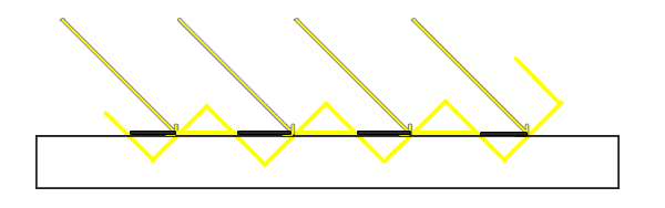
- Because shadow maps are limited by resolution, multiple clips may be sampled from the same value of the depth map at a distance from the light source. Each slope in the image represents a separate texture pixel of the depth map. You can see that multiple clips are sampled from the same depth value.
- We can use a technique called shadow bias to solve this problem. We simply apply an offset to the depth (or depth map) of the surface, so that the fragment will not be mistakenly considered below the surface.
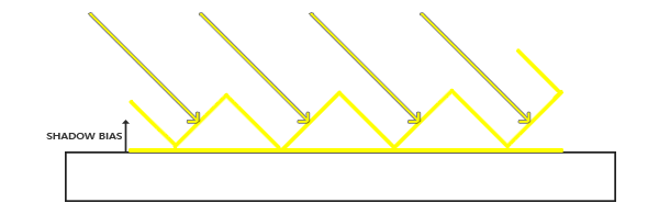
- A 0.005 offset can help a lot, but some surfaces have large slopes and still produce shadow distortion. There is a more reliable way to change the offset based on the angle of the surface towards the light: use point multiplication
- ShadowCalculation function:
float ShadowCalculation(vec4 fragPosLightSpace)
{
    // perform perspective divide
    vec3 projCoords = fragPosLightSpace.xyz / fragPosLightSpace.w;
    // transform to [0,1] range
    projCoords = projCoords * 0.5 + 0.5;
    // get closest depth value from light's perspective (using [0,1] range fragPosLight as coords)
    float closestDepth = texture(shadowMap, projCoords.xy).r;
    // get depth of current fragment from light's perspective
    float currentDepth = projCoords.z;
    // check whether current frag pos is in shadow
    // Calculate bias (based on depth map resolution and slope)
    vec3 normal = normalize(fs_in.Normal);
    vec3 lightDir = normalize(lightPos - fs_in.FragPos);
    float bias = max(0.05 * (1.0 - dot(normal, lightDir)), 0.005);
    // Check whether current frag pos is in shadow
    float shadow = currentDepth - bias > closestDepth  ? 1.0 : 0.0;
    return shadow;
}
- Here we have a maximum value of 0.05 and a minimum value of 0.005, which are based on the surface normal and illumination direction. In this way, a surface such as the floor is almost perpendicular to the light source, resulting in a small offset, while a surface such as the side of the cube has a larger offset.
suspension
- One disadvantage of using shadow offset is that you apply translation to the actual depth of the object. The offset may be large enough to see the offset of the shadow from the actual object position.
- This shadow distortion is called Peter panning because objects appear to float gently above the surface.
- We can solve most of the Peter panning problems with a technique called: use front face culling when rendering depth maps.
- Because we only need the depth value of the depth map, there is no problem for solid objects whether we use their front or back. There is no error in using the back depth, because the shadow is wrong inside the object and we can't see it.
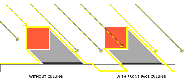
- This effectively solves the problem of peter panning, but it is only effective for solid objects that do not open internally.
Too many samples
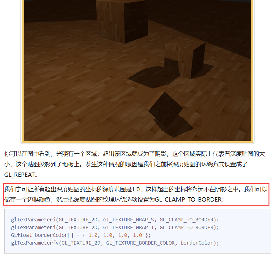
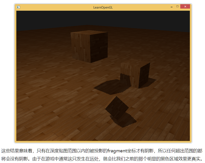
- Another visual difference is that the invisible area of the cone of light is considered to be in shadow, whether it is really in shadow.
- This happens because the projection coordinates of the cone beyond the light are larger than 1.0, so the sampled depth texture will exceed its default range of 0 to 1.
- Depending on the texture wrapping, we will get incorrect depth results, which are not based on real depth values from light sources.
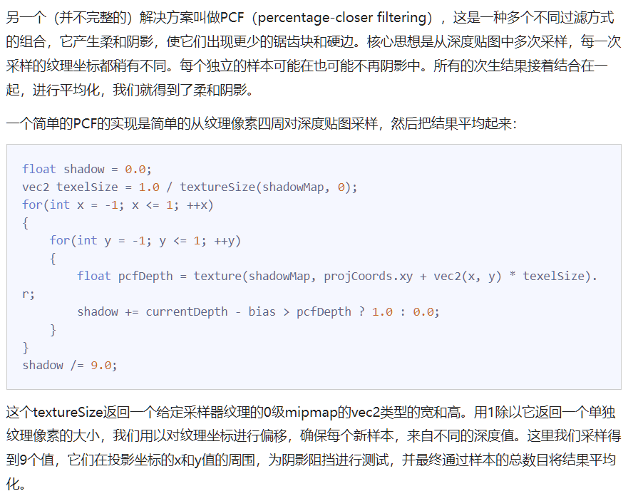
PCF
- Shadows are now attached to the scene, but that's still not what we want. If you zoom in on shadows, the dependence of shadow mapping on resolution quickly becomes apparent.
- Because the depth map has a fixed resolution, multiple clips correspond to one texture pixel. The result is that multiple clips will sample from the same depth value of the depth map, and these clips will get the same shadow, which will produce jagged edges.
- You can reduce the jagged block by increasing the resolution of the depth map, or you can try to make the cone of light as close to the scene as possible.
- In fact, it is similar to the idea of MSAA
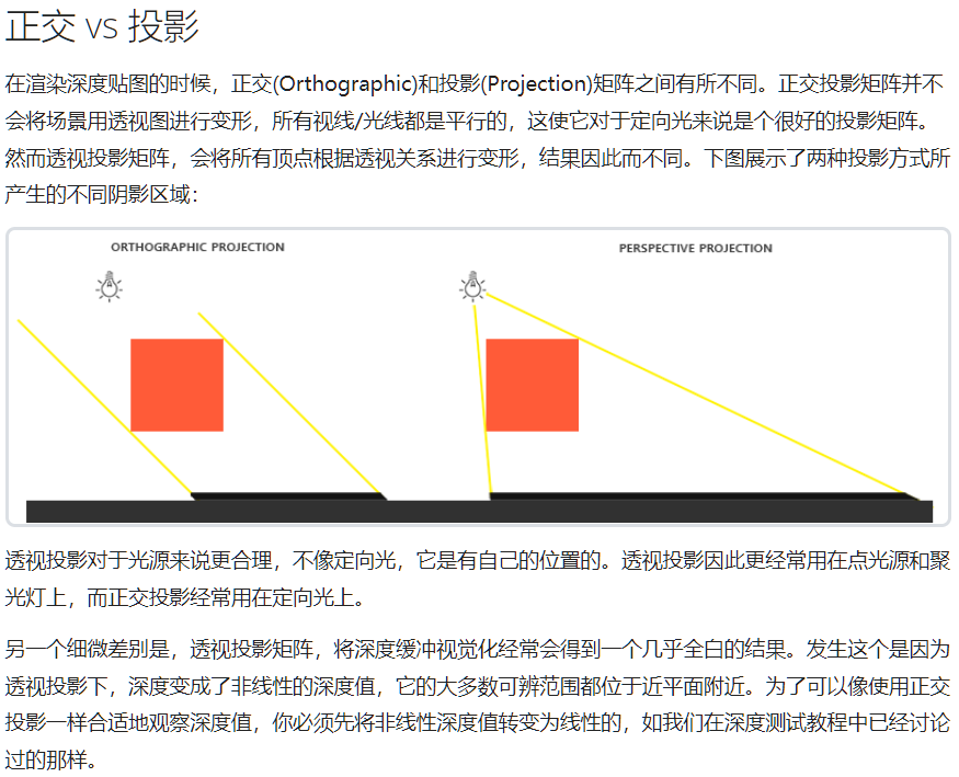
Orthogonal vs projection
5.3.2 point shadow
- The effect is good, but it is only suitable for directional light, because shadows are only generated under a single directional light source. Therefore, it is also called directional shadow mapping. Depth (shadow) mapping generates the angle of view of self-directed light.
- This technology is called point light shadow, which used to be called omnidirectional shadow maps.
- For depth map, we need to render all scenes from one point light source, and ordinary 2D depth map cannot work;
- What happens if we use cube mapping? Because the cube map can store the environment data of six faces, it can render the whole scene to each face of the cube map and sample them as the depth values around the point light source.
- The generated depth cube map is transferred to the illumination pixel shader, which samples the cube map with a direction vector to obtain the depth of the current fragment (from the perspective of the light).
Generate depth cube map
// configure depth map FBO
// -----------------------
const unsigned int SHADOW_WIDTH = 1024, SHADOW_HEIGHT = 1024;
unsigned int depthMapFBO;
glGenFramebuffers(1, &depthMapFBO);
// create depth cubemap texture
unsigned int depthCubemap;
glGenTextures(1, &depthCubemap);
glBindTexture(GL_TEXTURE_CUBE_MAP, depthCubemap);
for (unsigned int i = 0; i < 6; ++i)
    glTexImage2D(GL_TEXTURE_CUBE_MAP_POSITIVE_X + i, 0, GL_DEPTH_COMPONENT, SHADOW_WIDTH, SHADOW_HEIGHT, 0, GL_DEPTH_COMPONENT, GL_FLOAT, NULL);
glTexParameteri(GL_TEXTURE_CUBE_MAP, GL_TEXTURE_MAG_FILTER, GL_NEAREST);
glTexParameteri(GL_TEXTURE_CUBE_MAP, GL_TEXTURE_MIN_FILTER, GL_NEAREST);
glTexParameteri(GL_TEXTURE_CUBE_MAP, GL_TEXTURE_WRAP_S, GL_CLAMP_TO_EDGE);
glTexParameteri(GL_TEXTURE_CUBE_MAP, GL_TEXTURE_WRAP_T, GL_CLAMP_TO_EDGE);
glTexParameteri(GL_TEXTURE_CUBE_MAP, GL_TEXTURE_WRAP_R, GL_CLAMP_TO_EDGE);
// attach depth texture as FBO's depth buffer
glBindFramebuffer(GL_FRAMEBUFFER, depthMapFBO);
glFramebufferTexture(GL_FRAMEBUFFER, GL_DEPTH_ATTACHMENT, depthCubemap, 0);
glDrawBuffer(GL_NONE);
glReadBuffer(GL_NONE);
glBindFramebuffer(GL_FRAMEBUFFER, 0);
- Universal shadow map has two rendering stages: first, we generate depth map, and then we render with depth map normally to create shadows in the scene.
- The processing of framebuffer objects and cube maps looks like this:
// 1. first render to depth cubemap
glViewport(0, 0, SHADOW_WIDTH, SHADOW_HEIGHT);
glBindFramebuffer(GL_FRAMEBUFFER, depthMapFBO);
glClear(GL_DEPTH_BUFFER_BIT);
ConfigureShaderAndMatrices();
RenderScene();
glBindFramebuffer(GL_FRAMEBUFFER, 0);
// 2. then render scene as normal with shadow mapping (using depth cubemap)
glViewport(0, 0, SCR_WIDTH, SCR_HEIGHT);
glClear(GL_COLOR_BUFFER_BIT | GL_DEPTH_BUFFER_BIT);
ConfigureShaderAndMatrices();
glBindTexture(GL_TEXTURE_CUBE_MAP, depthCubemap);
RenderScene();
- This process is the same as the default shadow mapping, although this time we render and use a cube map depth texture instead of a 2D depth texture.
- Before we actually start rendering the scene from all directions of the light perspective, we have to calculate the appropriate transformation matrix.
Transformation of light space
// 0. create depth cubemap transformation matrices
// -----------------------------------------------
float near_plane = 1.0f;
float far_plane = 25.0f;
glm::mat4 shadowProj = glm::perspective(glm::radians(90.0f), (float)SHADOW_WIDTH / (float)SHADOW_HEIGHT, near_plane, far_plane);
std::vector<glm::mat4> shadowTransforms;
shadowTransforms.push_back(shadowProj * glm::lookAt(lightPos, lightPos + glm::vec3(1.0f, 0.0f, 0.0f), glm::vec3(0.0f, -1.0f, 0.0f)));
shadowTransforms.push_back(shadowProj * glm::lookAt(lightPos, lightPos + glm::vec3(-1.0f, 0.0f, 0.0f), glm::vec3(0.0f, -1.0f, 0.0f)));
shadowTransforms.push_back(shadowProj * glm::lookAt(lightPos, lightPos + glm::vec3(0.0f, 1.0f, 0.0f), glm::vec3(0.0f, 0.0f, 1.0f)));
shadowTransforms.push_back(shadowProj * glm::lookAt(lightPos, lightPos + glm::vec3(0.0f, -1.0f, 0.0f), glm::vec3(0.0f, 0.0f, -1.0f)));
shadowTransforms.push_back(shadowProj * glm::lookAt(lightPos, lightPos + glm::vec3(0.0f, 0.0f, 1.0f), glm::vec3(0.0f, -1.0f, 0.0f)));
shadowTransforms.push_back(shadowProj * glm::lookAt(lightPos, lightPos + glm::vec3(0.0f, 0.0f, -1.0f), glm::vec3(0.0f, -1.0f, 0.0f)));
- Because the projection matrix does not change in each direction, we can reuse it in six transformation matrices. We need to provide a different view matrix for each direction.
- Create 6 viewing directions with glm::lookAt, and each looks at one direction of the cube map in order: right, left, up, down, near and far.
Depth shader
- In order to render values to the depth cube map, we will need three shaders: vertex and pixel shaders, and a geometry shader between them.
- The geometry shader is a shader responsible for transforming the vertices of all world spaces into six different light spaces. Therefore, vertex shaders simply transform vertices into world space and then send them directly to geometry shaders.
- Then the geometry shader takes the vertices of three triangles as input, and it also has a uniform array of light space transformation matrix.
- The geometry shader is then responsible for transforming vertices into light space; It's starting to get interesting here.
- Geometry shaders have a built-in variable called gl_Layer, which specifies which side of the cube map the divergent basic shape is sent to.
- When it is ignored, the geometry shader will send its basic shape to the next stage of the conveying pipeline as usual, but when we update this variable, we can control which face of the cube map each basic shape will be rendered to.
- Of course, only when we have a valid texture attached to the cube.
- Geometry shaders are relatively simple.
- We input a triangle and output a total of 6 triangles (6 * 3 vertices, so a total of 18 vertices).
- In the main function, we traverse the six faces of the cube map. Each face is designated as an output face, and the integer of this face is saved in gl_Layer.
- Then, by multiplying the light space transformation matrix of the face by FragPos, we transform each world space vertex to the relevant light space to generate each triangle.
- Note that we also send the last FragPos variable to the pixel shader, and we need to calculate a depth value.
- Pixel Shader
- This time we will calculate our own depth, which is the linear distance between each fragment position and the light source position.
- Calculate your own depth value to make the shadow calculation more intuitive.
- The pixel shader takes the FragPos from the geometry shader, the position vector of the light, and the far plane value of the viewing cone as inputs.
- Here, we map the distance between the fragment and the light source to the range of 0 to 1, and write it as the depth value of the fragment.
- Use these shaders to render the scene. After the frame buffer object attached to the cube map is activated, you will get a fully filled depth cube map for the second stage of shadow calculation.
Universal shadow map
- Everything is done. It's time to render omnidirectional shadow.
- This process is similar to the directional shadow mapping tutorial, although this time the depth map we bound is a cube map instead of a 2D texture, and the far plane of the light projection is sent to the shader.
- Specific process strategy
Show cube map depth buffer
FragColor = vec4(vec3(closestDepth / far_plane), 1.0);
PCF
- You can use the same simple PCF filter as in the previous tutorial and add a third dimension.
- However, with samples set to 4.0, we will get a total of 64 samples per fragment, which is too much!
- Most of these samples are redundant. It is more meaningful to sample in the vertical direction of the sampling direction vector than near the original direction vector.
- A trick to use is to use an array of offset directions, which are almost separated, each pointing in a completely different direction, eliminating those sub directions close to each other.