In front, we all write our own LED lamp drivers. In fact, for very basic device drivers such as LED lamps, the Linux kernel has been integrated. The LED driver of Linux kernel adopts platform framework, Therefore, we only need to add corresponding LED nodes in the device tree file as required,
1, linux kernel comes with LED driver enable
make menuconfig
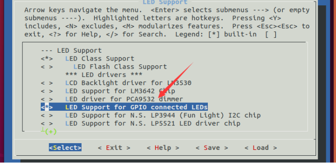
Open the LED driver configuration item according to the following path:
-> Device Drivers
-> LED Support (NEW_LEDS [=y])
->LED Support for GPIO connected LEDs
According to the above path, select "LED Support for GPIO connected LEDs" and compile it into the Linux kernel, that is, press "Y" on this option to change the front of this option to "< * >", as shown in the figure:
Recompile the Linux kernel and start the development board with the newly compiled zImage image.
2, Introduction of LED driver in linux kernel
1.LED lamp driving frame analysis
The LED driver file is / Drivers / LEDs / LEDs GPIO c. You can open the file / drivers/leds/Makefile and find the following contents:
2 # LED Core
3 obj-$(CONFIG_NEW_LEDS) += led-core.o
.....
23 obj-$(CONFIG_LEDS_GPIO_REGISTER) += leds-gpio-register.o
24 obj-$(CONFIG_LEDS_GPIO) += leds-gpio.o
25 obj-$(CONFIG_LEDS_LP3944) += leds-lp3944.o
......
Line 24, if config is defined_ LEDS_ GPIO will compile LEDs GPIO C this file
In the last section, we chose to compile the LED driver into the Linux kernel There will be a line "CONFIG_LEDS_GPIO=y" in the config file, so LEDs GPIO The C driver file will be compiled.
Next, let's take a look at LEDs GPIO C this driver file, find the following contents
236 static const struct of_device_id of_gpio_leds_match[] = {
237 { .compatible = "gpio-leds", },
238 {},
239 };
......
290 static struct platform_driver gpio_led_driver = {
291 .probe = gpio_led_probe,
292 .remove = gpio_led_remove,
293 .driver = {
294 .name = "leds-gpio",
295 .of_match_table = of_gpio_leds_match,
296 },
297 };
298
299 module_platform_driver(gpio_led_driver);
Lines 236 ~ 239 are the matching table of LED driver. There is only one matching item in this table. The compatible content is "GPIO LEDs". Therefore, the compatible attribute value of the LED lamp device node in the device tree should also be "GPIO LEDs". Otherwise, if the device and driver are not matched successfully, the driver will not work.
Lines 290-296, platform_driver driver structure variable. It can be seen that the LED driver of Linux kernel adopts the platform framework.
Line 291 shows that the probe function is gpio_led_probe, so when the driver and device match successfully, GPIO_ led_ The probe function executes.
As can be seen from line 294, the driver name is "LEDs GPIO", so there will be a file named "LEDs GPIO" in the / sys/bus/platform/drivers directory
Line 299 passes module_ platform_ The driver function registers GPIO with the Linux kernel_ led_ Driver this platform driver
2.module_platform_driver function analysis
In the previous section, we know that the LED driver will use module_ platform_ The driver function registers the platform driver with the Linux kernel. In fact, modules are widely used in the Linux kernel_ platform_ Driver to complete the operation of registering the platform driver with the Linux kernel. module_platform_driver is defined in include/linux/platform_device.h file is a macro, which is defined as follows:
221 #define module_platform_driver(__platform_driver) \
222 module_driver(__platform_driver, platform_driver_register, \
223 platform_driver_unregister)
As you can see, module_platform_driver depends on module_driver,module_ Driver is also a macro, defined in include / Linux / device H in the document, the contents are as follows:
1260 #define module_driver(__driver, __register, __unregister, ...) \
1261 static int __init __driver##_init(void) \
1262 { \
1263 return __register(&(__driver) , ##__VA_ARGS__); \
1264 } \
1265 module_init(__driver##_init); \
1266 static void __exit __driver##_exit(void) \
1267 { \
1268 __unregister(&(__driver) , ##__VA_ARGS__); \
1269 } \
1270 module_exit(__driver##_exit);
module_ platform_ After the driver (gpio_led_driver) is expanded:
static int __init gpio_led_driver_init(void)
{
return platform_driver_register (&(gpio_led_driver));
}
module_init(gpio_led_driver_init);
static void __exit gpio_led_driver_exit(void)
{
platform_driver_unregister (&(gpio_led_driver) );
}
module_exit(gpio_led_driver_exit);
Isn't the above code the standard way to register and delete platform drivers? So module_ platform_ The driver function is used to register and delete platform drivers.
3.gpio_led_probe function analysis
When the driver and device match, GPIO_ led_ The probe function will be executed. This function mainly obtains the GPIO information of LED lamps from the device tree. The contents of the reduced function are as follows:
243 static int gpio_led_probe(struct platform_device *pdev)
244 {
245 struct gpio_led_platform_data *pdata =
dev_get_platdata(&pdev->dev);
246 struct gpio_leds_priv *priv;
247 int i, ret = 0;
248
249 if (pdata && pdata->num_leds) { /* Non device tree mode */
/* Get platform_device information */
......
268 } else { /* Adopt device tree */
269 priv = gpio_leds_create(pdev);
270 if (IS_ERR(priv))
271 return PTR_ERR(priv);
272 }
273
274 platform_set_drvdata(pdev, priv);
275
276 return 0;
277 }
Lines 269-271, if using the device tree, use GPIO_ leds_ The create function extracts the device information from the device tree, and the obtained LED lamp GPIO information is saved in the return value
gpio_ leds_ The create function is as follows:
167 static struct gpio_leds_priv *gpio_leds_create(struct
platform_device *pdev)
168 {
169 struct device *dev = &pdev->dev;
170 struct fwnode_handle *child;
171 struct gpio_leds_priv *priv;
172 int count, ret;
173 struct device_node *np;
174
175 count = device_get_child_node_count(dev);
176 if (!count)
177 return ERR_PTR(-ENODEV);
178
179 priv = devm_kzalloc(dev, sizeof_gpio_leds_priv(count),
GFP_KERNEL);
180 if (!priv)
181 return ERR_PTR(-ENOMEM);
182
183 device_for_each_child_node(dev, child) {
184 struct gpio_led led = {};
185 const char *state = NULL;
186
187 led.gpiod = devm_get_gpiod_from_child(dev, NULL, child);
188 if (IS_ERR(led.gpiod)) {
189 fwnode_handle_put(child);
190 ret = PTR_ERR(led.gpiod);
191 goto err;
192 }
193
194 np = of_node(child);
195
196 if (fwnode_property_present(child, "label")) {
197 fwnode_property_read_string(child, "label", &led.name);
198 } else {
199 if (IS_ENABLED(CONFIG_OF) && !led.name && np)
200 led.name = np->name;
201 if (!led.name)
202 return ERR_PTR(-EINVAL);
203 }

204 fwnode_property_read_string(child, "linux,default-trigger",
205 &led.default_trigger);
206
207 if (!fwnode_property_read_string(child, "default-state",
208 &state)) {
209 if (!strcmp(state, "keep"))
210 led.default_state = LEDS_GPIO_DEFSTATE_KEEP;
211 else if (!strcmp(state, "on"))
212 led.default_state = LEDS_GPIO_DEFSTATE_ON;
213 else
214 led.default_state = LEDS_GPIO_DEFSTATE_OFF;
215 }
216
217 if (fwnode_property_present(child, "retain-state-suspended"))
218 led.retain_state_suspended = 1;
219
220 ret = create_gpio_led(&led, &priv->leds[priv->num_leds++],
221 dev, NULL);
222 if (ret < 0) {
223 fwnode_handle_put(child);
224 goto err;
225 }
226 }
227
228 return priv;
229
230 err:
231 for (count = priv->num_leds - 2; count >= 0; count--)
232 delete_gpio_led(&priv->leds[count]);
233 return ERR_PTR(ret);
234 }
Line 175, call device_ get_ child_ node_ The count function counts the number of child nodes. Generally, a node is created in the device tree to represent LED lights, and then a child node is created for each LED light under this node. Therefore, the number of child nodes is also the number of LED lights.
Line 183, traverse each child node to obtain the information of each child node.
Line 187, get the GPIO information used by the LED.
Lines 196 ~ 197, read the label attribute value of the child node, because the label attribute is used as the name of the LED.
Lines 204 ~ 205, obtain the "Linux, default trigger" attribute value. You can set the default function of an LED in the Linux system through this attribute, such as as being the system heartbeat indicator.
Lines 207 ~ 215, obtain the "default state" attribute value, that is, the default state attribute of the LED lamp.
Line 220, call create_ gpio_ The LED function creates LED related io. In fact, it sets the IO used by LED as output. create_gpio_led function is mainly used to initialize led_dat This gpio_led_data structure type variable, led_dat saves the operation function of LED and other contents.
About GPIO_ led_ That's all for the probe function, GPIO_ led_ The main function of the probe function is to obtain the device information of the LED lamp, and then initialize the corresponding IO according to this information and set it as output.
3, Device tree node writing
Open the document documentation / devicetree / bindings / LEDs / LEDs GPIO Txt. This document explains in detail how to write the device tree node corresponding to the Linux built-in driver,
When writing equipment nodes, we should pay attention to the following points:
① Create a node to represent LED devices, such as dtsleds. If there are multiple LED lamps on the board, each LED lamp will be used as a child node of dtsleds.
② The compatible attribute value of dtsleds node must be "GPIO LEDs".
③ . set the label attribute. This attribute is optional. Each child node has a label attribute. The label attribute generally represents the name of the LED lamp. For example, if it is distinguished by color, it is red, green, etc.
④ . each child node must set the gpios attribute value, indicating the GPIO pin used by this LED!
⑤ . you can set the "Linux, default trigger" attribute value, that is, set the default function of LED lights. You can refer to documentation / devicetree / bindings / LEDs / common Txt to view the optional functions,
For example:
Backlight: LED as backlight.
Default on: LED on
Heartbeat: LED light is used as heartbeat indicator light and can be used as system operation prompt light.
IDE disk: the LED is used as the hard disk activity indicator.
Timer: the LED light flashes periodically, driven by the timer, and the flashing frequency can be modified
⑥ . you can set the "default state" attribute value, which can be set to on, off or keep. When it is on, the LED light is on by default, when it is off, the LED light is off by default, and when it is keep, the LED light remains in the current mode.
In imx6ull luatao EMMC Add the following LED light device node to DTS:
/* LED */
	dtsleds{

		compatible = "gpio-leds";

		led0 {
			label = "red";
			gpios = <&gpio1 3 GPIO_ACTIVE_LOW>;
			default-state = "off";
		};
	};
Because the I.MX6U-ALPHA development board has only one LED0, there is only one child node LED0 under the dtsleds node. The LED0 name is red and is closed by default. After modification, save and recompile the device tree, and then start the development board with the new device tree.
4, Run test
Use the new zImage and imx6ull alientek EMMC DTB starts the development board. After starting, check whether the directory / sys/bus/platform/devices/dtsleds exists. If so, it will be in this directory, as shown in the figure:

Enter the leds directory. The contents of this directory are shown in the figure
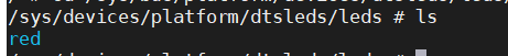
It can be seen that there is a subdirectory named "red" under the leds directory. The name of this subdirectory is the label attribute value set in line 5 of the device tree.
Whether our settings are useful or not can only be known through testing. First, check whether there is a "sys/class/leds/red/brightness" file in the system. If so, check it
Enter the following command to turn on the RED LED:
echo 1 > /sys/class/leds/red/brightness //Open LED0
The command to turn off the RED LED is as follows:
echo 0 > /sys/class/leds/red/brightness //Close LED0
If the LED lights can be turned on and off normally, it means that the LED light driver of our Linux kernel works normally. We usually use an LED light as the system indicator. If the system runs normally, the LED indicator will flash.
1. Set the LED as the system indicator
Here, we can set LED0 as the system indicator and add the "Linux, default trigger" attribute information to the dtsleds device node. The attribute value is "heartbeat". The modified dtsleds node is as follows
/* LED */
	dtsleds{

		compatible = "gpio-leds";

		led0 {
			label = "red";
			gpios = <&gpio1 3 GPIO_ACTIVE_LOW>;
			linux,default-trigger = "heartbeat";
			default-state = "on";
		};
	};
Line 7, set LED0 to heartbeat.
Line 8, LED0 is turned on by default.
Recompile the device tree and start the Linux system with the new device tree. After startup, LED0 will flash as the system heartbeat indicator, indicating that the system is running.