catalogue
- Lianshengde HLK-W806 (I): ubuntu20 04 development environment configuration, compilation and burning instructions
- Lianshengde HLK-W806 (II): description of development environment configuration, compilation and burning under Win10
- Lianshengde HLK-W806 (III): key free automatic download and reset
- Lianshengde HLK-W806 (IV): ST7735 LCD driven by software SPI and hardware SPI
- Lianshengde HLK-W806 (V): report on W801 development board
- Lianshengde HLK-W806 (VI): I2C driven SSD1306 128x64 OLED LCD
- Lianshengde HLK-W806 (VII): compatible development board LuatOS Air103
- Lianshengde HLK-W806 (VIII): 4-wire SPI driven SSD1306/SSD1315 128x64 OLED LCD
- Lianshengde HLK-W806 (IX): software SPI and hardware SPI drive ST7789V LCD
ST7789 introduction


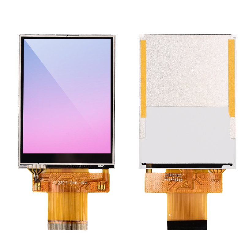
ST7789/ST7789V/ST7789H2 is used to drive 262K color image TFT-LCD on a single chip. It includes 720 (240 * 3 colors) x 320 line output. It can be directly connected to the external controller in SPI protocol or 8-bit / 9-bit / 16-bit / 18-bit parallel The display data is stored in the on-chip 240x320x18 bits memory. External clock drive is not required for reading and writing of the display memory
ST7789 has ST7789, ST7789V, ST7789H2 and other models, with resolutions of 240x204, 240x240, 240x320 and other types, and the driving mode is the same
connection
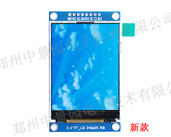
The wiring of ST7789 has 7 pins / 8 pins and 40 pins compatible with parallel port, which will be more than ST7735. One part is used for backlight LED, because the display area is larger, there are more backlight LEDs, and the other part is used for mode control The main wiring is the same as ST7735. For details, please refer to the user manual of the display screen The connection mode corresponding to this test is
- B10 -> RES, RESET
- B11 -> DC, CD
- B14 -> CS, Chip Select
- B15 -> SCK, SCL, CLK, Clock
- B16 - > BL (or LEDx), there may be multiple connections Leda, ledk, ledk1 and ledk2, which are connected to high level, low level or GPIO control according to the wiring instructions of the display screen
- B17 -> MOSI, SDA
- GND -> GND
- 3.3V -> VCC
Using this example, it is necessary to confirm that ST7789 operates in 4-wire SPI mode The control part of ST7789 is exactly the same as ST7735
Demonstrate the use of code
Demo code at wm-sdk-w806/tree/main/demo/spi/st77xx_lcd , the file structure is
.
├── ascii_fonts.c # English font file
├── ascii_fonts.h # English font header file
├── main.c        # Program entry
├── st7735.c      # Initialization method of ST7735
├── st7735.h      # Header file of ST7735
├── st7789.c      # Initialization method of ST7789
├── st7789.h      # Header file of ST7789
├── st77xx.c      # Common methods of ST7735 and ST7789
├── st77xx.h      # Common method header files for ST7735 and ST7789
├── testimg.h     # Test picture, size 128x128
├── wm_hal_msp.c  # Peripheral initialization method
└── wm_it.c       # Interrupt processing method
Delete all the files in the project app/src directory except Makefile, and copy the demo code to app/src
According to device configuration options
The demo code uses ST7735 by default, and some modifications need to be made to ST7789
st77xx.h
Set here
- ST77XX_BUF_SIZE the size of the buffer, in bytes
- ST77XX_ HARDWARE_ Whether SPI uses hardware SPI, 0: No, 1: Yes
- ST77XX__PORT and st77xx__ Selection of pin pins
You can leave the default unchanged
#define ST77XX_BUF_SIZE         1024
#define ST77XX_HARDWARE_SPI     1

// CS: B4, B14
#define ST77XX_CS_PORT      GPIOB
#define ST77XX_CS_PIN       GPIO_PIN_14
// SCK: B1, B2, B15, B24
#define ST77XX_SCK_PORT     GPIOB
#define ST77XX_SCK_PIN      GPIO_PIN_15
// MOSI: B5, B17, B26, PA7
#define ST77XX_MOSI_PORT    GPIOB
#define ST77XX_MOSI_PIN     GPIO_PIN_17
// MISO: B0, B3, B16, B25

#define ST77XX_RES_PORT     GPIOB
#define ST77XX_RES_PIN      GPIO_PIN_10
#define ST77XX_DC_PORT      GPIOB
#define ST77XX_DC_PIN       GPIO_PIN_11
#define ST77XX_BL_PORT      GPIOB
#define ST77XX_BL_PIN       GPIO_PIN_16
In the following LCD screen size and display direction color format, select the configuration suitable for your own screen, cancel the comment, and comment out the default. Be careful not to repeat the definition. If there is no suitable one, you need to define it yourself
For ST7789 TFT LCD of 240x320, you can use
#define ST77XX_WIDTH  240
#define ST77XX_HEIGHT 320
#define ST77XX_XSTART 0
#define ST77XX_YSTART 0
#define ST77XX_ROTATION (ST77XX_MADCTL_MX | ST77XX_MADCTL_MY | ST77XX_MADCTL_RGB)
main.c
In main C change "st7735.h" to "st7789.h"
#include "st7789.h"
#include "testimg.h"
Modify the initialization method in the main() method to ST7789_Init();
void main(void)
{
    //...
    ST77XX_GPIO_Init();
    SPI_Init();
    ST7789_Init();
    //...
}
Then you can compile and write to W806
Graphic methods can be referenced ST7735 this article Description of
Refresh rate of ST7789 driven by W806 SPI
In the ST7789V 240x320 LCD, test two 240x320 pictures in the main process through the following code to refresh continuously
for (uint16_t i = 0; i < 1000; i++)
{
    ST77XX_DrawImage(0, 0, 128, 160, (uint16_t *)testimage1);
    ST77XX_DrawImage(0, 0, 128, 160, (uint16_t *)testimage2);
}
printf("done");
The measured 400 refresh times are about 29.2 seconds, about 13.69 FPS. The refresh rate configured for ST7789 is 60Hz, which is not the bottleneck of ST7789
Video presentation
Video presentation: https://www.bilibili.com/video/BV1bL4y1J7X5