Windows 10 20H2
HLK-W806-V1.0-KIT
WM_SDK_W806_v0.6.0
From W806 MCU chip specification V2.0 and WM_W800_register manual V2.1
DMA controller
It supports up to 8 channels and 16 DMA request sources, and supports linked list structure and register control.
Amba2.0 standard bus interface, 8 DMA channels
Support DMA operation based on memory linked list structure
Software configuration 16 hardware request sources
Support 1,4-burst operation mode
Support byte, half word and word operations
The source and destination addresses remain unchanged or increase in order, which can be configured or operate circularly within the predefined address range
Synchronous DMA request and DMA response hardware interface timing
Function overview
DMA is used to provide high-speed data transmission between peripherals and memory and between memory and memory. Data can be moved quickly through DMA without any CPU operation. This saves CPU resources and does not affect the operation of other instructions by the CPU.
DMA is mounted on the AHB bus, supports up to 8 channels and 16 hardware peripheral request sources, and supports linked list structure and register control.
Function description
DMA channel
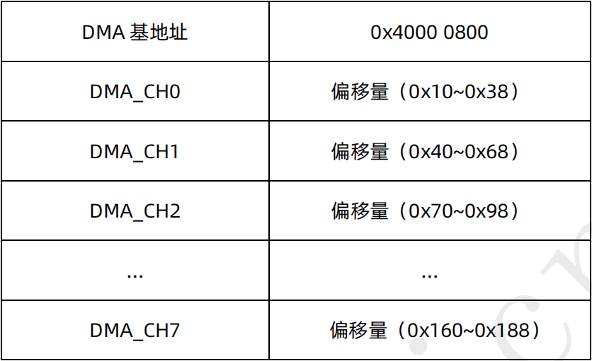
W800 supports 8 DMA channels in total. DMA channels do not interfere with each other and can operate at the same time. Different DMA channels can be selected to request different data streams.
Each DMA channel is allocated in different register address offset segments. You can directly select the address segment of the corresponding channel for configuration. The register configuration of different channels is completely consistent.
DMA data stream
8-way DMA channel can realize one-way data transmission link between source and destination.
The source and destination addresses of DMA can be set to three modes: constant, incremental or cyclic after each DMA operation:
DMA_CTRL[2:1] controls the change mode of the source address after each DMA operation;
DMA_CTRL[4:3] controls how the destination address changes after each DMA operation.
DMA can set the handling units of byte, half word and word. The number of final handling data is an integral multiple of the handling unit_ CTRL [6:5] to set.
DMA can set how many units of data are transported each time through burst_ CTRL [7] to select 1 or 4 units of data to be transported at a time, if DMA_ If Ctrl [6:5] is set to word and burst is set to 4, the data of 4 words will be transported at a time.
DMA can set the number of bytes for DMA transmission each time, with a maximum of 65535 bytes, through DMA_CTRL[23:8] to set.
DMA cycle mode
DMA cyclic address mode means that after setting the source and destination addresses of DMA, after the data handling reaches the set cyclic boundary, it will jump to the cyclic start address, and the cyclic execution will be carried out until the set transmission byte is reached.
SRC is required for source and destination addresses of cyclic address mode_ WRAP_ Addr and DEST_WRAP_ADDR register and WRAP_SIZE to set the length value of the cycle.
DMA transmission mode
DMA supports three transmission modes:
Memory to memory
The source address and destination address are configured as the memory address to be transmitted, DMA_MODE[0] is set to 0, software mode.
Memory to peripherals
The source address is set as the memory address, the destination address is set as the peripheral address, DMA_MODE[0] is set to 1, hardware mode,
DMA_MODE[5:2] select the peripheral used.
Peripheral to memory
The source address is set as the peripheral address, the destination address is set as the memory address, DMA_MODE[0] is set to 1, hardware mode, DMA_MODE[5:2] select the peripheral used.
DMA peripheral selection
When using the transmission mode of peripheral to memory or memory to peripheral, except that the corresponding peripheral needs to be set to DMA TX or RX, DMA_MODE[5:2] also needs to select the corresponding peripheral.
Note: there are three UART ports in total. When UART uses DMA, it also needs to pass UART_CH[1:0] to select the corresponding UART.
DMA linked list mode
DMA supports linked list working mode. Through the linked list mode, when DMA carries the memory data of the current linked list, we can fill the data in the next linked list in advance. After DMA moves the current linked list, it is judged that the next linked list is valid, and the data of the next linked list can be carried directly. Through the way of linked list, the efficiency of DMA and CPU cooperation can be effectively improved.
Linked list operation mode: through DMA_ The mode [1] register sets DMA to the linked list working mode, and then desc_ The addr register is set as the starting address of the linked list structure, and then through CHNL_CTRL register enables DMA. After DMA processing completes the moving of the current memory, the software notifies DMA that there is still valid data in the linked list by setting the valid flag, and DMA processes the next data to be moved according to the valid flag of the linked list.
DMA interrupt
Interrupt can be generated when DMA transmission is completed or burst, INT_MASK register can mask the interrupt corresponding to DMA channel. When the corresponding DMA interrupt is generated, it can pass int_ The SRC register queries the status of the current interrupt and indicates what interrupt is currently generated. The corresponding status bit needs to be written by the software to clear 1 and 0.
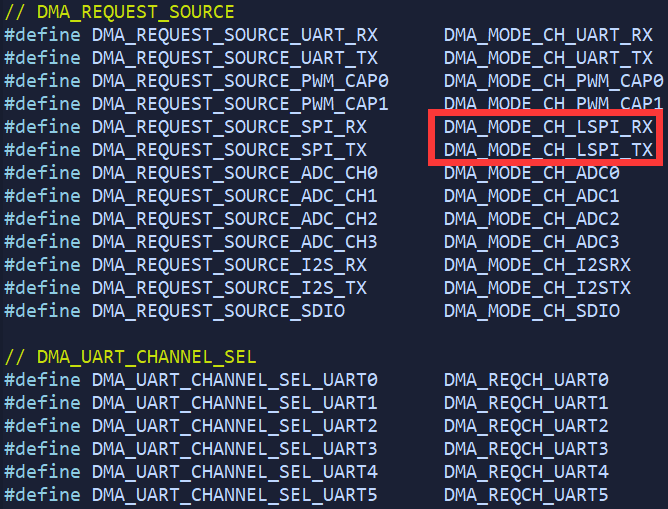
Interrupt request
It should be noted that the DMA of SPI is LSPI:
Library function
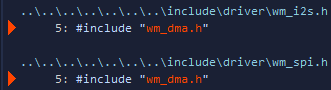
Open wm_dma.h. The contents are as follows:
function
HAL_StatusTypeDef HAL_DMA_Init(DMA_HandleTypeDef *hdma);
HAL_StatusTypeDef HAL_DMA_DeInit (DMA_HandleTypeDef *hdma);
HAL_StatusTypeDef HAL_DMA_Start (DMA_HandleTypeDef *hdma, uint32_t SrcAddress, uint32_t DstAddress, uint16_t DataLength);
HAL_StatusTypeDef HAL_DMA_Start_IT(DMA_HandleTypeDef *hdma, uint32_t SrcAddress, uint32_t DstAddress, uint16_t DataLength);
HAL_StatusTypeDef HAL_DMA_Abort(DMA_HandleTypeDef *hdma);
HAL_StatusTypeDef HAL_DMA_Abort_IT(DMA_HandleTypeDef *hdma);
HAL_StatusTypeDef HAL_DMA_PollForTransfer(DMA_HandleTypeDef *hdma, uint32_t CompleteLevel, uint32_t Timeout);
void HAL_DMA_IRQHandler(DMA_HandleTypeDef *hdma);

HAL_DMA_StateTypeDef HAL_DMA_GetState(DMA_HandleTypeDef *hdma);
uint32_t HAL_DMA_GetError(DMA_HandleTypeDef *hdma);
parameter
Structure and enumeration type
typedef enum
{
	HAL_DMA_STATE_RESET		= 0x00U,
	HAL_DMA_STATE_READY		= 0x01U,
	HAL_DMA_STATE_BUSY		= 0x02U,
	HAL_DMA_STATE_TIMEOUT	= 0x03U
}HAL_DMA_StateTypeDef;

typedef struct
{
	uint32_t Direction;				/* 	Specifies if the data will be transferred from memory to peripheral,
										from peripheral to memory or from memmory to memory.
										This parameter can be a value of @ref DMA_DATA_TRANSFER_DIRECTION*/

	uint32_t DestInc;				/*  Specifies weather the destination address should be incremented or not.
	  									When mode is DMA_MODE_NORMAL_CIRCULAR and destination address need increment,
										must choose DMA_DINC_CIRCULAR.
	  									This parameter can be a value of @ref DMA_DEST_ADDR_INCREMENT*/

	uint32_t SrcInc;				/* 	Specifies weather the source address should be incremented or not.
	  									When mode is DMA_MODE_NORMAL_CIRCULAR and Source address need increment,
										must choose DMA_SINC_CIRCULAR.
	  									This parameter can be a value of @ref DMA_SRC_ADDR_INCREMENT*/

	uint32_t DataAlignment;			/*  Specifies the transport unit.
	  									This parameter can be a value of @ref DMA_DATAALIGN*/

	uint32_t Mode;					/*  Specifies the operation mode of the DMA channelx. When you need to
	  									use half-complete interrupts, you must use link mode.
	  									This parameter can be a value of @ref DMA_MODE*/

	uint32_t RequestSourceSel;		/*  Specifies the request source of DMA.
										This parameter can be a value of @ref DMA_REQUEST_SOURCE*/

    uint32_t RequestUartSel;		/*  Specifies the UART number when the RequestSourceSel is DMA_REQUEST_SOURCE_UART_RX
									    or DMA_REQUEST_SOURCE_UART_TX. This parameter can be a value of @ref DMA_UART_CHANNEL_SEL*/

} DMA_InitTypeDef;

/* The descriptor structure is used internally by the driver layer,
   and the user layer does not need to be assigned. */
typedef struct __DMA_LinkDescriptor
{
	uint32_t Valid;					/*  According to the Bit31 to indicate whether the data pointed to by the
										descriptor is valid. Bit31 equal to 1 means valid, equal to 0 means invalid */

	uint32_t Control;				/*  Equal to the value of register CR2[23:1] */

	uint32_t SrcAddr;				/*  Data source address */

	uint32_t DestAddr;				/*  Data destinathion address */

	struct __DMA_LinkDescriptor *Next;	/*	Point to the address of the next descriptor structure */

} DMA_LinkDescriptor;

typedef enum
{
	HAL_DMA_HALF_TRANSFER = 0,
	HAL_DMA_FULL_TRANSFER = 1
} HAL_DMA_LevelCompleteTypeDef;

typedef struct __DMA_HandleTypeDef
{
	DMA_Channel_TypeDef		*Instance;		/* Register base address of the channel used.
											   Need user layer assignment.*/

	DMA_InitTypeDef			Init;			/* DMA communication parameters. Need user layer assignment*/

	HAL_LockTypeDef			Lock;			/* DMA locking object. */

	HAL_DMA_StateTypeDef	State;			/* DMA transfer state. */

	void					*Parent;		/* Parent object state. Need user layer assignment*/

	void					(* XferHalfCpltCallback)( struct __DMA_HandleTypeDef * hdma); /* DMA transfer complete callback. */

	void					(* XferCpltCallback)( struct __DMA_HandleTypeDef * hdma);	/* DMA Half transfer complete callback. */

	void					(* XferAbortCallback)( struct __DMA_HandleTypeDef * hdma);	/* DMA transfer abort callback. */

	DMA_TypeDef				*DmaBaseAddress;	/* DMA register base address. */

	uint32_t				ChannelIndex;		/* DMA Channel Index. */

	__IO uint32_t			ErrorCode;			/* DMA error code. */

	DMA_LinkDescriptor		*LinkDesc;			/* Points to the descriptor address. When user need to use the
												   DMA half-completed interrupt, assign a value in the user layer.
												   E.g DMA_LinkDescriptor desc[2], Size must be 2. */

	uint32_t				offset;				/* For internal use, the user does not need to assign a value. */

} DMA_HandleTypeDef;
Macro parameters
// DMA register base address and channel base address.
#define DMA					((DMA_TypeDef *)DMA_BASE)
#define DMA_Channel0		((DMA_Channel_TypeDef *)DMA_Channel0_BASE)
#define DMA_Channel1		((DMA_Channel_TypeDef *)DMA_Channel1_BASE)
#define DMA_Channel2		((DMA_Channel_TypeDef *)DMA_Channel2_BASE)
#define DMA_Channel3		((DMA_Channel_TypeDef *)DMA_Channel3_BASE)
#define DMA_Channel4		((DMA_Channel_TypeDef *)DMA_Channel4_BASE)
#define DMA_Channel5		((DMA_Channel_TypeDef *)DMA_Channel5_BASE)
#define DMA_Channel6		((DMA_Channel_TypeDef *)DMA_Channel6_BASE)
#define DMA_Channel7		((DMA_Channel_TypeDef *)DMA_Channel7_BASE)

// DMA Error Code
#define HAL_DMA_ERROR_NONE			0x0U	// No error
#define HAL_DMA_ERROR_NO_XFER		0x1U	// no ongoing transfer
#define HAL_DMA_ERROR_TIMEOUT		0x2U	// Timout error
#define HAL_DMA_ERROR_NOT_SUPPORTED	0x4U	// Not supported mode

// DMA_DATA_TRANSFER_DIRECTION
#define DMA_PERIPH_TO_MEMORY		((uint32_t)DMA_MODE_SHM)	// Peripheral to memory direction
#define DMA_MEMORY_TO_PERIPH		((uint32_t)DMA_MODE_SHM)	// Memory to peripheral direction
#define DMA_MEMORY_TO_MEMORY		0x00000000U					// Memory to memory direction

// DMA_DEST_ADDR_INCREMENT
#define DMA_DINC_ENABLE				((uint32_t)DMA_CR2_DINC_ENABLE)		// Destination address increment mode Enable
#define DMA_DINC_DISABLE			((uint32_t)DMA_CR2_DINC_DISABLE)	// Destination address increment mode Disable
#define DMA_DINC_CIRCULAR			((uint32_t)DMA_CR2_DINC_CYCLE)		// Destination address circular mode. Only when Mode = DMA_MODE_NORMAL_CIRCULAR

// DMA_SRC_ADDR_INCREMENT
#define DMA_SINC_ENABLE				((uint32_t)DMA_CR2_SINC_ENABLE)		// Source address increment mode Enable
#define DMA_SINC_DISABLE			((uint32_t)DMA_CR2_SINC_DISABLE)	// Source address increment mode Disable
#define DMA_SINC_CIRCULAR			((uint32_t)DMA_CR2_SINC_CYCLE)		// Source address circular mode. Only when Mode = DMA_MODE_NORMAL_CIRCULAR

// DMA_DATAALIGN
#define DMA_DATAALIGN_BYTE			((uint32_t)DMA_CR2_TRANS_SIZE_BYTE)			// Memory data alignment: Byte
#define DMA_DATAALIGN_HALFWORD		((uint32_t)DMA_CR2_TRANS_SIZE_HALFWORD)		// Memory data alignment: HalfWord
#define DMA_DATAALIGN_WORD			((uint32_t)DMA_CR2_TRANS_SIZE_WORD)			// Memory data alignment: Word

// DMA_MODE
#define DMA_MODE_NORMAL_SINGLE				0x00000000U				// Normal single mode
#define DMA_MODE_NORMAL_CIRCULAR			0x00000001U				// Normal circular mode
#define DMA_MODE_LINK_SINGLE				0x00000002U				// Link	singal mode
#define DMA_MODE_LINK_CIRCULAR				0x00000003U				// Link circular mode

// DMA_INTERRUPT_TYPE
#define DMA_FLAG_TF_DONE			DMA_IF_TRANSFER_DONE			// Transfer complete interrupt
#define DMA_FLAG_BURST_DONE			DMA_IF_BURST_DONE				// Burst complete interrupt

// DMA_REQUEST_SOURCE
#define DMA_REQUEST_SOURCE_UART_RX		DMA_MODE_CH_UART_RX
#define DMA_REQUEST_SOURCE_UART_TX		DMA_MODE_CH_UART_TX
#define DMA_REQUEST_SOURCE_PWM_CAP0		DMA_MODE_CH_PWM_CAP0
#define DMA_REQUEST_SOURCE_PWM_CAP1		DMA_MODE_CH_PWM_CAP1
#define DMA_REQUEST_SOURCE_SPI_RX		DMA_MODE_CH_LSPI_RX
#define DMA_REQUEST_SOURCE_SPI_TX		DMA_MODE_CH_LSPI_TX
#define DMA_REQUEST_SOURCE_ADC_CH0		DMA_MODE_CH_ADC0
#define DMA_REQUEST_SOURCE_ADC_CH1		DMA_MODE_CH_ADC1
#define DMA_REQUEST_SOURCE_ADC_CH2		DMA_MODE_CH_ADC2
#define DMA_REQUEST_SOURCE_ADC_CH3		DMA_MODE_CH_ADC3
#define DMA_REQUEST_SOURCE_I2S_RX		DMA_MODE_CH_I2SRX
#define DMA_REQUEST_SOURCE_I2S_TX		DMA_MODE_CH_I2STX
#define DMA_REQUEST_SOURCE_SDIO			DMA_MODE_CH_SDIO

// DMA_UART_CHANNEL_SEL
#define DMA_UART_CHANNEL_SEL_UART0		DMA_REQCH_UART0
#define DMA_UART_CHANNEL_SEL_UART1		DMA_REQCH_UART1
#define DMA_UART_CHANNEL_SEL_UART2		DMA_REQCH_UART2
#define DMA_UART_CHANNEL_SEL_UART3		DMA_REQCH_UART3
#define DMA_UART_CHANNEL_SEL_UART4		DMA_REQCH_UART4
#define DMA_UART_CHANNEL_SEL_UART5		DMA_REQCH_UART5
macro
#define IS_DMA_ALL_INSTANCE(INSTANCE)	(((INSTANCE) == DMA_Channel0) || \
										 ((INSTANCE) == DMA_Channel1) || \
										 ((INSTANCE) == DMA_Channel2) || \
										 ((INSTANCE) == DMA_Channel3) || \
										 ((INSTANCE) == DMA_Channel4) || \
										 ((INSTANCE) == DMA_Channel5) || \
										 ((INSTANCE) == DMA_Channel6) || \
										 ((INSTANCE) == DMA_Channel7))

#define IS_DMA_DIRECTION(DIRECTION)		(((DIRECTION) == DMA_PERIPH_TO_MEMORY) || \
										 ((DIRECTION) == DMA_MEMORY_TO_PERIPH) || \
										 ((DIRECTION) == DMA_MEMORY_TO_MEMORY))

#define IS_DMA_DEST_INC_STATE(STATE)	(((STATE) == DMA_DINC_ENABLE) || \
											 ((STATE) == DMA_DINC_DISABLE))

#define IS_DMA_SRC_INC_STATE(STATE)		(((STATE) == DMA_SINC_ENABLE) || \
											 ((STATE) == DMA_SINC_DISABLE))

#define IS_DMA_DATA_SIZE(SIZE)			(((SIZE) == DMA_DATAALIGN_BYTE) || \
										 ((SIZE) == DMA_DATAALIGN_HALFWORD) || \
										 ((SIZE) == DMA_DATAALIGN_WORD))

#define IS_DMA_MODE(MODE)				(((MODE) == DMA_MODE_NORMAL_SINGLE) || \
										 ((MODE) == DMA_MODE_NORMAL_CIRCULAR) || \
										 ((MODE) == DMA_MODE_LINK_SINGLE) || \
										 ((MODE) == DMA_MODE_LINK_CIRCULAR))

#define IS_DMA_REQUEST_SOURCE(SEL)		(((SEL) == DMA_REQUEST_SOURCE_UART_RX) || \
										 ((SEL) == DMA_REQUEST_SOURCE_UART_TX) || \
										 ((SEL) == DMA_REQUEST_SOURCE_PWM_CAP0) || \
										 ((SEL) == DMA_REQUEST_SOURCE_PWM_CAP1) || \
										 ((SEL) == DMA_REQUEST_SOURCE_SPI_RX) || \
										 ((SEL) == DMA_REQUEST_SOURCE_SPI_TX) || \
										 ((SEL) == DMA_REQUEST_SOURCE_ADC_CH0) || \
										 ((SEL) == DMA_REQUEST_SOURCE_ADC_CH1) || \
										 ((SEL) == DMA_REQUEST_SOURCE_ADC_CH2) || \
										 ((SEL) == DMA_REQUEST_SOURCE_ADC_CH3) || \
										 ((SEL) == DMA_REQUEST_SOURCE_I2S_RX) || \
										 ((SEL) == DMA_REQUEST_SOURCE_I2S_TX) || \
										 ((SEL) == DMA_REQUEST_SOURCE_SDIO))

#define IS_DMA_UART_CHANNEL(CHANNEL)	(((CHANNEL) == DMA_UART_CHANNEL_SEL_UART0) || \
										 ((CHANNEL) == DMA_UART_CHANNEL_SEL_UART1) || \
										 ((CHANNEL) == DMA_UART_CHANNEL_SEL_UART2) || \
										 ((CHANNEL) == DMA_UART_CHANNEL_SEL_UART3) || \
										 ((CHANNEL) == DMA_UART_CHANNEL_SEL_UART4) || \
										 ((CHANNEL) == DMA_UART_CHANNEL_SEL_UART5))

#define IS_DMA_BUFFER_SIZE(SIZE)		(((SIZE) >= 0x1U) && ((SIZE) < 0x10000U))

#define IS_DMA_SRC_ADDR(SRC)			(((SRC) % 4) == 0)

#define IS_DMA_DEST_ADDR(DEST)			(((DEST) % 4) == 0)

#define IS_DMA_LENGTH(DATAALIGN, LEN)	((((DATAALIGN) == DMA_DATAALIGN_BYTE) && (((LEN) % 1) == 0)) || \
										 (((DATAALIGN) == DMA_DATAALIGN_HALFWORD) && (((LEN) % 2) == 0)) || \
										 (((DATAALIGN) == DMA_DATAALIGN_WORD) && (((LEN) % 4) == 0)))

#define IS_DMA_LINK_LENGTH(LEN)			(((LINK) % 8) == 0)

#define IS_DMA_COMPLETELEVEL(LEVEL)		(((LEVEL) == HAL_DMA_HALF_TRANSFER) || ((LEVEL) = HAL_DMA_FULL_TRANSFER))

#define __HAL_DMA_ENABLE(__HANDLE__)	(SET_BIT((__HANDLE__)->Instance->CR1, DMA_CR1_START))

#define __HAL_DMA_DISABLE(__HANDLE__)	do {													 \
											SET_BIT((__HANDLE__)->Instance->CR1, DMA_CR1_STOP);  \
											while ((__HANDLE__)->Instance->CR1 & DMA_CR1_START); \
										} while (0)

#define __HAL_DMA_ENABLE_IT(__HANDLE__, __INTERRUPT__)	(CLEAR_BIT((__HANDLE__)->DmaBaseAddress->IM, (__INTERRUPT__)))

#define __HAL_DMA_DISABLE_IT(__HANDLE__, __INTERRUPT__)	(SET_BIT((__HANDLE__)->DmaBaseAddress->IM, (__INTERRUPT__)))

#define __HAL_DMA_GET_FLAG(__HANDLE__, __FLAG__)	(((__HANDLE__)->DmaBaseAddress->IF) & (__FLAG__))

#define __HAL_DMA_CLEAR_FLAG(__HANDLE__, __FLAG__)	(SET_BIT((__HANDLE__)->DmaBaseAddress->IF, (__FLAG__)))
application
In WM_ SDK_ W806_ v0. In 6.0, only SPI and I2S have specific DMA implementation:
The application of SPI is shown in [lianshengde W806 starting notes] VIII. SPI and DMA