Six LSA S of ospf
Class I LSA, router LSA
It is sent by each ospf router and flooded in its area. It is used to describe the status and cost value of all ospf direct interfaces of the router
View command: dis ospf lsdb router 1.1.1.1
Class II LSA, network LSA
It is generated by DR and flooded in its area. It is used to describe the rids of all ospf routers and their own rids
View command: dis ospf lsdb network 1.1.1.1
Class III LSA, network Summary LSA
It is generated by ABR and used for ospf inter region. It is used to describe the calculation of ospf inter region routing
View command: dis ospf lsdb summary 1.1.1.1
Category IV LSA, ASBR summary LSA
Generated by ABR and flooded in ospf area, used to describe ASBR
View command: dis ospf lsdb asbr 1.1.1.1
Class V LSA, AS external LSA
It is generated by ASBR and used to announce external routes between two different protocol areas
View command: dis ospf lsdb ase 1.1.1.1
Special area, LSA VII
Generated by ASBR and flooded in special areas, such as NSSA area, to announce external routes
View command: dis ospf lsdb nssa 1.1.1.1
experiment
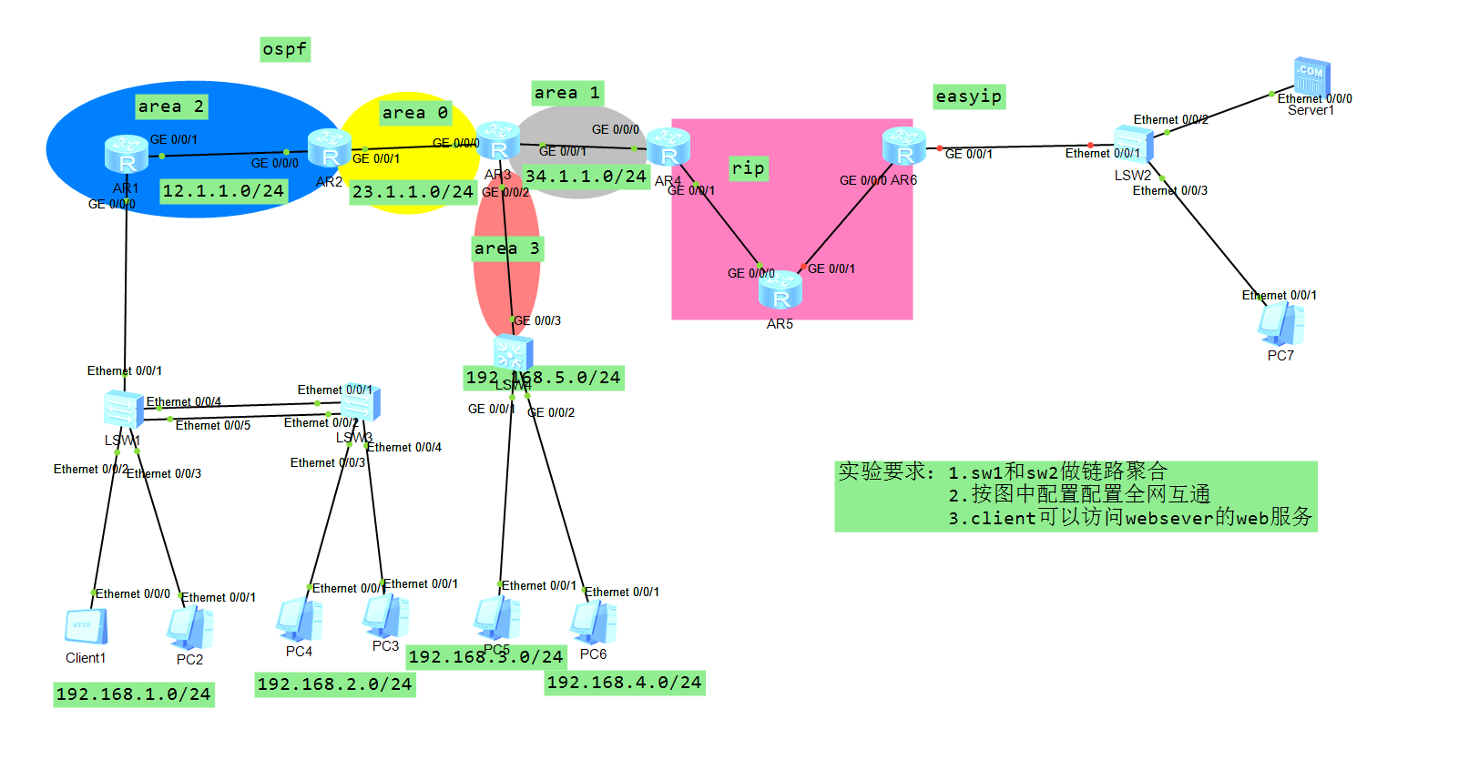
First, all interfaces of the router are equipped with IP addresses, which are displayed in SW1 Link aggregation is configured on SW3 and lacp mode is adopted
[sw1]
#
interface Eth-Trunk1
 port link-type trunk
 port trunk allow-pass vlan 2 to 4094
 mode lacp-static
[sw3]
#
interface Eth-Trunk1
 port link-type trunk
 port trunk allow-pass vlan 2 to 4094
 mode lacp-static
#
Check etrunk 1 to see that it is enabled
[sw3]dis et 1
Eth-Trunk1's state information is:
Local:
LAG ID: 1                   WorkingMode: STATIC
Preempt Delay: Disabled     Hash arithmetic: According to SIP-XOR-DIP
System Priority: 32768      System ID: 4c1f-ccc1-328f
Least Active-linknumber: 1  Max Active-linknumber: 8
Operate status: up          Number Of Up Port In Trunk: 2
--------------------------------------------------------------------------------
ActorPortName          Status   PortType PortPri PortNo PortKey PortState Weight
Ethernet0/0/1          Selected 100M     32768   2      289     10111100  1
Ethernet0/0/2          Selected 100M     32768   3      289     10111100  1

Partner:
--------------------------------------------------------------------------------
ActorPortName          SysPri   SystemID        PortPri PortNo PortKey PortState
Ethernet0/0/1          32768    4c1f-cc28-2e08  32768   5      289     10111100
Ethernet0/0/2          32768    4c1f-cc28-2e08  32768   6      289     10111100
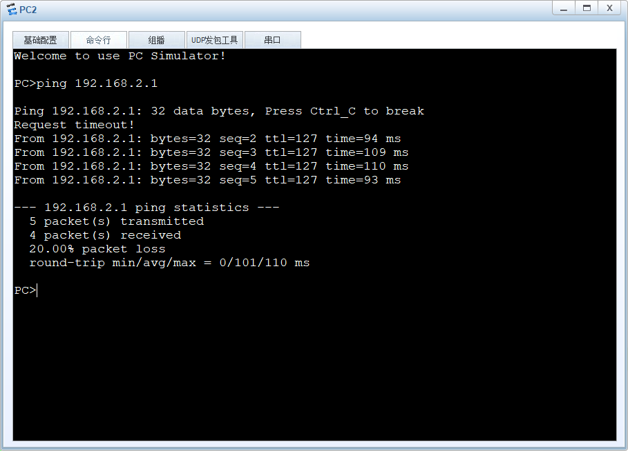
Configure single arm routing on R1 so that 1.0 and 2.0 network segments can communicate
[R1]
#
interface GigabitEthernet0/0/0.1
 dot1q termination vid 10
 ip address 192.168.1.254 255.255.255.0
 arp broadcast enable
#
interface GigabitEthernet0/0/0.2
 dot1q termination vid 20
 ip address 192.168.2.254 255.255.255.0
 arp broadcast enable
#
Configure two vlanif ports on sw4 as gateways
[sw4]
#
interface Vlanif30
 ip address 192.168.3.254 255.255.255.0
#
interface Vlanif40
 ip address 192.168.4.254 255.255.255.0
#
interface Vlanif50
 ip address 192.168.5.1 255.255.255.0
#
Configure ospf protocol on sw4 and redistribute the direct network disconnection into ospf
#
ospf 1 router-id 5.5.5.5
 import-route direct
 area 0.0.0.3
  network 192.168.5.0 0.0.0.255
#
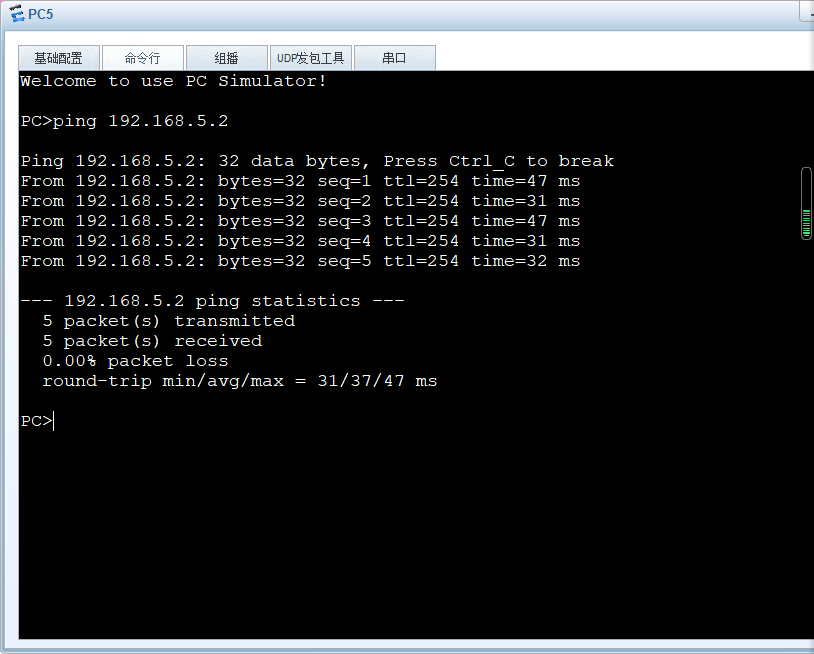
Enable it to ping the router interface connected on sw4
Configure ospf protocol on R1, R2, R3 and R4 according to the figure
[R1]
#
ospf 1 router-id 1.1.1.1
 area 0.0.0.2
  network 12.1.1.0 0.0.0.255
  network 192.168.0.0 0.0.255.255
#
<R2>
#
ospf 1 router-id 2.2.2.2
 area 0.0.0.0
  network 23.1.1.0 0.0.0.255
 area 0.0.0.2
  network 12.1.1.0 0.0.0.255
#
<R3>
#
ospf 1 router-id 3.3.3.3
 area 0.0.0.0
  network 23.1.1.0 0.0.0.255
 area 0.0.0.1
  network 34.1.1.0 0.0.0.255
 area 0.0.0.3
  network 192.168.5.0 0.0.0.255
#
ospf 1 router-id 4.4.4.4
 area 0.0.0.1
  network 34.1.1.0 0.0.0.255
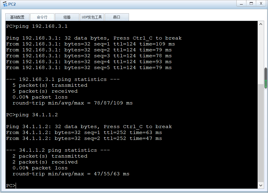
At this time, the whole ospf network can be interconnected
Reconfigure the rip area and configure the rip protocol on R4, R5 and R6
<R4>
#
rip 1
 version 2
 network 45.0.0.0
[R5]
#
rip 1
 version 2
 network 45.0.0.0
 network 56.0.0.0
#
<R6>
#
rip 1
 version 2
 network 56.0.0.0
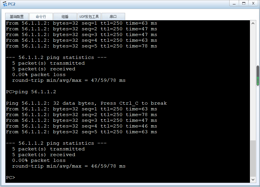
At this time, the whole network in the rip area is interconnected
<R4>ping 56.1.1.2
  PING 56.1.1.2: 56  data bytes, press CTRL_C to break
    Reply from 56.1.1.2: bytes=56 Sequence=1 ttl=254 time=30 ms
    Reply from 56.1.1.2: bytes=56 Sequence=2 ttl=254 time=20 ms
    Reply from 56.1.1.2: bytes=56 Sequence=3 ttl=254 time=20 ms
    Reply from 56.1.1.2: bytes=56 Sequence=4 ttl=254 time=20 ms
    Reply from 56.1.1.2: bytes=56 Sequence=5 ttl=254 time=10 ms

  --- 56.1.1.2 ping statistics ---
    5 packet(s) transmitted
    5 packet(s) received
    0.00% packet loss
    round-trip min/avg/max = 10/20/30 ms
<R4>
Redistribute ospf and rip on AS boundary router R4
[R4]
#
ospf 1 router-id 4.4.4.4
 import-route rip 1
 area 0.0.0.1
  network 34.1.1.0 0.0.0.255
#
rip 1
 version 2
 network 45.0.0.0
 import-route ospf 1
#
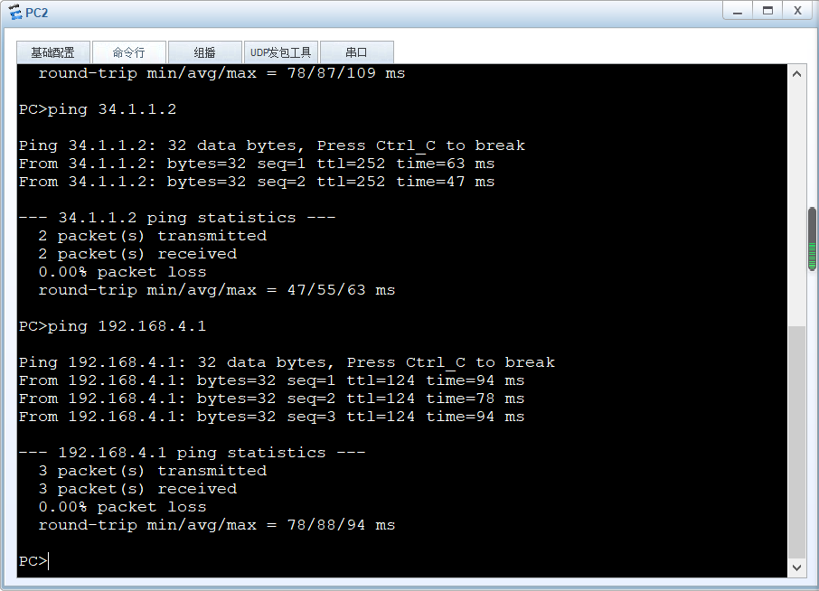
At this time, pc2 can ping R6
Then redistribute the R6 connected direct network segment into the rip
<R6>
#
rip 1
 version 2
 network 56.0.0.0
 import-route direct
#
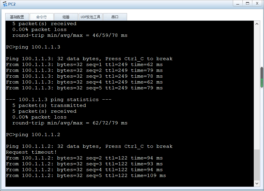
At this time, the whole network can be interconnected
Make easyip on R6 so that client s can access websever's web services
<R6>
#
acl number 2000
 rule 5 permit
 #
interface GigabitEthernet0/0/1
 ip address 100.1.1.1 255.255.255.0
 nat outbound 2000
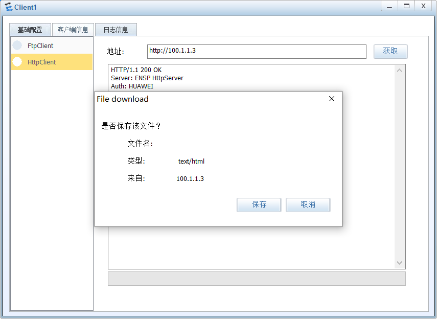
See that you can access the server
Experimental summary: if you want to communicate between two different protocols, you need to redistribute the configuration, and the direct network segment can also redistribute.