Article catalog
- 13 CAN programming application development
- 13.1 CAN introduction
- 13.2 CAN programming framework creation
- 13.3 STM32 CAN Application Programming
- 13.4 basic application programming of Linux socketcan
- 13.5 application of CAN bus in automobile industry
13CAN programming application development
13.1 CAN introduction
13.1. 1 what is can?
CAN, fully known as "Controller Area Network", namely Controller Area Network, is one of the most widely used fieldbuses in the world.
Initially, CAN was designed as a microcontroller communication in the automotive environment to exchange information between on-board electronic control devices and ECU s to form the automotive environment
Electronic control network. For example, CAN control devices are embedded in engine management system, transmission controller, instrument equipment and electronic backbone system
Set.
In a single network composed of CAN bus, countless nodes can be connected in theory. In practical application, the number of nodes is affected by the network hardware
Limited by the electrical characteristics of. For example, when Philips P82C250 is used as a CAN transceiver, 110 nodes are allowed to be connected in the same network.
CAN can provide data transmission rate up to 1Mbit/s, which makes real-time control very easy. In addition, the error verification characteristics of hardware are also increased
The anti electromagnetic interference ability of CAN is strengthened.
13.1. 2 origin of can
CAN first appeared in the automotive industry in the late 1980s and was first proposed by Bosch Company of Germany. At that time, due to consumers' enthusiasm for cars
There are more and more requirements for energy, and the realization of these functions is mostly based on electronic operation, which makes the communication between electronic devices more and more complex,
It also means that more connecting signal lines are required. The original motivation of CAN bus is to solve the huge electronic control equipment in modern vehicles
Communication between devices to reduce the increasing number of signal lines. Therefore, they designed a single network bus, and all peripheral devices can be used
Attach to the bus. In 1993, CAN has become the international standard iso11898 (high speed application) and iso111519 (low speed application).
CAN is a serial communication bus with multi master mode. The basic design specification requires high bit rate, high anti electromagnetic interference and CAN detect
Any errors are detected. When the signal transmission distance reaches 10Km, CAN can still provide data transmission rate up to 50Kbit/s.
Because CAN bus has high real-time performance, CAN has been used in automobile industry, aviation industry, industrial control, safety protection and so on
Domain has been widely used.
13.1.3 CAN transmission model
CAN communication protocol mainly describes the information transmission mode between devices. The definition of CAN layer is consistent with the open systems interconnection model (OSI)
One layer communicates with the same layer on another device. The actual communication occurs on two adjacent layers of each device, and the device only passes through the physical model
Physical medium interconnection of layers. The specification of CAN defines the lowest two layers of the model: data link layer and physical layer. The following table shows OSI open
Each layer of the interconnection model. The application layer protocol CAN be defined by CAN users into any scheme suitable for special industrial fields. It has been used in industrial control and manufacturing
The widely used standard in the manufacturing field is DeviceNet, which is designed for PLC and intelligent sensor. In the automotive industry, many manufacturers
Apply their own standards.
Table OSI development system interconnection model | ||
|---|---|---|
Serial number | arrangement | describe |
7 | application layer | The highest level. It is used for information exchange among users, software, network terminals, etc. |
6 | Presentation layer | Convert the information of two systems using different data formats into a format that can be understood jointly |
5 | Session layer | Rely on low-level communication functions for effective data transmission. |
4 | Transport layer | Data transmission control between two communication nodes. Operations such as data retransmission and data error repair |
3 | network layer | It specifies the protocol for the establishment, maintenance and removal of network connections. Such as routing and addressing |
2 | data link layer | Specifies the arrangement and organization of data bits transmitted on the medium. Such as data checksum frame structure |
1 | physical layer | Specify the physical characteristics of the communication medium. E.g. explanation of electrical characteristics and signal exchange |
Although the can transmission protocol refers to the OSI seven layer model, in fact, the CAN protocol only defines two layers of "physical layer" and "data link layer", so there are various "application layer" protocols, such as fieldbus standard DeviceNet for automation technology, CanOpen for industrial control, and diagnostic protocol OBD for passenger cars UDS (Unified diagnostic service, ISO14229), can bus protocol SAEJ1939 for commercial vehicles
Table CAN | ||
|---|---|---|
Serial number | arrangement | describe |
7 | application layer | It mainly defines the CAN application layer. |
2 | data link layer | The data link layer is divided into logical link control sublayer LLC and media access control sublayer Mac. MAC sublayer is the core of CAN protocol. It provides the received message to the LLC sublayer and receives the message from the LLC sublayer. The MAC sublayer is responsible for message framing, arbitration, response, error detection and calibration. The MAC sublayer is also referred to as the management entity of fault definition. The LLC sublayer involves message filtering, overload notification, and recovery management. LLC = Logical Link Control MAC = Medium Access Control |
1 | physical layer | The physical layer is the physical coding sublayer PCS. this layer defines how signals are actually transmitted, so it involves in place time, bit coding and synchronization. |
13.1.4 CAN network topology
CAN bus is a distributed control bus.
As a controller area network, CAN bus is composed of many CAN nodes like ordinary Ethernet.
The network topology is shown in the figure below:
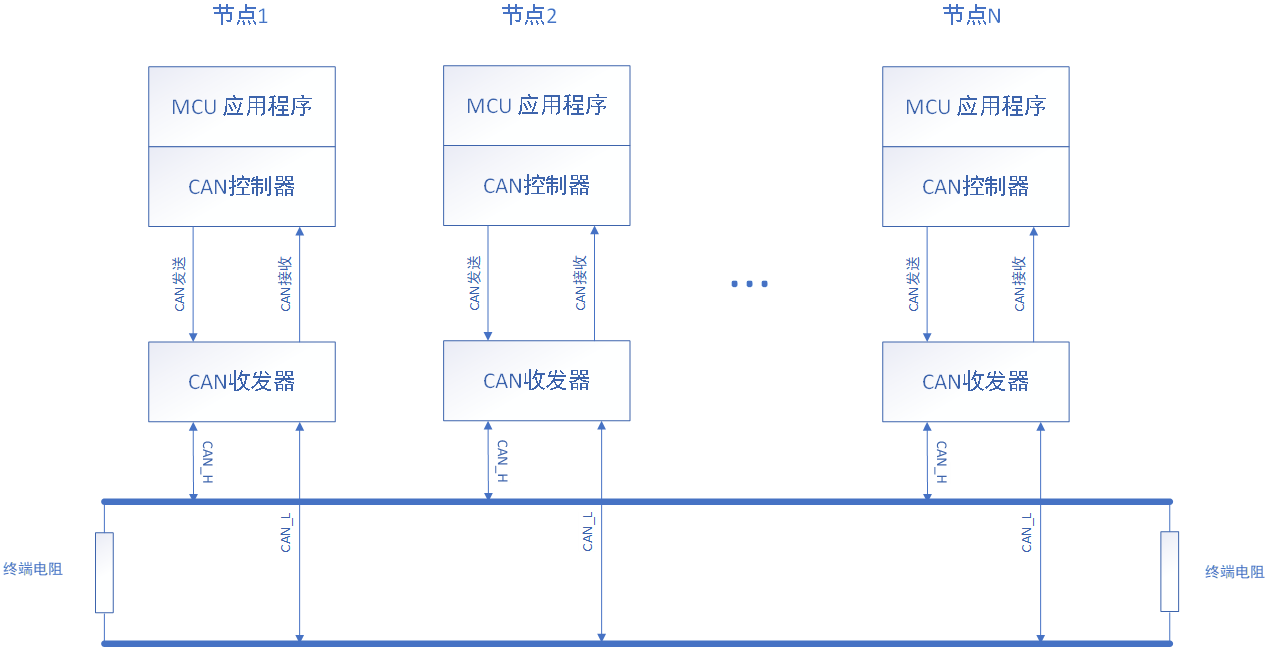
Each node of the CAN network is very simple, which is composed of a MCU (microcontroller), a CAN controller and a CAN transceiver, and then connected to the CAN network with twisted pair.
13.1.5 CAN physical characteristics
CAN bus complies with international standards ISO11898, such as ISO11898-1, ISO11898-2, ISO11898-3 and ISO11898-4.
Serial number | standard | describe |
|---|---|---|
1 | ISO11898-1 | Data link layer and physical layer signals |
2 | ISO11898-2 | High speed access unit |
3 | ISO11898-3 | Low speed fault tolerant access unit |
4 | ISO11898-4 | Time triggered communication |
5 | ISO11898-5 | Low power access unit |
6 | ISO11898-6 | Selective wake-up high speed access unit |
CAN can use a variety of physical media, such as twisted pair, optical fiber, etc. The most commonly used is twisted pair.
The signal is transmitted using differential voltage, and the two signal lines are called "CAN_H" and "CAN_L".
Static CAN_H and CAN_L is about 2.5V. At this time, the state is represented as logic "1", which can also be called "recessive".
With CAN_H ratio CAN_L high indicates logic "0", which is called "explicit". At this time, the normal voltage value is: CAN_H = 3.5V and CAN_L
= 1.5V .
At present, the commonly used CAN transceivers are as follows:
Serial number | model | describe |
|---|---|---|
1 | PCA82C250 | High speed CAN transceiver |
2 | PCA82C251 | High speed CAN transceiver |
3 | PCA82C252 | Fault tolerant CAN transceiver |
4 | TJA1040 | High speed CAN transceiver |
5 | TJA1041 | High speed CAN transceiver |
6 | TJA1042 | High speed CAN transceiver |
7 | TJA1043 | High speed CAN transceiver |
8 | TJA1050 | High speed CAN transceiver |
9 | TJA1053 | Fault tolerant CAN transceiver |
10 | TJA1054 | Fault tolerant CAN transceiver |
At present, the commonly used CAN controllers are as follows:
Serial number | model | describe |
|---|---|---|
1 | SJA1000 | Independent CAN controller |
2 | MCU internal controller | At present, many microcontrollers on the market, such as STM32 series, S32K series, IMX6 series and so on, have integrated CAN control internally. |
13.1.6 CAN message frame
13.1.6.1 CAN message format
The flag length of standard CAN is 11 bits, while the flag length of extended format CAN can CAN be up to 29 bits.
Version 2.0A of CAN protocol stipulates that the CAN controller must have an 11 bit flag.
At the same time, it is specified in version 2.0B that the flag length of CAN controller can be 11 bits or 29 bits.
Follow can2 The CAN controller of 0b protocol can send and receive 11 bit identifier standard format message or 29 bit identifier extended format message.
Comparison between standard frame and extended frame | ||
|---|---|---|
frame format | Standard frame | Extended frame |
standard | CAN2.0A | CAN2.0B |
CAN ID (identifier) length | 11 bits | 29 bits |
CAN ID (identifier) range | 0x000~0x7FF | 0x00000000~0x1FFFFFFF |
13.1.6.2 CAN message frame type
CAN message types are divided into 5 frame types:
Data frame: a frame mainly used for transmitting data from the sender to the receiver;
Remote control frame: it is mainly used to receive the frame of data requested by the sender with the same ID in the direction;
Error frame: it is mainly used to notify other nodes of errors when errors are detected.
Overload frame: it is mainly used for the receiver to notify other frames that are not ready for reception.
Interval frame: it is mainly used to separate the data frame and remote control frame from the previous frame.
Among them, data frames are the most used frame types. Here we focus on the following data frames.
The data frame is shown in the figure below:
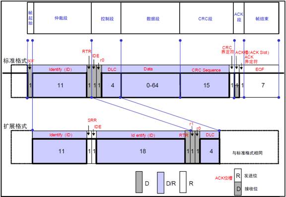
As shown in the above figure, the data frame includes:
(1) Frame start. A segment that represents the beginning of a data frame.
(2) Arbitration segment. A segment that represents the priority of the frame.
(3) Control segment. A segment that represents the number of bytes and reserved bits of data.
(4) Data segment. The content of data. 0 ~ 8 bytes of data can be sent in a frame.
(5) CRC segment. A segment that checks for frame transmission errors.
(6) ACK segment. Indicates the segment that confirms normal reception.
(7) End of frame. A segment that represents the end of a data frame.
For details, see "can2 0A”,”CAN2. "0b" details.
We mainly focus on several paragraphs that we need to pay attention to in programming:
ID: CAN message ID;
IDE: 0 is the standard frame and 1 is the extended frame;
RTR: 0 is the data frame and 1 is the remote frame;
DLC: CAN message data length, range 0 ~ 8 bytes;
Data: data, 0 ~ 8 bytes;
13.2 CAN programming framework creation
At present, what we are learning is application programming. In order to make the CAN programming framework universal and portable in the future, we create an abstract CAN application programming framework, which CAN be applied to MCU application programming or linux application programming.
Therefore, according to the general properties of CAN bus programming, we abstract the following properties:
attribute | Attribute description | explain |
|---|---|---|
CAN port number | Describe CAN ports, such as CAN1, CAN2 and CAN3, which are related to specific hardware peripherals. | |
CAN transceiver configuration | Describe CAN transceiver mode settings. Transceiver modes include Normal, Stanley, Sleep, ListenOnly and other modes; The transceiver used in this section is the default hardware configuration, so it does not need to be configured. | |
CAN controller configuration | Describe CAN transceiver configuration, such as CAN baud rate configuration, sampling rate setting, filter setting, etc; | |
CAN interrupt configuration | Describe CAN interrupt receiving function configuration | |
Read CAN message | Describe the implementation of CAN read message | |
Send CAN message | Describe the implementation of CAN sending message |
According to the attributes described in the above table, the CAN application programming framework is created as follows:
typedef struct _CAN_COMM_STRUCT
{
    /* CAN Hardware name */
    char name[10];
    /* CAN Port number, which is the port number in the bare metal machine; Socket socket interface in linux Application */
    int  can_port;
    /* CAN The controller configuration function returns the port number assigned to can_port */
    int  (*can_set_controller)( void );
    /* CAN Create an interface interrupt, and create a receiving thread in linux */
    void (*can_set_interrput)( int can_port , pCanInterrupt callback );
    /* CAN Read message interface */
    void (*can_read)( int can_port , CanRxMsg* recv_msg);
    /* CAN Send message interface*/
    void (*can_write)( int can_port , CanTxMsg send_msg);
}CAN_COMM_STRUCT, *pCAN_COMM_STRUCT;
This framework can be applied to MCU by analogy, and can also be used in Linux socket can application programming.
13.3 STM32 CAN Application Programming
This section mainly uses the application programming framework in 14.2 to test the feasibility of the framework on the single chip microcomputer, and explains it with a basic case of receiving and sending;
13.3.1 STM32 CAN interface circuit
As shown in the figure below, it is the development board STM32 minimum system and CAN transceiver interface circuit used by STM32 routine in this chapter.
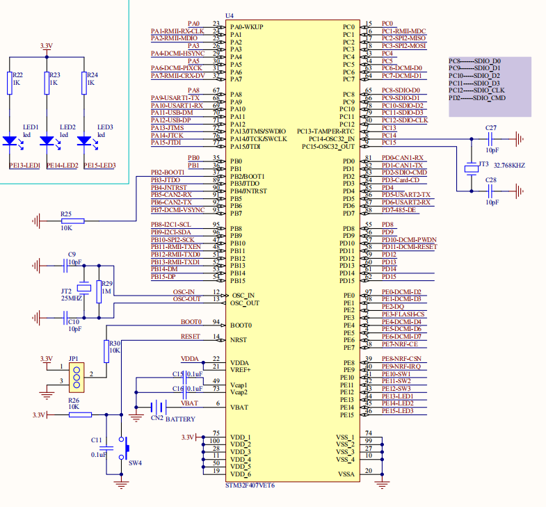
Figure 13.3 1-1 stm32f407 minimum system
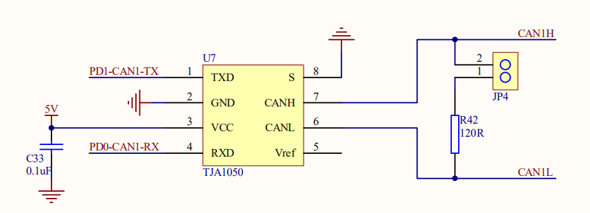
Figure 13.3 1-1 tja1050 can transceiver interface circuit
13.3.2 STM32 CAN application programming steps
Next, we implement can application programming based on STM32 step by step according to the programming framework of CAN communication.
STM32 CAN application programming, the steps are as follows:
13.3. 2.1 preparation of STM32 engineering template
See code "01_stm32f407_can" routine in Chapter 14;
The development environment used is MDK 5.24
After opening the MDK project, see the following figure:
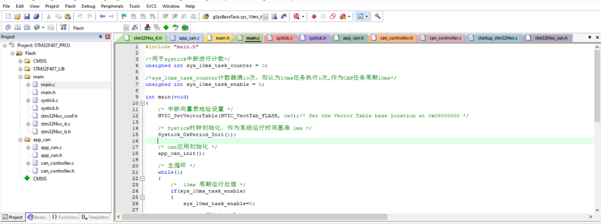
The directory in the above figure is CMSIS, STM32F407_LIB and main are the basic frameworks for STM32 operation.
Directory app_can is the file required for CAN application programming.
13.3. 2.2 write the implementation function of CAN abstract framework
(1) Define CAN port number
See "can_controller.h" file in code "01_stm32f407_can_addline" in Chapter 14.
Mainly according to the can of STM32 hardware, there are multiple channels, which are defined as can in turn_ PORTCAN1, CAN_ PORT_ Can2, etc. the current CAN1 can be known from "14.3.1 STM32 CAN interface circuit"
25 /* CAN Port number definition*/
26 enum
27 {
28     CAN_PORT_NONE = 0,
29     CAN_PORT_CAN1,
30     CAN_PORT_CAN2,
31     CAN_PORT_MAX
32 };
(2) Configure CAN controller
The configuration of CAN controller has three parts: GPIO(CAN_TX,CAN_RX pin) configuration, can baud rate configuration and can filter configuration.
See "can_controller.c" file int can in code "01_stm32f407_can_addline" in Chapter 14_ Set_ Controller (void) function.
A.GPIO(CAN_TX,CAN_RX pin) configuration
The configuration GPIO code is as follows:
96     /*************************************************************/
97     /*CAN Relevant GPIO configuration, here is: CAN_TX, CAN_RX*/
98
99     /*Enable GPIO clock*/
100     RCC_AHB1PeriphClockCmd(RCC_AHB1Periph_GPIOD, ENABLE);
101     /*Initialize pin configuration*/
102     GPIO_InitStructure.GPIO_Pin     = GPIO_Pin_0 ;
103     GPIO_InitStructure.GPIO_Mode    = GPIO_Mode_AF;
104     GPIO_InitStructure.GPIO_Speed   = GPIO_Speed_50MHz;
105     GPIO_InitStructure.GPIO_OType   = GPIO_OType_PP;
106     GPIO_InitStructure.GPIO_PuPd    = GPIO_PuPd_UP;
107     GPIO_Init(GPIOD, &GPIO_InitStructure);
108
109     GPIO_InitStructure.GPIO_Pin     = GPIO_Pin_1;
110     GPIO_InitStructure.GPIO_Mode    = GPIO_Mode_AF;
111     GPIO_InitStructure.GPIO_Speed   = GPIO_Speed_50MHz;
112     GPIO_InitStructure.GPIO_OType   = GPIO_OType_PP;
113     GPIO_InitStructure.GPIO_PuPd    = GPIO_PuPd_UP;
114     GPIO_Init(GPIOD, &GPIO_InitStructure);
115     /*Set GPIO to CAN multiplexing mode*/
116     GPIO_PinAFConfig(GPIOD, GPIO_PinSource0, GPIO_AF_CAN1);
117     GPIO_PinAFConfig(GPIOD, GPIO_PinSource1, GPIO_AF_CAN1);
B. Configure baud rate and working mode
According to the following code, enable the CAN peripheral, set the CAN working mode to Normal, and set the baud rate to 500kbps.
119     /*************************************************************/
120     /*CAN Related configuration of controller, baud rate, sampling rate, etc*/
121
122     /* Enable CAN clock */
123     RCC_APB1PeriphClockCmd(RCC_APB1Periph_CAN1, ENABLE);
124
125     /* Initialize CAN controller operating mode*/
126     CAN_DeInit(CAN1);
127     CAN_StructInit(&CAN_InitStructure);
128     CAN_InitStructure.CAN_TTCM = DISABLE;
129     CAN_InitStructure.CAN_ABOM = DISABLE;
130     CAN_InitStructure.CAN_AWUM = DISABLE;
131     CAN_InitStructure.CAN_NART = DISABLE;
132     CAN_InitStructure.CAN_RFLM = DISABLE;
133     CAN_InitStructure.CAN_TXFP = DISABLE;
134     CAN_InitStructure.CAN_Mode = CAN_Mode_Normal;//CAN operating mode
135
136     /* Initialize CAN baud rate */
137     CAN_Baud_Process(500,&CAN_InitStructure);
138     CAN_Init(CAN1, &CAN_InitStructure);
The function of configuring baud rate is a user-defined function, which can not be understood here. You only need to know that it is configuring baud rate. If you need to use the code in this chapter, you can view the specific source code project.
C. Configure CAN filter
The following code configures the filter:
141     /*************************************************************/
142     /* Initialize CAN filter */
143     CAN_FilterInitStructure.CAN_FilterNumber = 0;                       /* CAN1 Filter numbers range from 0 to 13 */
144     CAN_FilterInitStructure.CAN_FilterMode = CAN_FilterMode_IdMask;     /* Filter shielding mode */
145     CAN_FilterInitStructure.CAN_FilterScale = CAN_FilterScale_32bit;
146     CAN_FilterInitStructure.CAN_FilterIdHigh = 0x0000;
147     CAN_FilterInitStructure.CAN_FilterIdLow = 0x0000;
148     CAN_FilterInitStructure.CAN_FilterMaskIdHigh = 0x0000;      /* No ID is masked */
149     CAN_FilterInitStructure.CAN_FilterMaskIdLow = 0x0000;           /* No ID is masked */
150     CAN_FilterInitStructure.CAN_FilterFIFOAssignment = 0;
151
152     CAN_FilterInitStructure.CAN_FilterActivation = ENABLE;
153     CAN_FilterInit(&CAN_FilterInitStructure);
154
155     /*************************************************************/
156     /* After setting the CAN, return to the port number of the currently set CAN, which is mainly similar to the socket interface in Linux socket CAN */
Here we set the filter not to shield any message ID. here we just understand some processes under the single chip microcomputer.
(3) Configure CAN receive interrupt
CAN bus supports sending interrupt and receiving interrupt. Only receiving interrupt is used here.
See "can_controller.c" file void can in code "01_stm32f407_can_addline" in Chapter 14_ Set_ Interrupt (int can_port, pcaninterrupt callback) function.
CAN interrupt configuration code is as follows:
163 /**********************************************************************
164 * Function name: void CAN_Set_Interrupt(int can_port,  pCanInterrupt callback)
165 * Function Description: enable CAN interrupt processing and transfer it to the callback function of the application. The callback function mainly deals with the functions of the application layer
166 * Input parameter: can_port, port number
167 *            callback:  The callback function that interrupts the specific processing application function
168 * Output parameters: None
169 * Return value: None
170 * Modification date version number modified by
171 * -----------------------------------------------
172 * 2020/05/13         V1.0             bert            establish
173 ***********************************************************************/
174 void CAN_Set_Interrupt(int can_port,  pCanInterrupt callback)
175 {
176     NVIC_InitTypeDef NVIC_InitStructure;
177
178     /* Configure the interrupt according to the CAN port number */
179     switch( can_port )
180     {
181         case CAN_PORT_CAN1:
182         {
183             /* Initialize callback interface function */
184             if ( NULL != callback )
185             {
186                 g_pCanInterrupt = callback;
187             }
188
189             /* Use CAN0_RX interrupt is similar to creating a receiving thread in linux socket can */
190             NVIC_InitStructure.NVIC_IRQChannel = CAN1_RX0_IRQn;
191             NVIC_PriorityGroupConfig(NVIC_PriorityGroup_4);
192             NVIC_InitStructure.NVIC_IRQChannelPreemptionPriority = 0;
193             NVIC_InitStructure.NVIC_IRQChannelSubPriority = 0;
194             NVIC_InitStructure.NVIC_IRQChannelCmd = ENABLE;
195             NVIC_Init(&NVIC_InitStructure);
196             CAN_ITConfig(CAN1, CAN_IT_FMP0, ENABLE);
197         }
198         break;
199
200         default:
201             break;
202
203     }
204     return ;
205 }
CAN receive interrupt function is as follows:
275 /**********************************************************************
276 * Function name: void CAN1_RX0_IRQHandler(void)
277 * Function Description: CAN receive interrupt function
278 * Input parameters: None
279 * Output parameters: None
280 * Return value: None
281 * Modification date version number modified by
282 * -----------------------------------------------
283 * 2020/05/13         V1.0             bert            establish
284 ***********************************************************************/
285 void CAN1_RX0_IRQHandler(void)
286 {
287     /* If the callback function exists, the callback function is executed */
288     if( g_pCanInterrupt != NULL)
289     {
290         g_pCanInterrupt();
291     }
292
293     /* Clear pending interrupt */
294     CAN_ClearITPendingBit(CAN1,CAN_IT_FMP0);
295 }
Here CAN interrupt through callback function G_ The pcaninterrupt() function layers the code required by the application layer to the application layer. Here is the general interface of the driving part.
(4) CAN message reading function
When the CAN receiving interrupt is generated, read the received CAN message from FIFO through the CAN message reading function.
See "can_controller.c" file void can in code "01_stm32f407_can_addline" in Chapter 14_ Read (int can_port, canrxmsg * recv_msg) function.
CAN message reading function is as follows:
208 /**********************************************************************
209 * Function name: void CAN_Read(int can_port, CanRxMsg* recv_msg)
210 * Function Description: CAN reads the receiving register and takes out the received message
211 * Input parameter: can_port, port number
212 * Output parameter: recv_msg: receive message
213 * Return value: None
214 * Modification date version number modified by
215 * -----------------------------------------------
216 * 2020/05/13         V1.0             bert            establish
217 ***********************************************************************/
218 void CAN_Read(int can_port, CanRxMsg* recv_msg)
219 {
220     switch( can_port )
221     {
222         case CAN_PORT_CAN1:
223         {
224             /* Read CAN message from FIFO */
225             CAN_Receive(CAN1,CAN_FIFO0, recv_msg);
226         }
227         break;
228
229         default:
230             break;
231     }
232     return ;
233 }
(5) CAN message sending function
When it is necessary to send CAN message, start sending message by sending mailbox filling data to CAN.
See "can_controller.c" file void can in code "01_stm32f407_can_addline" in Chapter 14_ Write (int can_port, cantxmsg send_msg) function.
CAN message reading function is as follows:
235 /**********************************************************************
236 * Function name: void CAN_Write(int can_port, CanTxMsg send_msg)
237 * Function Description: CAN message sending interface, call sending register to send message
238 * Input parameter: can_port, port number
239 * Output parameter: send_msg: send message
240 * Return value: None
241 * Modification date version number modified by
242 * -----------------------------------------------
243 * 2020/05/13         V1.0             bert            establish
244 ***********************************************************************/
245 void CAN_Write(int can_port, CanTxMsg send_msg)
246 {
247     unsigned char i;
248     uint8_t transmit_mailbox = 0;
249     CanTxMsg TxMessage;
250
251     switch( can_port )
252     {
253         case CAN_PORT_CAN1:
254         {
255             TxMessage.StdId = send_msg.StdId;     // The standard identifier is 0x000~0x7FF
256             TxMessage.ExtId = 0x0000;             // Extension identifier 0x0000
257             TxMessage.IDE   = CAN_ID_STD;         // Use standard identifier
258             TxMessage.RTR   = CAN_RTR_DATA;       // Set as data frame
259             TxMessage.DLC   = send_msg.DLC;       // Data length: the maximum data length specified in can message is 8 bytes
260
261             for(i=0; i<TxMessage.DLC; i++)
262             {
263                 TxMessage.Data[i] = send_msg.Data[i];
264             }
265             transmit_mailbox = CAN_Transmit(CAN1,&TxMessage);  /* Return the mailbox number 0,1,2 of this information request or no mailbox request to send no_box */
266         }
267         break;
268
269         default:
270             break;
271     }
272     return ;
273 }
(6) CAN abstract structure framework initialization
Define a Can1 communication structure instance CAN_COMM_STRUCT can1_controller;
Using the functions implemented in steps (1) ~ (5), initialize can1_controller to form a connection point associated with the application layer.
298 /**********************************************************************
299 * Name: can1_controller
300 * Function Description: CAN1 structure initialization
301 * Modification date version number modified by
302 * -----------------------------------------------
303 * 2020/05/13         V1.0             bert            establish
304 ***********************************************************************/
305 CAN_COMM_STRUCT can1_controller = {
306     .name                   = "can0",
307     .can_port               = CAN_PORT_CAN1,
308     .can_set_controller     = CAN_Set_Controller,
309     .can_set_interrput      = CAN_Set_Interrupt,
310     .can_read               = CAN_Read,
311     .can_write              = CAN_Write,
312 };
13.3. 2.3 writing CAN application layer code
According to 14.3 2.2 the specific CAN hardware operation has been realized, and the CAN programming framework has been abstractly instantiated.
But we haven't connected to the application layer yet. The application layer doesn't know which interface to call.
(1) CAN application layer registration instance
Write a general instantiation registration function in the application layer.
See "app_can.c" file int register in code "01_stm32f407_can_addline" in Chapter 14_ can_ Controller (const pcan_comm_struct p_can_controller) function.
The code implementation is as follows:
62 /**********************************************************************
63 * Function name: int register_can_controller(const pCAN_COMM_STRUCT p_can_controller)
64 * Function Description: the application layer registers CAN1 structure
65 * Input parameter: p_can_controller, abstract structure of CAN controller
66 * Output parameters: None
67 * Return value: None
68 * Modification date version number modified by
69 * -----------------------------------------------
70 * 2020/05/13         V1.0             bert            establish
71 ***********************************************************************/
72 int register_can_controller(const pCAN_COMM_STRUCT p_can_controller)
73 {
74     /* Judge incoming p_ can_ The controller is non empty to confirm that the structure is an entity*/
75     if( p_can_controller != NULL )
76     {
77         /* The passed in parameter p_ can_ The controller is assigned to the application layer structure gCAN_COMM_STRUCT */
78
79         /*Port number, analog socket can socket*/
80         gCAN_COMM_STRUCT.can_port              = p_can_controller->can_port;
81         /*CAN Controller configuration function*/
82         gCAN_COMM_STRUCT.can_set_controller    = p_can_controller->can_set_controller;
83         /*CAN Interrupt configuration*/
84         gCAN_COMM_STRUCT.can_set_interrput     = p_can_controller->can_set_interrput;
85         /*CAN Message reading function*/
86         gCAN_COMM_STRUCT.can_read              = p_can_controller->can_read;
87         /*CAN Message sending function*/
88         gCAN_COMM_STRUCT.can_write             = p_can_controller->can_write;
89         return 1;
90     }
91      return 0;
92 }
Then by calling register_ can_ controller( &can1_controller ); Set instance Can1_ The controller is registered with the 4 static can of the application_ COMM_ STRUCT gCAN_ COMM_ STRUCT;
After that, the application layer only needs to call its own gcan_ COMM_ The structure instance CAN operate the CAN communication function.
315 /**********************************************************************
316 * Function name: void CAN1_contoller_add(void)
317 * Function Description: CAN structure registration interface. CAN1 is used in the application layer_ Controller prior call
318 * Input parameters: None
319 * Output parameters: None
320 * Return value: None
321 * Modification date version number modified by
322 * -----------------------------------------------
323 * 2020/05/13         V1.0             bert            establish
324 ***********************************************************************/
325 void CAN1_contoller_add(void)
326 {
327     /*Set Can1_ The controller is passed to the application layer*/
328     register_can_controller( &can1_controller );
329 }
(2) CAN application layer initialization
CAN application layer initialization code is as follows:;
94 /**********************************************************************
95 * Function name: void app_can_init(void)
96 * Function Description: CAN application layer initialization
97 * Input parameters: None
98 * Output parameters: None
99 * Return value: None
100 * Modification date version number modified by
101 * -----------------------------------------------
102 * 2020/05/13         V1.0             bert            establish
103 ***********************************************************************/
104 void app_can_init(void)
105 {
106     /**
107     * Application layer for CAN1 structure registration
108     */
109     CAN1_contoller_add();
110
111     /*
112     *Call can_ set_ The controller configures the CAN controller,
113     *Return to can_port, similar to the socket interface in linux socketcan, it is used as a custom CAN channel in the MCU routine
114     */
115     gCAN_COMM_STRUCT.can_port = gCAN_COMM_STRUCT.can_set_controller();
116     /**
117     * Call can_set_interrput configures the CAN receiving interrupt, which is similar to the receiving thread in socketcan
118     */
119     gCAN_COMM_STRUCT.can_set_interrput( gCAN_COMM_STRUCT.can_port, CAN_RX_IRQHandler_Callback );
120 }
(3) Design a simple periodic message sending function
The function code of CAN periodic sending message is realized as follows:
123 /**********************************************************************
124 * Function name: void app_can_tx_test(void)
125 * Function Description: CAN application layer message sending function, which is used to send messages in test cycle
126 * Input parameters: None
127 * Output parameters: None
128 * Return value: None
129 * Modification date version number modified by
130 * -----------------------------------------------
131 * 2020/05/13         V1.0             bert            establish
132 ***********************************************************************/
133 void app_can_tx_test(void)
134 {
135     // Run the CAN test program based on 10ms
136
137     unsigned char i=0;
138
139     /* Send message definition */
140     CanTxMsg TxMessage;
141
142     /* A byte is used as a counter in the sent message */
143     static unsigned char tx_counter = 0;
144
145     /* Taking 10ms as the benchmark, set the period of running code after the processing function to 1 second through the timer counter*/
146     static unsigned int timer =0;
147     if(timer++>100)
148     {
149         timer = 0;
150     }
151     else
152     {
153         return ;
154     }
155
156     /* Send message data filling, and the message cycle is 1 second */
157     TxMessage.StdId = TX_CAN_ID;          /* The standard identifier is 0x000~0x7FF */
158     TxMessage.ExtId = 0x0000;             /* Extension identifier 0x0000 */
159     TxMessage.IDE   = CAN_ID_STD;         /* Use standard identifier */
160     TxMessage.RTR   = CAN_RTR_DATA;       /* Set as data frame  */
161     TxMessage.DLC   = 8;                  /* Data length: the maximum data length specified in can message is 8 bytes */
162
163     /* Fill data, which can be filled according to the actual application */
164     TxMessage.Data[0] = tx_counter++;       /* Counter used to identify message sending */
165     for(i=1; i<TxMessage.DLC; i++)
166     {
167         TxMessage.Data[i] = i;
168     }
169
170     /*  Call can_write send CAN message */
171     gCAN_COMM_STRUCT.can_write(gCAN_COMM_STRUCT.can_port, TxMessage);
172
173 }
(4) Design a simple message receiving function
220 /**********************************************************************
221 * Function name: void CAN_RX_IRQHandler_Callback(void)
222 * Function Description: CAN1 receive interrupt function; In linux, you CAN use threads or timers to read CAN data
223 * Input parameters: None
224 * Output parameters: None
225 * Return value: None
226 * Modification date version number modified by
227 * -----------------------------------------------
228 * 2020/05/13         V1.0             bert            establish
229 ***********************************************************************/
230 void CAN_RX_IRQHandler_Callback(void)
231 {
232     /* Definition of received message */
233     CanRxMsg RxMessage;
234
235     /* Reset received message */
236     memset( &RxMessage, 0, sizeof(CanRxMsg) );
237
238     /* Via can_ The read interface reads the message received by the register */
239     gCAN_COMM_STRUCT.can_read(gCAN_COMM_STRUCT.can_port, &RxMessage);
240
241     /* Copy the read can message to the global message structure g_CAN1_Rx_Message */
242     memcpy(&g_CAN1_Rx_Message, &RxMessage, sizeof( CanRxMsg ) );
243
244     /* Set the current reception completion flag and judge that the current received message ID is RX_CAN_ID, set g_CAN1_Rx_Flag=1*/
245     if( g_CAN1_Rx_Message.StdId == RX_CAN_ID )
246     {
247         g_CAN1_Rx_Flag = 1;
248     }
249 }
176 /**********************************************************************
177 * Function name: void app_can_rx_test(void)
178 * Function Description: the CAN application layer receives the message processing function, which is used to process the message received in the interrupt function
179 * Input parameters: None
180 * Output parameters: None
181 * Return value: None
182 * Modification date version number modified by
183 * -----------------------------------------------
184 * 2020/05/13 V1.0 bert establish
185 ***********************************************************************/
186 void app_can_rx_test(void)
187 {
188 unsigned char i=0;
189
190 /* Send message definition */
191 CanTxMsg TxMessage;
192
193 /* A byte is used as a counter in the sent message */
194 static unsigned char rx_counter = 0;
195
196
197 if( g_CAN1_Rx_Flag == 1)
198 {
199 g_CAN1_Rx_Flag = 0;
200
201 /* Send message data filling, and the message cycle is 1 second */
202 TxMessage.StdId = RX_TO_TX_CAN_ID; /* The standard identifier is 0x000~0x7FF */
203 TxMessage.ExtId = 0x0000; /* Extension identifier 0x0000 */
204 TxMessage.IDE = CAN_ID_STD; /* Use standard identifier */
205 TxMessage.RTR = CAN_RTR_DATA; /* Set as data frame */
206 TxMessage.DLC = 8; /* Data length: the maximum data length specified in can message is 8 bytes */
207
208 /* Fill data, which can be filled according to the actual application */
209 TxMessage.Data[0] = rx_counter++; /* Counter used to identify message sending */
210 for(i=1; i<TxMessage.DLC; i++)
211 {
212 TxMessage.Data[i] = g_CAN1_Rx_Message.Data[i];
213 }
214
215 /* Call can_write send CAN message */
216 gCAN_COMM_STRUCT.can_write(gCAN_COMM_STRUCT.can_port, TxMessage);
217 }
218 }13.3.2.4 STM32 CAN case test
After writing the code in the previous chapters, let's do a test;
The test tools are Valuecan3(CAN protocol box) and Vehicle Vspy3 (computer software) of interbest.
You CAN also buy a cheap USB to CAN tool on Taobao.
The test steps are as follows:
Step 1: download the completed STM32 CAN test program to the actual development board;
Step 2: Send a message with message ID 0X201 through CAN test tool Vehicle Vspy3;
Step 3: observe the CAN test software display as follows:
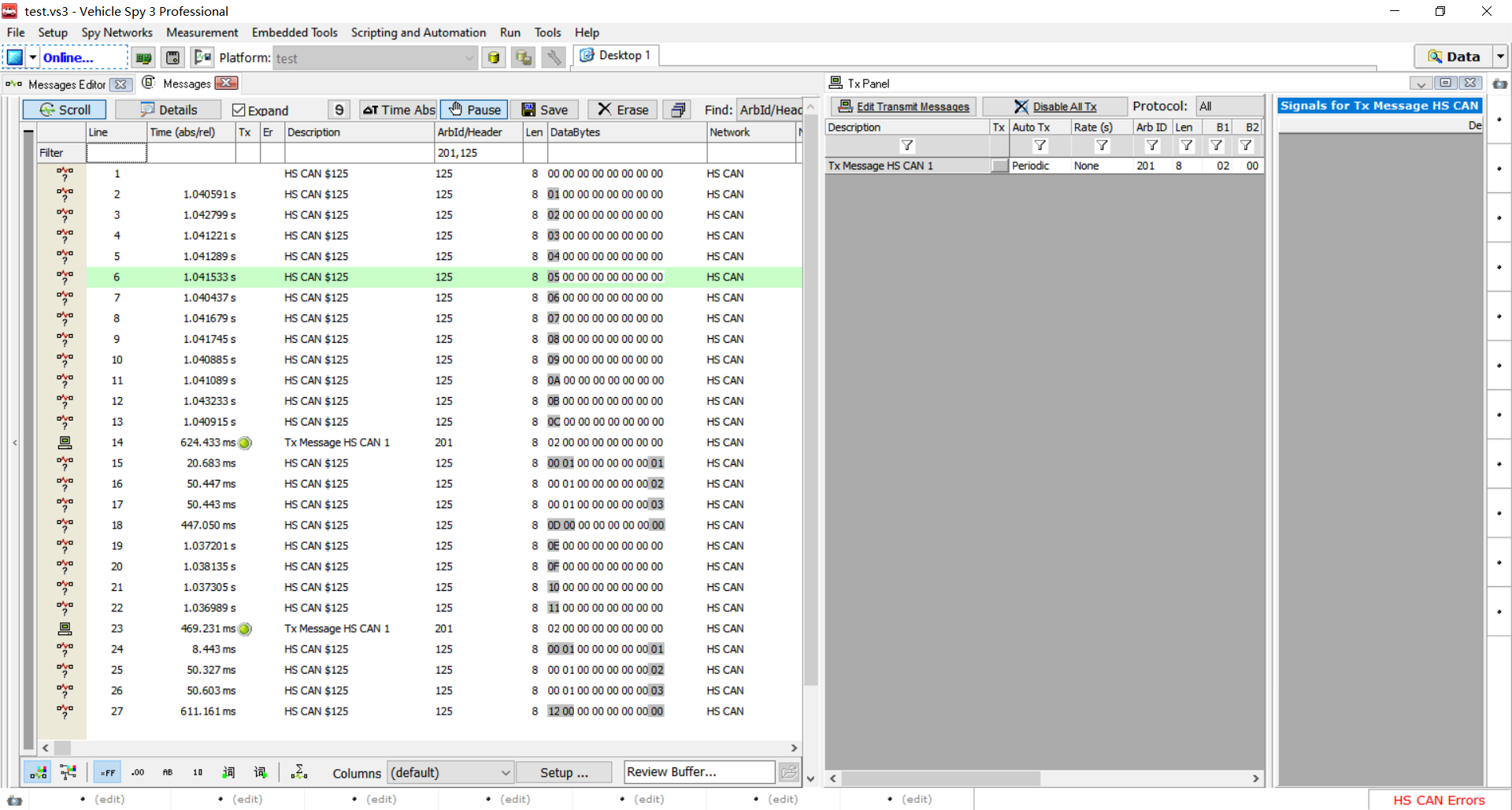
The message with message ID 0x101 is sent according to 1-second cycle, as shown in Figure 14.3 2.4-1.
The message with message ID 0x201 is sent by Vehicle Spy3 to STM32 development board according to the cycle of 500ms, as shown in Figure 14.3 2.4-1
The message with message ID 0x301 is transferred to the message with message ID 0x301 after receiving the message with message ID 0x201, as shown in Figure 14.3 2.4-2.
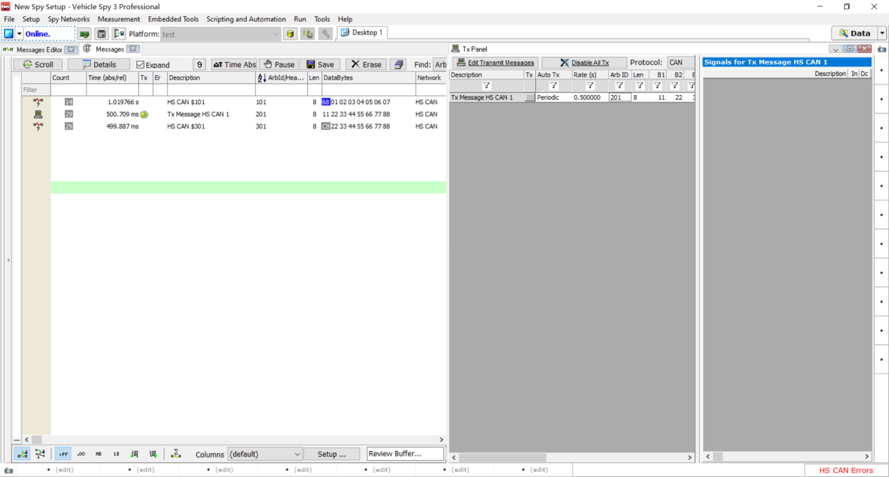
Figure 13.3 2.4-1 message sending result viewing
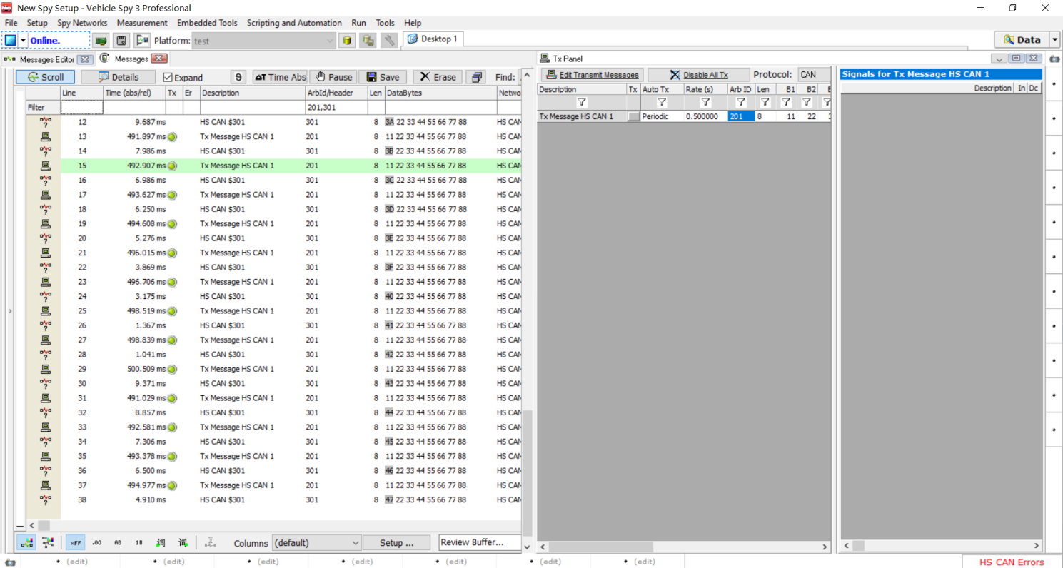
Figure 13.3 2.4-2 viewing message reception
13.4 basic application programming of Linux socketcan
13.4.1 socketcan overview
socketcan is an implementation method of CAN protocol (Controller Area Network) under Linux. Can is a network technology widely used in the fields of automatic control, embedded equipment and automobile all over the world. The earliest method of using can under Linux is based on character device. The difference is that Socket CAN uses Berkeley's socket interface and Linux network protocol stack. This method enables can device driver to call through network interface. The Socket CAN interface is designed to be as close to the TCP/IP protocol as possible, so that programmers familiar with network programming can learn and use it easily.
The main purpose of using Socket CAN is to provide socket interface based on Linux network layer for user space applications. Different from the well-known TCP/IP protocol and Ethernet, can bus has no MAC layer address similar to Ethernet and can only be used for broadcasting. CAN ID is only used for bus arbitration. Therefore, the CAN ID must be unique on the bus. When designing a CAN-ECU(Electronic Control Unit) network, the can message ID can be mapped to a specific ECU. Therefore, the can message ID can be used as the address of the sending source.
13.4. 2. Basic knowledge of socketcan
In "14.3 STM32 CAN Application Programming", we have completely constructed the CAN application programming framework. However, in linux application programming, the idea of operating the CAN underlying driver is similar to that of STM32, but the operation methods or called interfaces are still very different, because STM32 is an SDK package or register directly called, However, linux system needs to call system commands or linux CAN driver to realize the operation of the physical layer.
Therefore, here we focus on some system call commands on linux and some concepts related to socket can.
13.4.2.1 CAN equipment operation
CAN equipment has three functions: on, off and parameter setting. Because the CAN device under linux is a way to simulate network operation, the opening, closing and setting of the CAN device here are operated through ip commands.
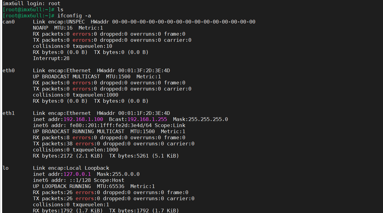
At 100ask_ Open the serial port on the imx6ull development board and use "ifconfig -a" to view all network nodes. It is found that the first node is "can0".
(1) Linux CAN device on:
#define ip_ cmd_ Open "ifconfig CAN0 up" / * open CAN0*/
Description: can0: can device name;
up: open device command
(2) Linux CAN device shutdown:
#define ip_ cmd_ Close "ifconfig CAN0 down" / * close CAN0*/
Description: can0: can device name;
down: shutdown device command
(2) Linux CAN parameter settings (baud rate, sampling rate):
#define ip_cmd_set_can_params "ip link set can0 type can bitrate 500000 triple-sampling on"

/* Set CAN0 baud rate to 500000 bps */
Description: can0: can device name;
down: shutdown device command
Type can: the device type is can
Bitrate 500000: baud rate is set to 500kbps
Triple sampling on: sampling on
13.4. 2.2 what is Socket socket interface
In linux, the network operation uses socket to create the interface. Unexpectedly, the CAN device is also a virtual network interface and a socket socket interface.
As shown in the figure below, telephone A calls telephone b, telephone A will enter the number of telephone b, and telephone B will receive an incoming call from telephone A.
Phone A and phone B are two endpoints. The linux socket interface is similar to this telephone communication. The socket interface is A communication endpoint, and there is A communication link between the endpoints; Telephone communication is dial-up communication through telephone number, and socket interface uses address to identify each other.

Figure 13.2 2.2 telephone communication model
13.4.2.3 Socket interface function
If we want to create and use socket sockets for communication programming, we need to understand the socket related interface functions.
If you need to query the functions in the linux system, you can view them through the man command.
give an example:
man socket / * view socket function description*/
(1) socket() function
Under linux system, query socket() function through "man socket" command is described as follows:
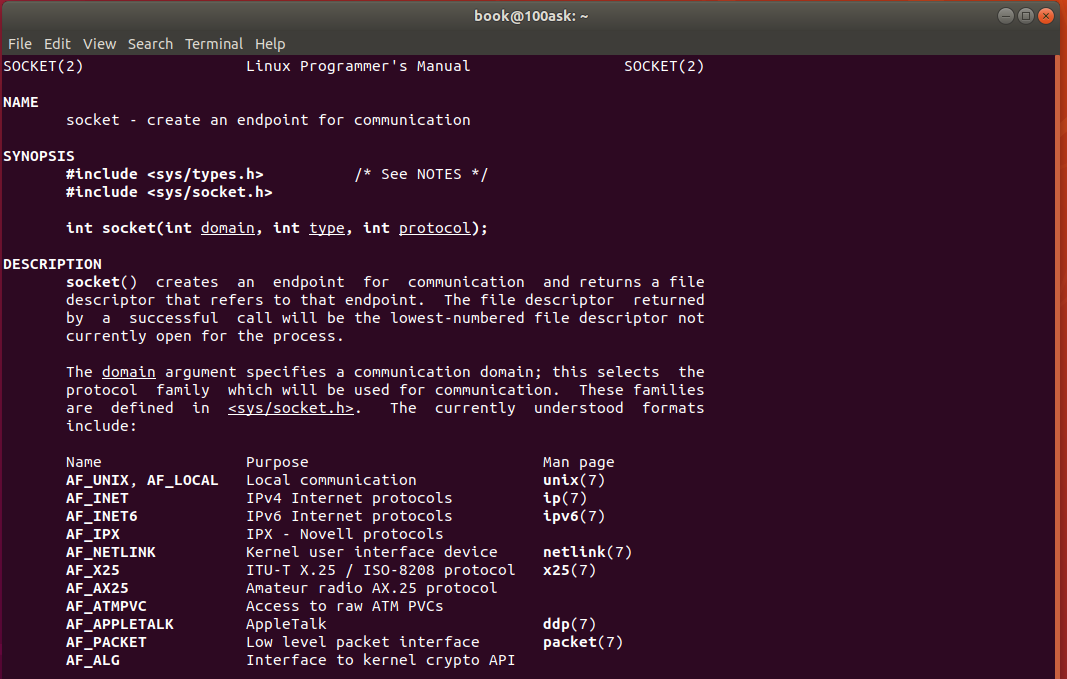
The prototype of Socket function is as follows:
#include <sys/types.h>

#include <sys/socket.h>

int socket(int domain, int type, int protocol);  /* Socket function prototype */
The three parameters of the function are as follows:
Domain: protocol domain, It is also called protocol family. The commonly used protocol families include AF_INET, AF_INET6, AF_LOCAL (or AF_UNIX, Unix domain socket), AF_ROUTE, etc. the protocol family determines the address type of socket, and the corresponding address must be used in communication. For example, AF_INET determines the ipv4 address (32-bit) and port number to be used The combination of (16 bit), AF_UNIX determines to use an absolute pathname as the address. |
|---|
Type: Specifies the socket type. The commonly used socket types are SOCK_STREAM,SOCK_DGRAM,SOCK_RAW,SOCK_PACKET,SOCK_SEQPACKET, etc. |
Protocol: Specifies the protocol. Commonly used protocols are IPPROTO_TCP,IPPTOTO_UDP,IPPROTO_SCTP,IPPROTO_TIPC, etc., which correspond to TCP transmission protocol, UDP transmission protocol, STCP transmission protocol and TIPC transmission protocol respectively. |
be careful:
1. The above type and protocol can not be combined at will, such as SOCK_STREAM cannot be associated with IPPROTO_UDP combination. When the protocol is 0, the default protocol corresponding to the type will be automatically selected.
When we call socket to create a socket, the returned socket descriptor exists in the address family (AF_XXX) space, but does not have a specific address. If you want to assign an address to it, you must call the bind() function. Otherwise, when you call connect() and listen(), the system will automatically assign a port at random.
2. The domain protocol domain used by socketcan is AF_ Can (or PF_CAN), type is SOCK_RAW, specifies that the protocol is CAN_RAW.
(2) bind() function
Under linux system, query the bind() function through the "man bind" command. The description is as follows:
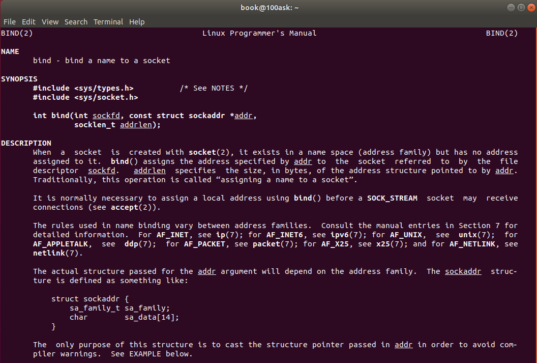
The bind() function assigns a specific address in an address family to the socket. For example, corresponding to AF_INET,AF_INET6 is to assign an ipv4 or ipv6 address and port number combination to the socket.
The Bind function prototype is as follows:
#include <sys/types.h>
#include <sys/socket.h>
int bind(int sockfd, const struct sockaddr *addr,socklen_t addrlen);
The three parameters of the function are:
sockfd: socket descriptor, which is created by socket() function and uniquely identifies a socket. The bind() function is to bind a name to this descriptor.
addr: a const struct sockaddr * pointer to the protocol address to be bound to sockfd. The address structure is different according to the address protocol family when creating the socket,
For example, ipv4 corresponds to:
struct sockaddr_in {
    sa_family_t    sin_family;   /* address family: AF_INET */
    in_port_t      sin_port;    /* port in network byte order */
    struct in_addr sin_addr;     /* internet address */
};
/* Internet address. */struct in_addr {
    uint32_t       s_addr;     /* address in network byte order */
};
ipv6 corresponds to:
struct sockaddr_in6 {
    sa_family_t     sin6_family;   /* AF_INET6 */
    in_port_t       sin6_port;     /* port number */
    uint32_t        sin6_flowinfo; /* IPv6 flow information */
    struct in6_addr  sin6_addr;     /* IPv6 address */
    uint32_t        sin6_scope_id; /* Scope ID (new in 2.4) */
};
struct in6_addr {
    unsigned char   s6_addr[16];   /* IPv6 address */
};
Unix domain corresponds to:
#define UNIX_PATH_MAX  108
struct sockaddr_un {
  sa_family_t sun_family;        /* AF_UNIX */
  char    sun_path[UNIX_PATH_MAX]; /* pathname */
};
The CAN domain corresponds to:
It is defined in the file "Linux-4.9.88\include\uapi\linux\can.h", which is the focus of this chapter.
/**
 * struct sockaddr_can - CAN sockets Address structure of
 * @can_family:  Address protocol family AF_CAN.
 * @can_ifindex:  CAN Network interface index
 * @can_addr:    Protocol address information
 */
struct sockaddr_can {
	__kernel_sa_family_t can_family;
	int         can_ifindex;
	union {
		/* Transmission protocol class address information (e.g. ISOTP) */
		struct { canid_t rx_id, tx_id; } tp;

		/* CAN protocol address information reserved for future use*/
	} can_addr;
};
addrlen: corresponds to the length of the address.
Usually, when the server starts, it will bind a well-known address (such as ip address + port number) to provide services, and the client can connect to the server through it. The client does not need to specify it. The system automatically assigns a combination of port number and its own ip address. This is why the server usually calls bind() before listen, The client will not call, but will be randomly generated by the system when connect().
(3) ioctl() function
Under linux system, query ioctl() function through "man ioctl" command. The description is as follows:
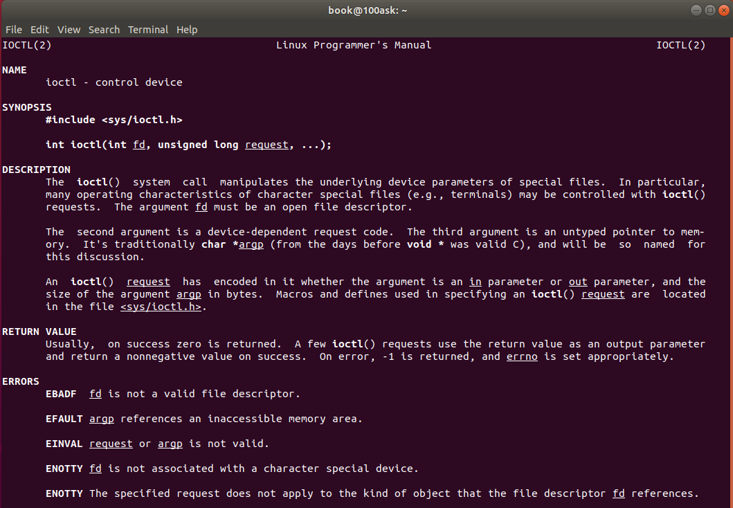
The call hierarchy of Ioctl() function is shown in the following figure:

The prototype of Ioctl() function is as follows:
#include <sys/ioctl.h>
int ioctl(int fd, unsigned long request, ...);
Two structures ifconf and ifreq are used to obtain the local network interface address with ioctl.
struct ifreq definition ifreq is used to store the information of an interface.
struct ifreq is defined in the file "Linux-4.9.88\include\uapi\linux\if.h". This only needs to be understood that it is used to obtain the CAN device index (ifr_ifindex) when ioctl() function is called. Other parameters CAN be ignored.
/*
 * Interface request structure used for socket
 * ioctl's.  All interface ioctl's must have parameter
 * definitions which begin with ifr_name.  The
 * remainder may be interface specific.
 */

/* for compatibility with glibc net/if.h */
#if __UAPI_DEF_IF_IFREQ
struct ifreq {
#define IFHWADDRLEN	6
	union
	{
		char	ifrn_name[IFNAMSIZ];		/* if name, e.g. "en0" */
	} ifr_ifrn;

	union {
		struct	sockaddr ifru_addr;
		struct	sockaddr ifru_dstaddr;
		struct	sockaddr ifru_broadaddr;
		struct	sockaddr ifru_netmask;
		struct  sockaddr ifru_hwaddr;
		short	ifru_flags;
		int	ifru_ivalue;
		int	ifru_mtu;
		struct  ifmap ifru_map;
		char	ifru_slave[IFNAMSIZ];	/* Just fits the size */
		char	ifru_newname[IFNAMSIZ];
		void __user *	ifru_data;
		struct	if_settings ifru_settings;
	} ifr_ifru;
};
#endif /* __UAPI_DEF_IF_IFREQ */

#define ifr_name	ifr_ifrn.ifrn_name	/* interface name 	*/
#define ifr_hwaddr	ifr_ifru.ifru_hwaddr	/* MAC address 		*/
#define	ifr_addr	ifr_ifru.ifru_addr	/* address		*/
#define	ifr_dstaddr	ifr_ifru.ifru_dstaddr	/* other end of p-p lnk	*/
#define	ifr_broadaddr	ifr_ifru.ifru_broadaddr	/* broadcast address	*/
#define	ifr_netmask	ifr_ifru.ifru_netmask	/* interface net mask	*/
#define	ifr_flags	ifr_ifru.ifru_flags	/* flags		*/
#define	ifr_metric	ifr_ifru.ifru_ivalue	/* metric		*/
#define	ifr_mtu		ifr_ifru.ifru_mtu	/* mtu			*/
#define ifr_map		ifr_ifru.ifru_map	/* device map		*/
#define ifr_slave	ifr_ifru.ifru_slave	/* slave device		*/
#define	ifr_data	ifr_ifru.ifru_data	/* for use by interface	*/
#define ifr_ifindex	ifr_ifru.ifru_ivalue	/* interface index	*/
#define ifr_bandwidth	ifr_ifru.ifru_ivalue    /* link bandwidth	*/
#define ifr_qlen	ifr_ifru.ifru_ivalue	/* Queue length 	*/
#define ifr_newname	ifr_ifru.ifru_newname	/* New name		*/
#define ifr_settings	ifr_ifru.ifru_settings	/* Device/proto settings*/
struct ifconf definition ifconf is usually used to save all interface information. It is not used in this chapter and will not be described in detail here.
(4) setsockopt() function
Under linux system, query setsockopt() function through "man setsockopt" command. The description is as follows:
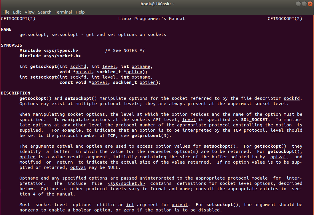
The prototypes of setsockopt() and getsockopt functions are as follows:
#include <sys/types.h>
#include <sys/socket.h>
int getsockopt(int sockfd, int level, int optname,void *optval, socklen_t *optlen);
int setsockopt(int sockfd, int level, int optname, const void *optval, socklen_t optlen);
Setsockopt() is used for any type and any state Socket interface Set option value for. Although there are options at different protocol layers, this function only defines the options at the highest "socket" level.
The function parameters are as follows:
sockfd: a descriptor that identifies a socket interface. |
|---|
Level: the level defined by the option; Support SOL_SOCKET,IPPROTO_TCP,IPPROTO_IP,IPPROTO_IPV6,SOL_CAN_RAW et al. |
optname: options to be set. |
optval: pointer to the buffer where the new value of the option to be set is stored. |
optlen: length of optval buffer. |
Examples of function calls are as follows:
Example 1: set the CAN filter to not receive all messages. |
|---|
//Disable the filtering rule. This process does not receive messages and is only responsible for sending them. / / set the filtering rule setsockopt(s, SOL_CAN_RAW, CAN_RAW_FILTER, NULL, 0); |
Example 2: set the CAN filter to receive a specified message |
|---|
//Define the receiving rule, and only receive messages with the symbol 0x201. / / it is defined in the linux header file, or you can define #define can by yourself_ SFF_ Mask 0x000007ffu / / define a filter (1) struct can_filter rfilter [1]; rfilter [0]. Can_id = 0x201; rfilter [0]. Can_mask = can_sff_mask. / / set the filter rule setsockopt (s, sol_, can_raw, can_filter, & rfilter, sizeof (rfilter)); |
Example 2: set the CAN filter to receive a specified message |
|---|
//Define the receiving rule, and only receive messages with the symbol 0x201. / / it is defined in the linux header file, or you can define #define can by yourself_ SFF_ Mask 0x000007ffu / / define filters (3): struct can_filter rfilter[3]; rfilter[0].can_id = 0x201; rfilter[0].can_mask = CAN_SFF_MASK; rfilter[1].can_id = 0x401; rfilter[1].can_mask = CAN_SFF_MASK; rfilter[2].can_id = 0x601; rfilter[2].can_mask = CAN_SFF_MASK; / / set the filter rule setsockopt (s, sol_can_raw, can_raw_filter, & rfilter, sizeof (rfilter)); |
(5) write() function
Under linux system, query the write() function through the "man 2 write" command. The description is as follows:
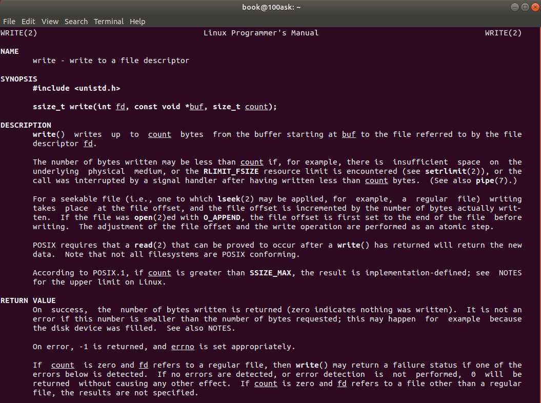
The prototype of Write function is as follows:
#include <unistd.h>
ssize_t write(int fd, const void *buf, size_t count);
(6) read() function
Under linux system, query the read() function through the "man 2 read" command. The description is as follows:
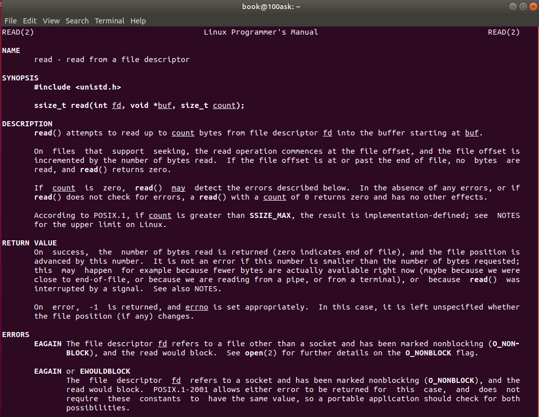
The prototype of Read function is as follows:
#include <unistd.h>
ssize_t read(int fd, void *buf, size_t count);
(7) close() function
Under linux system, query the close() function through the "man 2 close" command. The description is as follows:
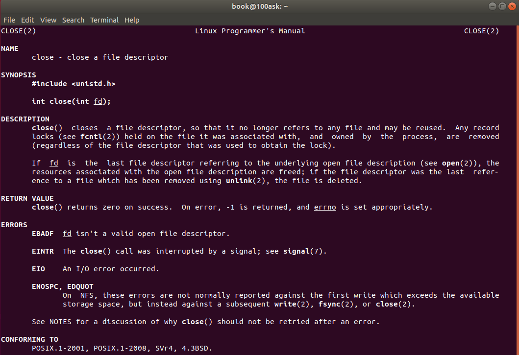
The prototype of the close() function is as follows:
#include <unistd.h>
int close(int fd);
13.4.3 socket_can simple sending example
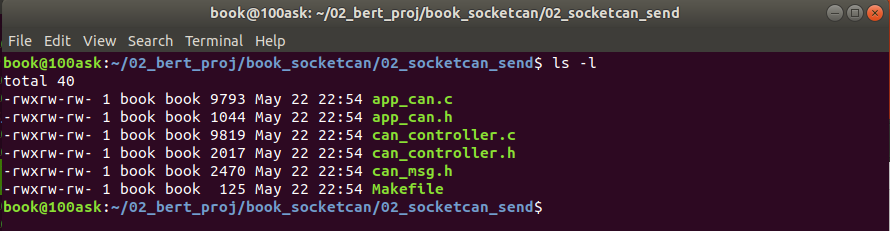
Simple send instance code directory: "02_socketcan_send"
Case description:
- Send the message with message ID: 0x101 within 1 second;
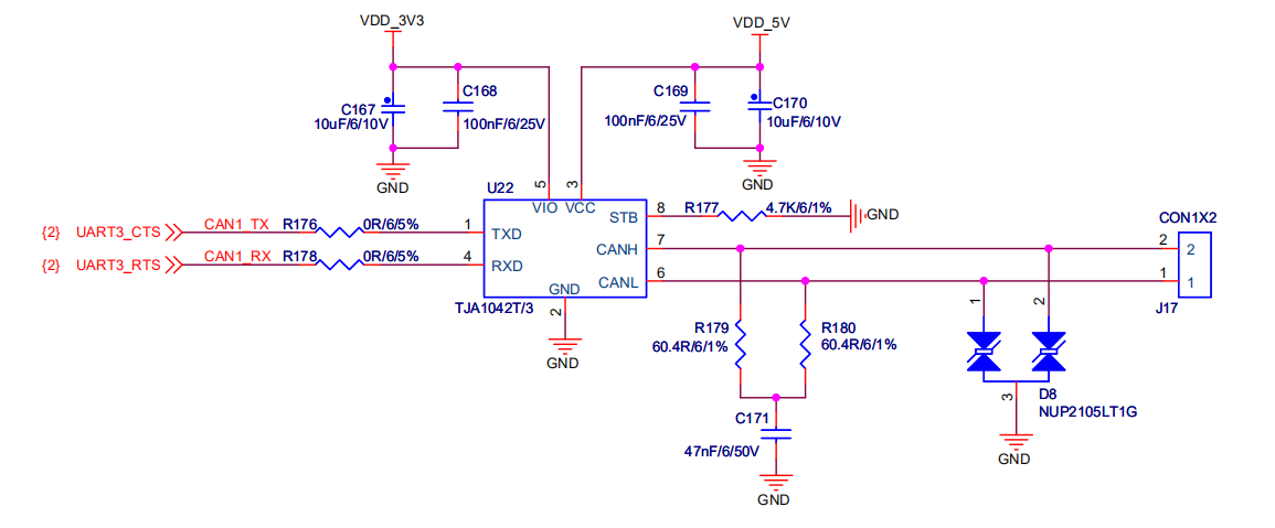
Understanding content: IMX6 CAN interface circuit
From the following CAN peripheral circuit, it is exactly the same as STM32, but it only deals with the internal CAN controller. There will be some small differences due to different chip manufacturers. The circuit here is just a comparison. linux applications do not need to pay attention to the underlying driver processing.
Now we build the framework of CAN application programming under STM32 according to chapter 14.3, and write the application programming of socket CAN under linux step by step.
preparation:
We have prepared the code file of can application according to chapter 14.3:
file name | File content description |
|---|---|
App_can.c | Realization of CAN application function |
App_can.h | CAN application function header file |
Can_controller.c | Concrete implementation of CAN drive operation abstraction layer |
Can_controller.h | CAN driver operation abstraction layer header file |
Can_msg.h | The basic structure of CAN message, copied from STM32 CAN driver, mainly uses the structure we are most familiar with when using CAN message. This file is a new file relative to STM32, because our framework is based on MCU application, and then analogically migrate to linux. |
Makefile | Makefile compilation script |
13.4. 3.1 write the implementation function of the abstract framework
First, we use the abstract structure already built in Chapter 14.3, as follows:
See "can_controller.h" in code "02_socketcan_send_addline" in Chapter 14.
34 /* CAN Communication abstract structure definition*/
35 typedef struct _CAN_COMM_STRUCT
36 {
37     /* CAN Hardware name */
38     char *name;
39     /* CAN Port number, which is the port number in the bare metal machine; Socket socket interface in linux Application */
40     int  can_port;
41     /* CAN The controller configuration function returns the port number assigned to can_port */
42     int  (*can_set_controller)( void );
43     /* CAN Create an interface interrupt, and create a receiving thread in linux */
44     void (*can_set_interrput)( int can_port , pCanInterrupt callback );
45     /* CAN Read message interface */
46     void (*can_read)( int can_port , CanRxMsg* recv_msg);
47     /* CAN Send message interface*/
48     void (*can_write)( int can_port , CanTxMsg send_msg);
49 }CAN_COMM_STRUCT, *pCAN_COMM_STRUCT;
50
We write CAN in the order of this structure_ controller. C CAN drive operation specific implementation function.
(1) Define CAN devices
According to 14.4 Chapter 2.1 describes that the linux application layer needs to know the device name to operate the CAN device
At 100ask_ Open the serial port on the imx6ull development board, use the "ifconfig -a" command to check, and know that the current CAN device name is "can0".
You CAN turn on, set up, and turn off CAN devices directly using IP commands on the linux command line. Therefore, we define three macro IPS_ cmd_ open, ip_ cmd_ close,ip_ cmd_ set_ CAN_ Params, these three macros CAN be executed through the system call system().
See the macro definition in the "can_controller.c" file in the code "02_socketcan_send_addline" in Chapter 14.
29 /**************Macro definition**************************************************/
30
31 /* Set CAN0 baud rate to 500000 bps */
32 #define ip_cmd_set_can_params  "ip link set can0 type can bitrate 500000 triple-sampling on"
33
34 /* Open CAN0 */
35 #define ip_cmd_open            "ifconfig can0 up"
36
37 /* Close CAN0 */
38 #define ip_cmd_close           "ifconfig can0 down"
(2) Configure CAN controller
There are three parts to configure CAN controller: open can0 device, CAN baud rate configuration and CAN filter configuration.
See "can_controller.c" file int can in code "01_stm32f407_can_addline" in Chapter 14_ Set_ Controller (void) function.
A. Configure baud rate and open can0 device
Use the three commands in (1) ip_cmd_open, ip_cmd_close,ip_cmd_set_can_params to call through the system: the specific code is as follows:
77     /* Set the CAN baud rate by calling the ip command through the system */
78     system(ip_cmd_close);
79     system(ip_cmd_set_can_params);
80     system(ip_cmd_open);
B. Create socket
Because linux application operating devices use read and write operations, everything in linux is a file, and socketcan is a special file, so we need to call socket() function to create a socketcan interface and obtain the socket_ FD descriptor.
The specific codes are as follows:
82   /*************************************************************/
83   /* Create socket sock_fd */
84   sock_fd = socket(AF_CAN, SOCK_RAW, CAN_RAW);
85 	if(sock_fd < 0)
86 	{
87 		perror("socket create error!\n");
88 		return -1;
89 	}
C. Binding can0 device and socket interface
The specific codes are as follows:
92   //Bind socket to can0
93   strcpy(ifr.ifr_name, "can0");
94 	ioctl(sock_fd, SIOCGIFINDEX,&ifr); // Set device to can0
95
96 	ifr.ifr_ifindex = if_nametoindex(ifr.ifr_name);
97 	printf("ifr_name:%s \n",ifr.ifr_name);
98 	printf("can_ifindex:%d \n",ifr.ifr_ifindex);
99
100 addr.can_family = AF_CAN;
101 addr.can_ifindex = ifr.ifr_ifindex;
102
103 if( bind(sock_fd, (struct sockaddr *)&addr, sizeof(addr)) < 0 )
104 {
105 	perror("bind error!\n");
106 	return -1;
107 }
C. Configure filter
The specific codes are as follows:
109 	/*************************************************************/
110 	//The filtering rule is disabled. This process does not receive messages and is only responsible for sending them
111  setsockopt(sock_fd, SOL_CAN_RAW, CAN_RAW_FILTER, NULL, 0);
D. Configure non blocking operations
The read and write functions called by Linux system are blocked and non blocked. When calling in a cycle, we use the non blocking method to read and write the CAN message.
The specific code is as follows:
114     //Set the read() and write() functions to non blocking mode
115     int flags;
116     flags = fcntl(sock_fd, F_GETFL);
117     flags |= O_NONBLOCK;
118     fcntl(sock_fd, F_SETFL, flags);
E. Return sock_fd socket
The specific code is as follows:
int CAN_ Set_ After the controller (void) function ends directly, the return value is assigned to the can_ COMM_ Can of struct_ Port member.
SOC accessed by subsequent application layer_ FD descriptor is can_port.
(3) Create CAN receive thread
In STM32, receive FIFO interrupts are used for processing. In linux applications, thread polling is used to read messages.
Therefore, we need to create a CAN receiving thread. The specific code is as follows:
127 /**********************************************************************
128 * Function name: void CAN_Set_Interrupt(int can_port,  pCanInterrupt callback)
129 * Function Description: create a CAN receiving thread and pass in the callback function of the application. The callback function mainly deals with the functions of the application layer
130 * Input parameter: can_port, port number
131 *          callback:  The callback function that interrupts the specific processing application function
132 * Output parameters: None
133 * Return value: None
134 * Modification date version number modified by
135 * -----------------------------------------------
136 * 2020/05/13         V1.0             bert            establish
137 ***********************************************************************/
138 void CAN_Set_Interrupt(int can_port,  pCanInterrupt callback)
139 {
140     int err;
141
142     if ( NULL != callback )
143     {
144         g_pCanInterrupt = callback;
145     }
146
147     err = pthread_create(&ntid, NULL,CAN1_RX0_IRQHandler, NULL );
148     if( err !=0 )
149     {
150         printf("create thread fail! \n");
151         return ;
152     }
153     printf("create thread success!\n");
154
155
156     return ;
157 }
The thread function after creation is as follows:
CAN1_RX0_IRQHandler is a can receiving thread function, which is similar to the can receiving interrupt function. Only the polling method is used here to read the can message.
253 /**********************************************************************
254 * Function name: void CAN1_RX0_IRQHandler(void)
255 * Function Description: CAN receiving thread function
256 * Input parameters: None
257 * Output parameters: None
258 * Return value: None
259 * Modification date version number modified by
260 * -----------------------------------------------
261 * 2020/05/13         V1.0             bert            establish
262 ***********************************************************************/
263 void *CAN1_RX0_IRQHandler(void *arg)
264 {
265     /* Definition of received message */
266     while( 1 )
267     {
268     /* If the callback function exists, the callback function is executed */
269         if( g_pCanInterrupt != NULL)
270         {
271             g_pCanInterrupt();
272         }
273         usleep(10000);
274     }
275 }
(4) CAN message reading function
161 /**********************************************************************
162 * Function name: void CAN_Read(int can_port, CanRxMsg* recv_msg)
163 * Function Description: CAN reads the receiving register and takes out the received message
164 * Input parameter: can_port, port number
165 * Output parameter: recv_msg: receive message
166 * Return value: None
167 * Modification date version number modified by
168 * -----------------------------------------------
169 * 2020/05/13         V1.0             bert            establish
170 ***********************************************************************/
171 void CAN_Read(int can_port, CanRxMsg* recv_msg)
172 {
173     unsigned char i;
174     static unsigned int rxcounter =0;
175
176     int nbytes;
177     struct can_frame rxframe;
178
179
180     nbytes = read(can_port, &rxframe, sizeof(struct can_frame));
181 	if(nbytes>0)
182 	{
183 	    printf("nbytes = %d \n",nbytes );
184
185 	    recv_msg->StdId = rxframe.can_id;
186 	    recv_msg->DLC = rxframe.can_dlc;
187 	    memcpy( recv_msg->Data, &rxframe.data[0], rxframe.can_dlc);
188
189 		rxcounter++;
190 		printf("rxcounter=%d, ID=%03X, DLC=%d, data=%02X %02X %02X %02X %02X %02X %02X %02X \n",  \
191 			rxcounter,
192 			rxframe.can_id, rxframe.can_dlc,  \
193 			rxframe.data[0],\
194 			rxframe.data[1],\
195 			rxframe.data[2],\
196 			rxframe.data[3],\
197 			rxframe.data[4],\
198 			rxframe.data[5],\
199 			rxframe.data[6],\
200 			rxframe.data[7] );
201 	}
202
203     return ;
204 }
205
(5) CAN message sending function
206 /**********************************************************************
207 * Function name: void CAN_Write(int can_port, CanTxMsg send_msg)
208 * Function Description: CAN message sending interface, call sending register to send message
209 * Input parameter: can_port, port number
210 * Output parameter: send_msg: send message
211 * Return value: None
212 * Modification date version number modified by
213 * -----------------------------------------------
214 * 2020/05/13         V1.0             bert            establish
215 ***********************************************************************/
216 void CAN_Write(int can_port, CanTxMsg send_msg)
217 {
218     unsigned char i;
219     static unsigned int txcounter=0;
220     int nbytes;
221
222     struct can_frame txframe;
223
224     txframe.can_id = send_msg.StdId;
225     txframe.can_dlc = send_msg.DLC;
226     memcpy(&txframe.data[0], &send_msg.Data[0], txframe.can_dlc);
227
228     nbytes = write(can_port, &txframe, sizeof(struct can_frame)); //Send frame[0]
229
230 	if(nbytes == sizeof(txframe))
231 	{
232 	    txcounter++;
233 	    printf("txcounter=%d, ID=%03X, DLC=%d, data=%02X %02X %02X %02X %02X %02X %02X %02X \n",  \
234 			txcounter,
235 			txframe.can_id, txframe.can_dlc,  \
236 			txframe.data[0],\
237 			txframe.data[1],\
238 			txframe.data[2],\
239 			txframe.data[3],\
240 			txframe.data[4],\
241 			txframe.data[5],\
242 			txframe.data[6],\
243 			txframe.data[7] );
244     }
245     else
246 	{
247 		//printf("Send Error frame[0], nbytes=%d\n!",nbytes);
248 	}
249
250     return ;
251 }
252
(6) CAN abstract structure framework initialization
It is similar to the definition example of STM32 in Chapter 14.3.
Define a Can1 communication structure instance CAN_COMM_STRUCT can1_controller;
Using the functions implemented in steps (1) ~ (5), initialize can1_controller to form a connection point associated with the application layer.
298 /**********************************************************************
299 * Name: can1_controller
300 * Function Description: CAN1 structure initialization
301 * Modification date version number modified by
302 * -----------------------------------------------
303 * 2020/05/13         V1.0             bert            establish
304 ***********************************************************************/
305 CAN_COMM_STRUCT can1_controller = {
306     .name                   = "can0",
307     .can_port               = CAN_PORT_CAN1,
308     .can_set_controller     = CAN_Set_Controller,
309     .can_set_interrput      = CAN_Set_Interrupt,
310     .can_read               = CAN_Read,
311     .can_write              = CAN_Write,
312 };
13.4. 3.2 writing application layer code
According to 14.4 3.1 the specific socket CAN hardware operation under linux has been realized, and the CAN programming framework has been abstractly instantiated.
But we haven't connected to the application layer yet. The application layer doesn't know which interface to call.
(1) CAN application layer registration instance
Write a general instantiation registration function in the application layer.
See "app_can.c" file int register in code "02_socketcan_send_addline" in Chapter 14_ can_ Controller (const pcan_comm_struct p_can_controller) function.
The code implementation is as follows: (it is exactly the same as STM32 application programming, and the code hardly needs to be changed)
73 /**********************************************************************
74 * Function name: int register_can_controller(const pCAN_COMM_STRUCT p_can_controller)
75 * Function Description: the application layer registers CAN1 structure
76 * Input parameter: p_can_controller, abstract structure of CAN controller
77 * Output parameters: None
78 * Return value: None
79 * Modification date version number modified by
80 * -----------------------------------------------
81 * 2020/05/13         V1.0             bert            establish
82 ***********************************************************************/
83 int register_can_controller(const pCAN_COMM_STRUCT p_can_controller)
84 {
85     /* Judge incoming p_ can_ The controller is non empty to confirm that the structure is an entity*/
86     if( p_can_controller != NULL )
87     {
88         /* The passed in parameter p_ can_ The controller is assigned to the application layer structure gCAN_COMM_STRUCT */
89
90         /*Port number, analog socket can socket*/
91         gCAN_COMM_STRUCT.can_port              = p_can_controller->can_port;
92         /*CAN Controller configuration function*/
93         gCAN_COMM_STRUCT.can_set_controller    = p_can_controller->can_set_controller;
94         /*CAN Interrupt configuration*/
95         gCAN_COMM_STRUCT.can_set_interrput     = p_can_controller->can_set_interrput;
96         /*CAN Message reading function*/
97         gCAN_COMM_STRUCT.can_read              = p_can_controller->can_read;
98         /*CAN Message sending function*/
99         gCAN_COMM_STRUCT.can_write             = p_can_controller->can_write;
100         return 1;
101     }
102 	return 0;
103 }
(2) CAN application layer initialization
CAN application layer code initialization is as follows: (exactly the same as STM32 CAN application code)
105 /**********************************************************************
106 * Function name: void app_can_init(void)
107 * Function Description: CAN application layer initialization
108 * Input parameters: None
109 * Output parameters: None
110 * Return value: None
111 * Modification date version number modified by
112 * -----------------------------------------------
113 * 2020/05/13         V1.0             bert            establish
114 ***********************************************************************/
115 void app_can_init(void)
116 {
117     /**
118     * Application layer for CAN1 structure registration
119     */
120     CAN1_contoller_add();
121
122     /*
123     *Call can_ set_ The controller configures the CAN controller,
124     *Return to can_port, similar to the socket interface in linux socketcan, it is used as a custom CAN channel in the MCU routine
125     */
126     gCAN_COMM_STRUCT.can_port = gCAN_COMM_STRUCT.can_set_controller();
127     /**
128     * Call can_set_interrput configures the CAN receiving interrupt, which is similar to the receiving thread in socketcan. This example does not need to receive, so the callback function passes NULL
129     */
130     gCAN_COMM_STRUCT.can_set_interrput( gCAN_COMM_STRUCT.can_port, NULL );
131 }
(3) Design a simple periodic message sending function
We need to design a void app_ called in the 10ms periodic function first. can_ tx_ Test (void) function, which is called in the main thread function.
The function code of CAN periodic sending message is realized as follows:
134 /**********************************************************************
135 * Function name: void app_can_tx_test(void)
136 * Function Description: CAN application layer message sending function, which is used to send messages in test cycle
137 * Input parameters: None
138 * Output parameters: None
139 * Return value: None
140 * Modification date version number modified by
141 * -----------------------------------------------
142 * 2020/05/13         V1.0             bert            establish
143 ***********************************************************************/
144 void app_can_tx_test(void)
145 {
146     // Run the CAN test program based on 10ms
147
148     unsigned char i=0;
149
150     /* Send message definition */
151     CanTxMsg TxMessage;
152
153     /* A byte is used as a counter in the sent message */
154     static unsigned char tx_counter = 0;
155
156     /* Taking 10ms as the benchmark, set the period of running code after the processing function to 1 second through the timer counter*/
157     static unsigned int timer =0;
158     if(timer++>100)
159     {
160         timer = 0;
161     }
162     else
163     {
164         return ;
165     }
166
167     /* Send message data filling, and the message cycle is 1 second */
168     TxMessage.StdId = TX_CAN_ID;	      /* The standard identifier is 0x000~0x7FF */
169     TxMessage.ExtId = 0x0000;             /* Extension identifier 0x0000 */
170     TxMessage.IDE   = CAN_ID_STD;         /* Use standard identifier */
171     TxMessage.RTR   = CAN_RTR_DATA;       /* Set as data frame  */
172     TxMessage.DLC   = 8;                  /* Data length: the maximum data length specified in can message is 8 bytes */
173
174     /* Fill data, which can be filled according to the actual application */
175     TxMessage.Data[0] = tx_counter++;       /* Counter used to identify message sending */
176     for(i=1; i<TxMessage.DLC; i++)
177     {
178         TxMessage.Data[i] = i;
179     }
180
181     /*  Call can_write send CAN message */
182     gCAN_COMM_STRUCT.can_write(gCAN_COMM_STRUCT.can_port, TxMessage);
183
184 }
185
Then the void app_ can_ tx_ The test (void) function is added to the main function for 10ms cycle execution. The code implementation is as follows:
188 /**********************************************************************
189 * Function name: int main(int argc, char **argv)
190 * Function Description: main function
191 * Input parameters: None
192 * Output parameters: None
193 * Return value: None
194 * Modification date version number modified by
195 * -----------------------------------------------
196 * 2020/05/13         V1.0             bert            establish
197 ***********************************************************************/
198 int main(int argc, char **argv)
199 {
200     /* CAN Application layer initialization */
201     app_can_init();
202
203     while(1)
204     {
205         /* CAN Application layer sends message periodically */
206         app_can_tx_test();
207
208         /* Using the delay function of linux to design the running benchmark of 10ms */
209         usleep(10000);
210     }
211 }
13.4. 3.3 case test verification
After the above code is written, the directory file is as follows:

(1) Write Makfile
The Makefile file contents are as follows:
all:
	arm-linux-gnueabihf-gcc -lpthread -o socketcan_send   can_controller.c  app_can.c
clean:
	rm socketcan_send
(2) Compile socket_send
Note: the compilation is in 100ask VMware_ ubuntu18. 04 virtual machine environment.
Enter the socket corresponding to the ubuntu virtual machine_ Send directory
Enter the make command:
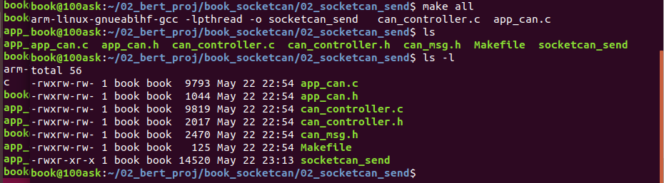
After compiling through the make command, the socket is generated_ Send executable.
(3) Run socket_send
Note: run at 100ask_ Run on the imx6 development board.
nfs files are used here to run.
Give 100ask first_ Power on the imx6ull development board and open the serial port:
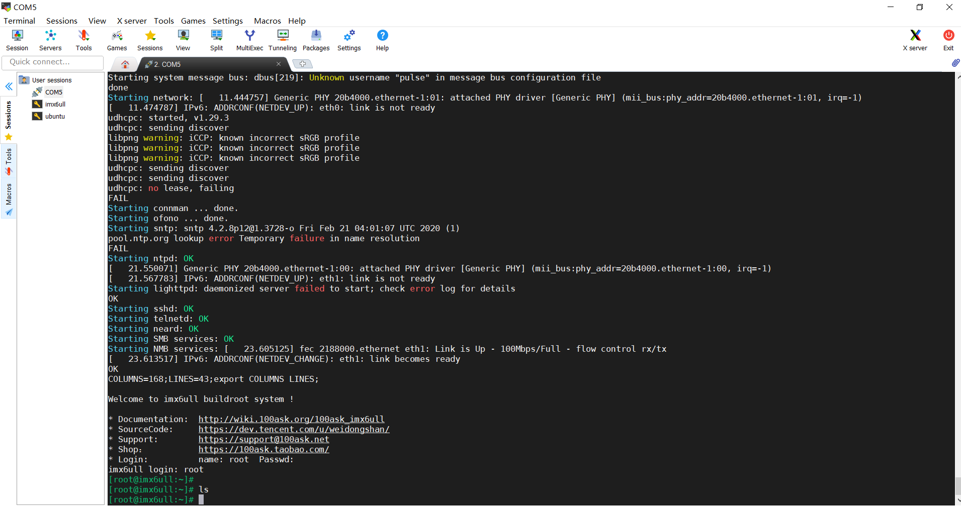
Enter root to log in to the linux system of the development board;
Then mount nfs as follows:
Mount -t nfs -o nolock 192.168.1.100:/home/book /mnt
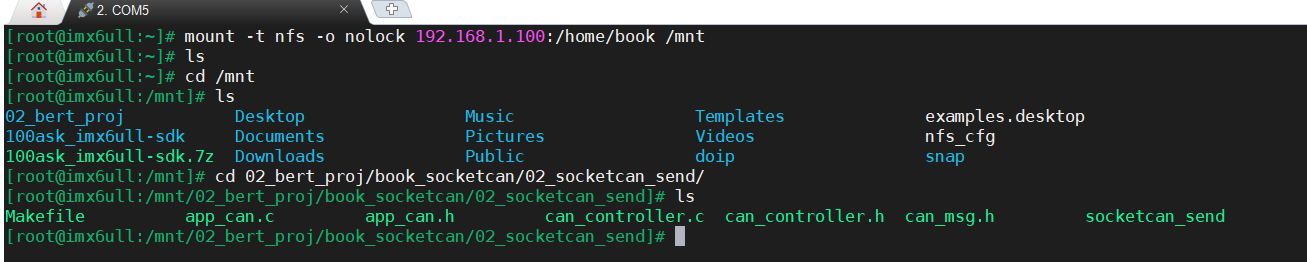
Note: at present, my development board IP: 192.168 1.101, the Ubuntu virtual machine is 192.168 1.100.
Then run/ socketcan_send
If the runtime prompts that permission is not allowed, you can use the chmod command to set the permission:
Chmod 777 socketcan_send
After running, view the print information through the serial port as follows:
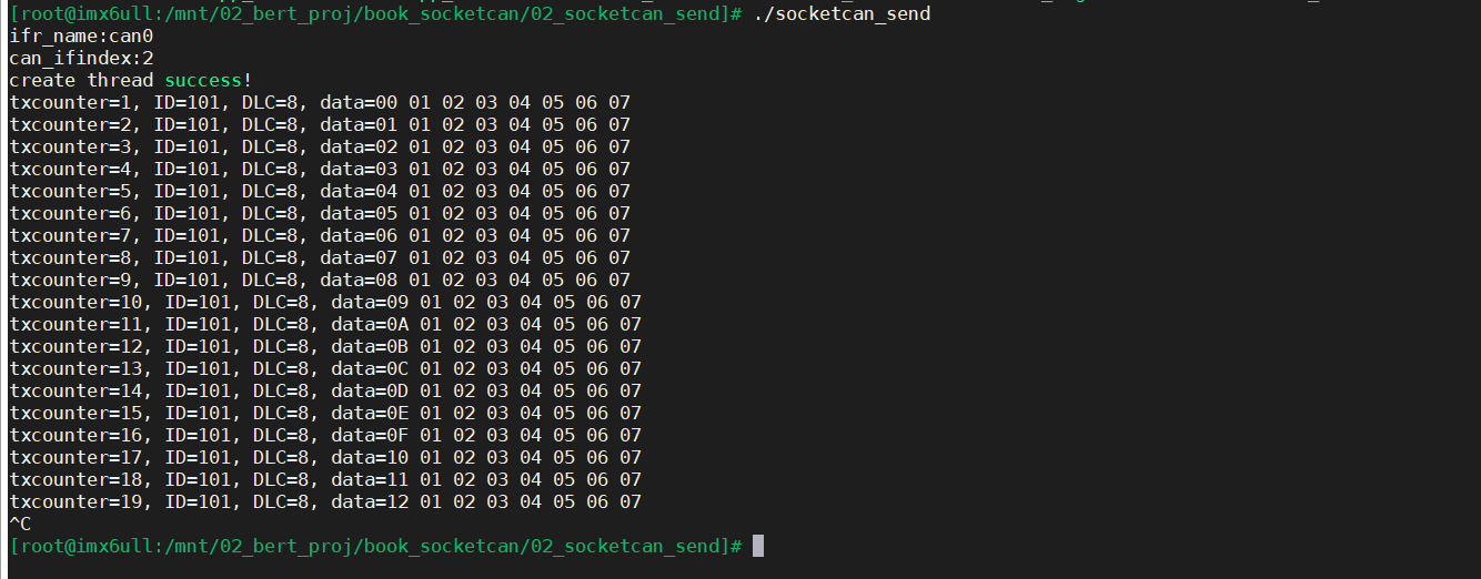
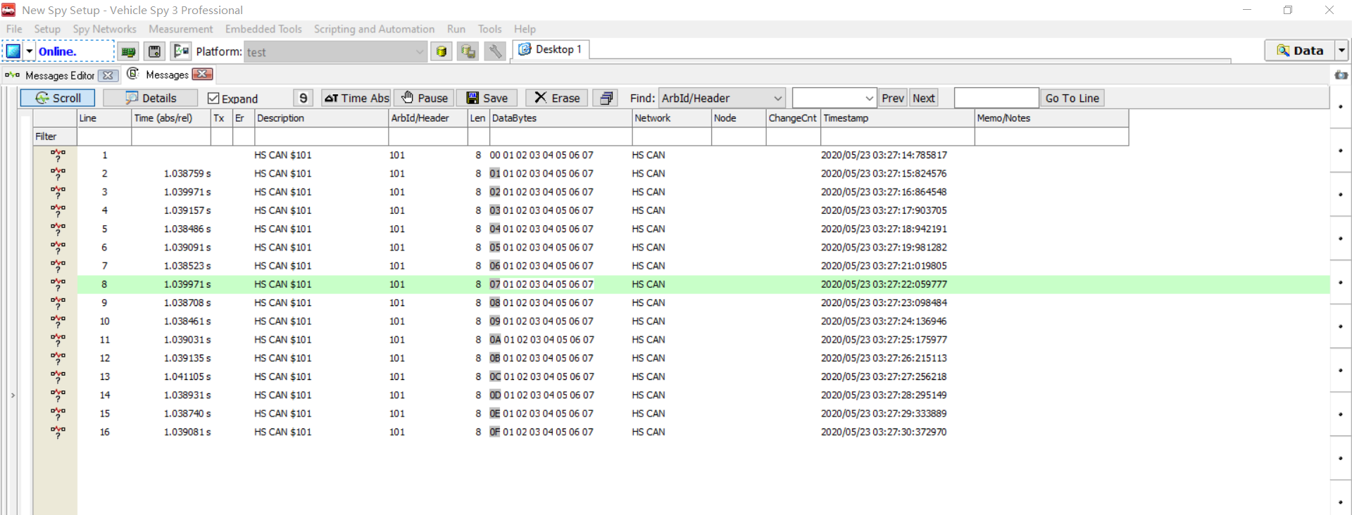
Then observe the test results of the upper computer of vehile spy3 as follows:
The message sends the CAN message with message ID 0x101 periodically according to the time of 1S.
(4) Test summary
So far, we have established the application programming framework under linux through socketcan, and successfully debugged the function programming of sending messages in CAN cycle.
Later, based on this framework, we will understand CAN application programming under linux step by step;
The purpose of the relevant case sections is set as follows:
chapter | objective |
|---|---|
14.4.3 socket_can simple sending example | Simple and direct understanding of sending messages |
14.4.4 socket_can simple receiving example | Simple and direct understanding of received messages |
14.4.5 socket_can receive and send instance | Combined operation of sending and receiving messages |
14.4.4 socket_can simple receiving example
Simple receive instance code directory: "03_socketcan_recv"
We're on 14.4 Chapter 3 has understood the function of sending messages, and has established the framework of application programming under linux; This section focuses on the simple receive function.
Case description:
1. Realize the message receiving message 0x201.
13.4. 4.1 write the implementation function of the abstract framework
(1) Define CAN devices
Refer to the description of "(1) define CAN device" in "14.4.3.1 writing implementation function of abstract framework".
(2) Configure CAN controller
Refer to "(2) configure CAN controller" in "14.4.3.1 writing implementation function of abstract framework".
Because in "14.4.3.1", we only send and set the filter to prohibit all messages. The specific codes are as follows:
109 /*************************************************************/
110 //The filtering rule is disabled. This process does not receive messages and is only responsible for sending them
111 setsockopt(sock_fd, SOL_CAN_RAW, CAN_RAW_FILTER, NULL, 0);
In this case, receiving needs to be configured, and there will be corresponding differences in filter configuration. At present, we are configured to only receive messages with message ID 0x201,
The specific implementation code is as follows:
110 	//Define the receiving rule and only receive messages with the indicator equal to 0x201
111 	struct can_filter rfilter[1];
112 	rfilter[0].can_id = 0x201;
113 	rfilter[0].can_mask = CAN_SFF_MASK;
114 	//Set filtering rules
115 	setsockopt(sock_fd, SOL_CAN_RAW, CAN_RAW_FILTER, &rfilter, sizeof(rfilter));
As an extension, we can also set multiple filters:
Define filters:
struct can_filter rfilter[5];  /*Define 10 filters*/
rfilter[0].can_id = 0x201;
rfilter[0].can_mask = 0x7FF;  /*Filter rule: can_ id & mask = 0x201 & 0x7FF = 0x201*/
rfilter[1].can_id = 0x302;
rfilter[1].can_mask = 0x7FF;  /*Filter rule: can_ id & mask = 0x302& 0x7FF = 0x302*/
rfilter[2].can_id = 0x403;
rfilter[2].can_mask = 0x7FF;  /*Filter rule: can_ id & mask = 0x403& 0x7FF = 0x403*/
rfilter[3].can_id = 0x504;
rfilter[3].can_mask = 0x700;  /*Filter rule: can_ ID & mask = 0x504 & 0x700 = 0x500, that is, the message with message ID 0x5 * * is received*/
rfilter[3].can_id = 0x605;
rfilter[3].can_mask = 0x700;  /*Filter rule: can_ id & mask = 0x504 & 0x700 = 0x600*/
setsockopt(sock_fd, SOL_CAN_RAW, CAN_RAW_FILTER, &rfilter, sizeof(rfilter));
(3) Create CAN receive thread
Refer to the description of "(3) creating CAN receiving thread" in "14.4.3.1 writing implementation function of abstract framework".
(4) CAN message reading function
Refer to "(4) CAN message reading function" in "14.4.3.1 writing implementation function of abstract framework".
(5) CAN message sending function
Refer to "(5) CAN message sending function" in "14.4.3.1 writing implementation function of abstract framework".
(6) CAN abstract structure framework initialization
Refer to "(6) CAN abstract structure frame initialization" description in "14.4.3.1 writing abstract framework implementation function".
14.4. 4.2 writing application layer code
(1) CAN application layer registration instance
Refer to "(1) CAN application layer registration example" in "14.4.3.2 writing application layer code".
(2) CAN application layer initialization
In this simple receiving example, we need to set the callback pointer function in the receiving thread_ RX_ IRQHandler_ Callback is passed in. In this function, the application layer CAN read CAN messages by itself.
105 /**********************************************************************
106 * Function name: void app_can_init(void)
107 * Function Description: CAN application layer initialization
108 * Input parameters: None
109 * Output parameters: None
110 * Return value: None
111 * Modification date version number modified by
112 * -----------------------------------------------
113 * 2020/05/13         V1.0             bert            establish
114 ***********************************************************************/
115 void app_can_init(void)
116 {
117     /**
118     * Application layer for CAN1 structure registration
119     */
120     CAN1_contoller_add();
121
122     /*
123     *Call can_ set_ The controller configures the CAN controller,
124     *Return to can_port, similar to the socket interface in linux socketcan, it is used as a custom CAN channel in the MCU routine
125     */
126     gCAN_COMM_STRUCT.can_port = gCAN_COMM_STRUCT.can_set_controller();
127     /**
128     * Call can_set_interrput configures the CAN receiving interrupt, which is similar to the receiving thread in socketcan
129     */
130     gCAN_COMM_STRUCT.can_set_interrput( gCAN_COMM_STRUCT.can_port, CAN_RX_IRQHandler_Callback );
131 }
(3) Design a simple message receiving function
About void can_ RX_ IRQHandler_ The specific implementation of callback (void) is as follows:
CAN_RX_IRQHandler_Callback is executed circularly in the receiving thread, and the application layer is in can_ RX_ IRQHandler_ The callback function performs gCAN_COMM_STRUCT.can_read read can message.
133 /**********************************************************************
134 * Function name: void CAN_RX_IRQHandler_Callback(void)
135 * Function Description: CAN1 receive interrupt function; In linux, you CAN use threads or timers to read CAN data
136 * Input parameters: None
137 * Output parameters: None
138 * Return value: None
139 * Modification date version number modified by
140 * -----------------------------------------------
141 * 2020/05/13         V1.0             bert            establish
142 ***********************************************************************/
143 void CAN_RX_IRQHandler_Callback(void)
144 {
145     /* Definition of received message */
146     CanRxMsg RxMessage;
147
148     /* Reset received message */
149     memset( &RxMessage, 0, sizeof(CanRxMsg) );
150
151     /* Via can_ The read interface reads the message received by the register */
152     gCAN_COMM_STRUCT.can_read(gCAN_COMM_STRUCT.can_port, &RxMessage);
153
154     /* Copy the read can message to the global message structure g_CAN1_Rx_Message */
155     memcpy(&g_CAN1_Rx_Message, &RxMessage, sizeof( CanRxMsg ) );
156
157 }
In this case, there is no message sending function, and there is no code processing in the main thread, so you only need to run idly.
159 /**********************************************************************
160 * Function name: int main(int argc, char **argv)
161 * Function Description: main function
162 * Input parameters: None
163 * Output parameters: None
164 * Return value: None
165 * Modification date version number modified by
166 * -----------------------------------------------
167 * 2020/05/13         V1.0             bert            establish
168 ***********************************************************************/
169 int main(int argc, char **argv)
170 {
171     /* CAN Application layer initialization */
172     app_can_init();
173
174     while(1)
175     {
176         /* Using the delay function of linux to design the running benchmark of 10ms */
177         usleep(10000);
178     }
179 }
180
13.4. 4.3 case test verification
(1) Write Makfile
The Makefile file contents are as follows:
all:

   arm-linux-gnueabihf-gcc -lpthread -o socketcan_recv  can_controller.c app_can.c

clean:

   rm socketcan_recv
(2) Compile socket_recv
Note: the compilation is in 100ask VMware_ ubuntu18. 04 virtual machine environment.
Enter the socket corresponding to the ubuntu virtual machine_ In the recv directory, execute make all to compile.
The compilation process is as follows:
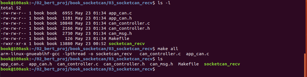
(3) Run socket_recv
Note: run at 100ask_ Run on the imx6 development board.
nfs files are used here to run.
For Nfs mounting, please refer to "14.4,3.3 case test verification".
At 100ask_ Under the imx6 development board environment, execute ". / socket_recv" to run the program;
Then send the data to 100ask through Vhicle Spy3_ The CAN end of imx6 development board sends a message whose message ID is not 0x201, and the message trace is as follows:
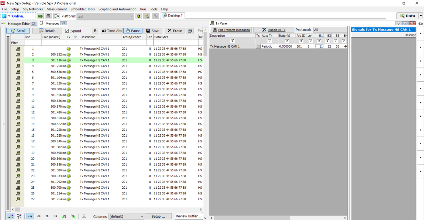
100ask_ The serial port printing information of imx6 development board is as follows:
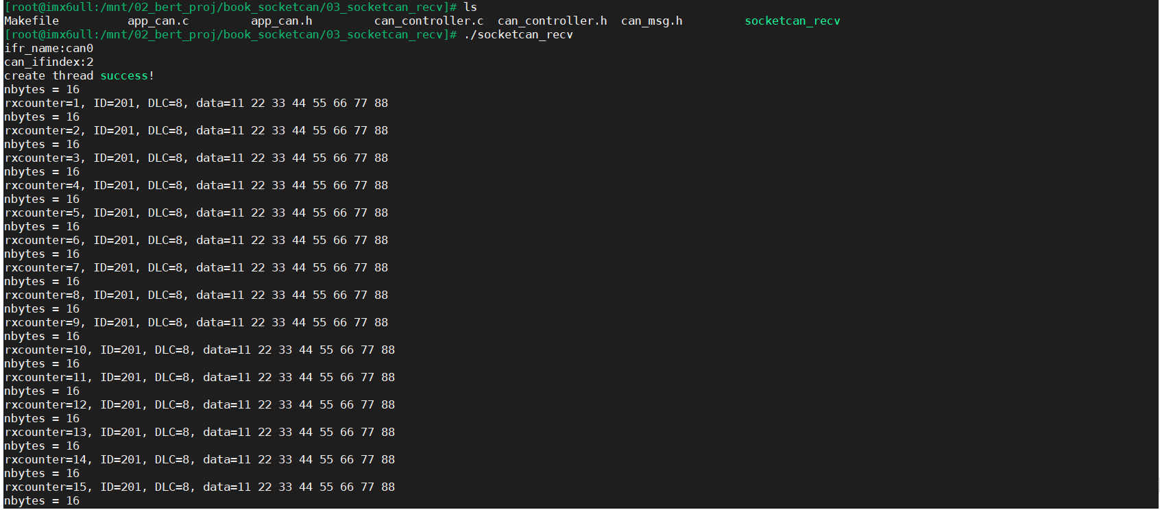
(4) Test summary
So far, we have successfully debugged the functional programming of CAN message reception.
13.4.5 socket_can receive and send instance
Simple receive instance code directory: "04_socketcan_recv_send"
This case integrates "14.4.3 simple sending instance" and "14.4.3 simple receiving instance" to build a combined case with both sending and receiving.
Case description:
- Send the message with message ID: 0x101 within 1 second;
- Receive the message of message 0x201, copy the content to the message of message 0x301 and send it;
13.4. 5.1 write the implementation function of the abstract framework
(1) Define CAN devices
Refer to the description of "(1) define CAN device" in "13.4.3.1 writing implementation function of abstract framework".
Refer to the description of "(1) define CAN device" in "13.4.4.1 writing implementation function of abstract framework".
(2) Configure CAN controller
Refer to "(2) configure CAN controller" in "13.4.3.1 writing implementation function of abstract framework".
Refer to "(2) configure CAN controller" in "13.4.4.1 writing implementation function of abstract framework".
(3) Create CAN receive thread
Refer to the description of "(3) creating CAN receiving thread" in "13.4.3.1 writing implementation function of abstract framework".
Refer to the description of "(3) creating CAN receiving thread" in "13.4.4.1 writing implementation function of abstract framework".
(4) CAN message reading function
Refer to "(4) CAN message reading function" in "13.4.3.1 writing implementation function of abstract framework".
Refer to "(4) CAN message reading function" in "13.4.4.1 writing implementation function of abstract framework".
(5) CAN message sending function
Refer to "(5) CAN message sending function" in "13.4.3.1 writing implementation function of abstract framework".
Refer to "(5) CAN message sending function" in "13.4.4.1 writing implementation function of abstract framework".
(6) CAN abstract structure framework initialization
Refer to "(6) CAN abstract structure frame initialization" description in "13.4.3.1 writing abstract framework implementation function".
Refer to "(6) CAN abstract structure frame initialization" description in "13.4.4.1 writing abstract framework implementation function".
14.4. 5.2 writing application layer code
(1) CAN application layer registration instance
Refer to "(1) CAN application layer registration example" in "13.4.3.2 writing application layer code".
Refer to "(1) CAN application layer registration example" in "13.4.4.2 writing application layer code".
(2) CAN application layer initialization
Refer to "(2) CAN application layer initialization" in "13.4.4.2 writing application layer code".
(3) Design a simple periodic message sending function
Refer to "(3) design a simple message sending function" in "13.4.3.2 writing application layer code".
(4) Design a simple periodic message receiving function
Refer to "(3) design a simple message receiving function" in "13.4.4.2 writing application layer code".
Meanwhile, we need to copy the received message ID:0X201 to the message ID: 0x301 and send it.
On the basis of "13.4.4 simple receiving message", we add a simple logic in the callback function of the receiving thread_ RX_ IRQHandler_ In Callback, call gCAN_. COMM_ STRUCT. can_ read(gCAN_COMM_STRUCT.can_port, &RxMessage); After receiving the message with message ID:0X201, set the flag g_CAN1_Rx_Flag = 1; Then go to the main thread to determine whether this flag is set to 1. If the flag has been received, it is displayed in the void app_ can_ rx_ In test (void), copy the message content with message ID:0X201, and then assign it to the message with message ID:0x301.
Receive thread callback function_ RX_ IRQHandler_ The implementation code of callback is as follows:
231 /**********************************************************************
232 * Function name: void CAN_RX_IRQHandler_Callback(void)
233 * Function Description: CAN1 receive interrupt function; In linux, you CAN use threads or timers to read CAN data
234 * Input parameters: None
235 * Output parameters: None
236 * Return value: None
237 * Modification date version number modified by
238 * -----------------------------------------------
239 * 2020/05/13         V1.0             bert            establish
240 ***********************************************************************/
241 void CAN_RX_IRQHandler_Callback(void)
242 {
243     /* Definition of received message */
244     CanRxMsg RxMessage;
245
246     /* Reset received message */
247     memset( &RxMessage, 0, sizeof(CanRxMsg) );
248
249     /* Via can_ The read interface reads the message received by the register */
250     gCAN_COMM_STRUCT.can_read(gCAN_COMM_STRUCT.can_port, &RxMessage);
251
252     /* Copy the read can message to the global message structure g_CAN1_Rx_Message */
253     memcpy(&g_CAN1_Rx_Message, &RxMessage, sizeof( CanRxMsg ) );
254
255     /* Set the current reception completion flag and judge that the current received message ID is RX_CAN_ID, set g_CAN1_Rx_Flag=1*/
256     if( g_CAN1_Rx_Message.StdId == RX_CAN_ID )
257     {
258         g_CAN1_Rx_Flag = 1;
259     }
260 }
App in main thread_ can_ rx_ The receiving trigger processing function code of test is as follows:
187 /**********************************************************************
188 * Function name: void app_can_rx_test(void)
189 * Function Description: the CAN application layer receives the message processing function, which is used to process the message received in the interrupt function
190 * Input parameters: None
191 * Output parameters: None
192 * Return value: None
193 * Modification date version number modified by
194 * -----------------------------------------------
195 * 2020/05/13         V1.0             bert            establish
196 ***********************************************************************/
197 void app_can_rx_test(void)
198 {
199     unsigned char i=0;
200
201     /* Send message definition */
202     CanTxMsg TxMessage;
203
204     /* A byte is used as a counter in the sent message */
205     static unsigned char rx_counter = 0;
206
207
208     if( g_CAN1_Rx_Flag == 1)
209     {
210         g_CAN1_Rx_Flag = 0;
211
212         /* Send message data filling, and the message cycle is 1 second */
213         TxMessage.StdId = RX_TO_TX_CAN_ID;	  /* The standard identifier is 0x000~0x7FF */
214         TxMessage.ExtId = 0x0000;             /* Extension identifier 0x0000 */
215         TxMessage.IDE   = CAN_ID_STD;         /* Use standard identifier */
216         TxMessage.RTR   = CAN_RTR_DATA;       /* Set as data frame  */
217         TxMessage.DLC   = 8;                  /* Data length: the maximum data length specified in can message is 8 bytes */
218
219         /* Fill data, which can be filled according to the actual application */
220         TxMessage.Data[0] = rx_counter++;      /* Counter used to identify message sending */
221         for(i=1; i<TxMessage.DLC; i++)
222         {
223             TxMessage.Data[i] = g_CAN1_Rx_Message.Data[i];
224         }
225
226         /*  Call can_write send CAN message */
227         gCAN_COMM_STRUCT.can_write(gCAN_COMM_STRUCT.can_port, TxMessage);
228     }
229 }
13.4. 5.3 case test verification
(1) Write Makfile
The Makefile file contains the following contents:
all:

   arm-linux-gnueabihf-gcc -lpthread -o socketcan_recv_send  can_controller.c app_can.c

clean:

   rm socketcan_recv_send
(2) Compile socket_recv_send
Note: the compilation is in 100ask VMware_ ubuntu18. 04 virtual machine environment.
Enter the socket corresponding to the ubuntu virtual machine_ In the send directory, execute make all to compile.
The compilation process is as follows:
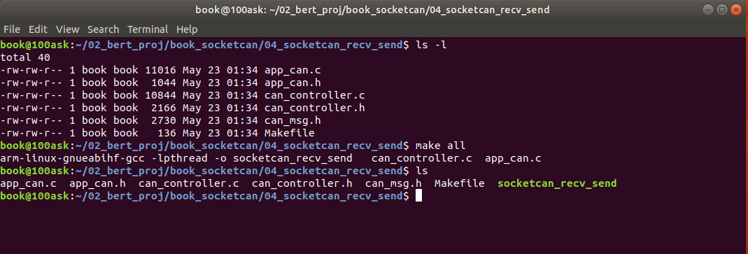
(3) Run socket_recv_send
Note: run at 100ask_ Run on the imx6 development board.
nfs files are used here to run.
For Nfs mounting, please refer to "14.4,3.3 case test verification".
At 100ask_ Under the imx6 development board environment, execute ". / socket_recv_send" to run the program;
Then send the data to 100ask through Vhicle Spy3_ The CAN end of imx6 development board sends a message whose message ID is not 0x201, and the message trace is as follows:
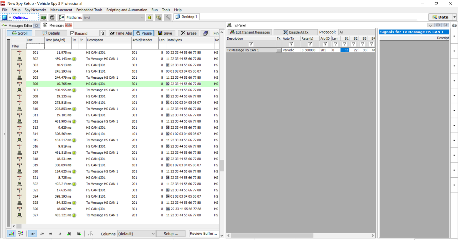
Then observe 100ask_imx6 development serial port printing information is as follows:
(4) Test summary
So far, we have successfully debugged the functional programming of CAN message receiving and sending.
13.5 application of CAN bus in automobile industry
13.5. CAN bus requirements of 1 Depot
The most widely used CAN bus should be in the automotive field. Almost all vehicles support CAN bus. Here is a brief introduction to some automotive related CAN bus requirements.
13.5. 1.1 network topology
The following network topology is roughly consistent with most of the actual vehicle topologies I have developed. It is generally provided by automobile manufacturers to parts suppliers.
As shown in the figure below:
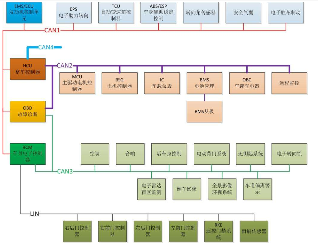
Figure 13.5 1. Vehicle network topology
The general body network is divided into the following 6 local area CAN networks:
Vehicle topology grouping | describe |
|---|---|
PT CAN (PowerTrain CAN) powertrain CAN bus | It is mainly responsible for ECU networking related to vehicle power, which is a CAN network with the highest transmission rate required by the whole vehicle; Generally, it includes the following relevant ECU units: ECM(Engine Control Module), engine control module, SRS (supplementary restraint system), electronic airbag, BMS (battery management system), EPB, electronic park brake and electronic parking system |
CH CAN (Chassis CAN) chassis control CAN bus | CH CAN is responsible for braking / stabilizing / steering of vehicle chassis and four wheels. As it involves vehicle braking / power steering, its network signal priority is also high. Generally, it includes the following relevant ECU units: ABS (antilock brake system), ESP(Electronic Stability Program), EPS (electronic power steering) |
Body CAN body control bus | Body CAN is responsible for the management and control of some intelligent hardware on the body to improve comfort / safety. Its network signal priority is low because the above devices are auxiliary devices. Generally, it includes the following relevant ECU units: AC (air condition) air conditioning AVM(Around View Monitor) 360, BCM(Body Control Module), sunroof, window, fog lamp, steering lamp, wiper... IMMO(Immobilizer) engine anti-theft system TPMS(Tire Pressure Monitoring System) tire pressure monitoring system |
Info can entertainment system bus | Info CAN is an optional auxiliary device, so its priority is also low. It is mainly responsible for the management and control of some intelligent hardware on the body to improve entertainment. Generally, it includes the following relevant ECU units: vaes (video audio entertainment system), vehicle entertainment system (central control), IP(Instrument Pack) combination instrument, and today's digital instrument, which basically has entertainment functions such as music, map, call and so on |
Diagcan diagnostic control bus | DiagCAN bus mainly provides remote diagnosis function. There is only one ECU: Tbox (telematics box) remote control module |
OBD CAN | OBD generally provides an external diagnostic instrument, which is basically connected to the whole vehicle gateway ECU. |
13.5.1.2 CAN message classification
In automobile CAN network, CAN message is mainly divided into three types: application message, network message and diagnosis message.
Both network message and diagnostic message are divided according to different functional requirements, and different protocols for CAN message data are formulated according to different requirements.
(1) CAN application message
CAN application message is mainly used for sending and receiving data information between different ECU nodes in body network, which is related to specific application functions;
Automobile CAN application message shall be defined and released by the vehicle factory, "signal matrix table (excel format)" and "signal matrix (DBC format)".
See "14.5.2 application analysis and examples of can application message" for details.
(2) CAN network management message
The process of configuration management and coordination of all ECU s by automotive electronic system through on-board network is called network management.
Network management CAN control each ECU on the network and issue some command rules to realize the cooperative sleep and wake-up of each ECU. The CAN message used for cooperative control is the network management message.
Network management includes OSEK network management and AUTOSAR network management. Generally, network management is required for front loading plant projects.
(3) CAN diagnostic message
CAN diagnosis mainly realizes vehicle function monitoring, fault detection, recording / storing fault information, storing / reading data, EOL offline detection, ECU upgrade and other functions.
CAN based communication layered model:
OSI layering | Depot diagnostic criteria | OBD standard |
|---|---|---|
Diagnostic application | User defined | ISO15031-5 |
application layer | ISO15765-3 / ISO14229-1 | ISO15031-5 |
Presentation layer | nothing | nothing |
Session layer | ISO15765-3 | ISO15765-4 |
Transport layer | nothing | nothing |
network layer | ISO15765-2 | ISO15765-4 |
data link layer | ISO11898-1 | ISO15765-4 |
physical layer | User defined | ISO15765-4 |
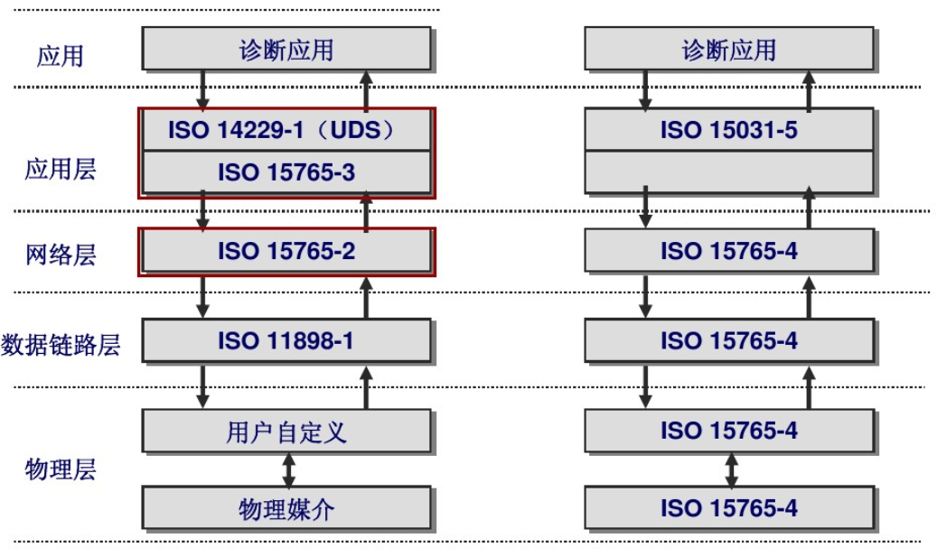
Figure CAN diagnostic service OSI model
13.5. 2 Application Analysis and example of can application message
13.5.2.1 CAN application message definition
After a depot project is started, the depot will provide CAN signal matrix (excel) and DBC signal matrix database according to the needs of the project.
(1) CAN signal matrix excel format
For the file format of signal matrix (excel) provided by the depot, see Chapter 14 code directory: CAN_Signal_Matrix.xlsx,
From can_ Signal_ Matrix. The definition of intercepted message in xlsx is as follows:
ECU_TX_MSG1: (send message periodically, ID: 0x123)
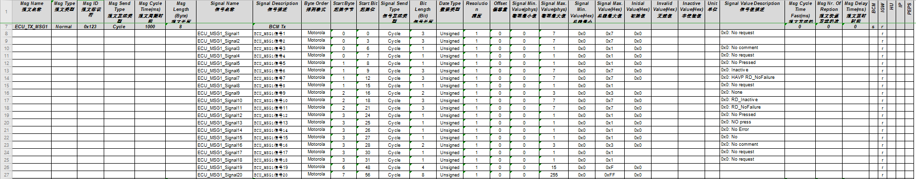
ECU_TX_MSG2: (event sending message, ID: 0x124)
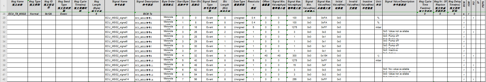
ECU_TX_MSG3: (cycle & event sending message, ID: 0x125)
ECU_RX_MSG1: (event receiving message, ID: 0X201)
It can be seen from the above message definition that the depot will define many attributes of the message, such as message name, message ID, message length, message cycle, message transmission type, signal name, signal start byte, signal length, arrangement format (Intel or Motorola), value range of the signal, signal transmission mode, etc.
(2) CAN signal matrix DBC
The DBC file corresponding to the example CAN matrix "CAN_Signal_Matrix.xlsx" provided in this chapter, which is edited by vector CANdb+ Editor; As shown in the figure below, the message information content displayed in DBC file is consistent with that displayed in excel table. The file format is not the most critical, as long as you understand the requirements of the depot for CAN signal.
Figure DBC of CAN signal matrix
13.5.2.2 CAN application message sending rules
We mentioned that the depot will provide can signal matrix table and define periodic message, event message and periodic event mixed message. Where are the general rules for defining these signals? Generally, the depot will provide the communication specification of CAN bus, and the depot will define the can signal matrix according to the communication specification.
The following is the communication specification XXX Communication Requirement Specification.pdf of a vehicle factory. Its specification directory is shown in the figure below. It CAN be seen from the directory that it mainly introduces the relevant rules of CAN physical layer, data link layer, communication interaction layer and so on.
In this section, we mainly introduce the content related to "4 Interaction Layer" of communication interaction layer related to application message: CAN Message Send Type.
The sending types of CAN messages are introduced one by one as shown in the previous matrix table as follows:
(1) Periodic message
Periodic message is sent periodically and regularly, and the period is T.
As shown in the figure below:
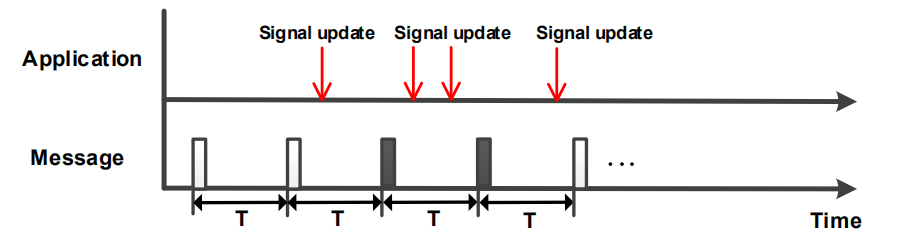
When the system runs, ECU sends CAN message regularly according to cycle T.
(2) Event Message
Send an event type message when an event is triggered, as shown in the following figure:

When the system is running, ECU does not actively send Event type message, but when ECU is triggered by a certain condition (Event), ECU will send three frames of Event message continuously.
Of course, the requirements of the car factory are not only that, but also more other requirements,
For example,
Requirement 1: after triggering the sending of three frame message, the signal is required to be restored to the default value;
Requirement 2: trigger to send three frames, and the interval between frames shall be 50ms;
(3) Periodic and event message
Periodic event hybrid message (CE for short), when there is no event trigger, the message is sent regularly according to cycle T. when there is event trigger, the message is sent according to event trigger mode.
As shown in the figure below:
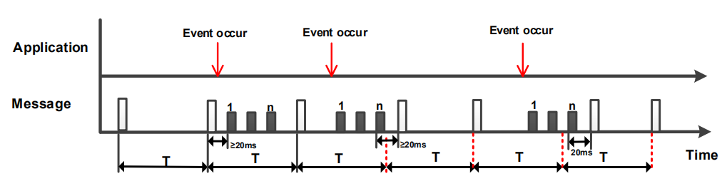
The CAN message sending types defined by the actual depot are not only the above three, but these three are the most important sending methods.
14.5. 2.3 Application examples of automobile CAN application message sending
Through the description in the previous section, we have learned about the three application message sending types in the depot specification. Now we start at 100ask_ Test on imx6 development board to meet the requirements of application message of depot.
We have explained the application programming framework of linux socketcan in detail in "14.4 basic application programming of linux socketcan". Now we will carry out the case application programming of this chapter based on "14.4.5 receiving and sending examples of socketcan", focusing on app_can.c programming, can_controller.c can be completely used.
For the following application programming, we use 14.5 CAN message in CAN message matrix introduced in 2.1.
(1) Preparation of linux can programming framework
Use the code "04_socketcan_recv_send" in the case, and rename the copied folder "06_socketcan_ecu_application".
In app_ can. Message ID defined in C file:
30 /**************Macro definition**************************************************/
31 /* CAN message ID sent in test cycle in this routine */
32 #define TX_CAN_CYCLIC_ID    0X123
33 #define TX_CAN_EVENT_ID     0X124
34 #define TX_CAN_CE_ID        0X125
35
36 /* Test the received CAN message ID in this routine */
37 #define RX_CAN_ID           0x201
(2) Implementation of periodic message
Implementation functions:
A. Program to realize periodic sending message ID:0x123, and cycle T is 1000ms.
The code implementation is as follows:
136 /**********************************************************************
137 * Function name: void app_can_cyclicmsg_test(void)
138 * Function Description: CAN application layer test sends periodic message (ID:0X123)
139 * Input parameters: None
140 * Output parameters: None
141 * Return value: None
142 * Modification date version number modified by
143 * -----------------------------------------------
144 * 2020/05/13         V1.0             bert            establish
145 ***********************************************************************/
146 void app_can_cyclicmsg_test(void)
147 {
148     // Run the CAN test program based on 10ms
149
150     unsigned char i=0;
151
152     /* Send message definition */
153     CanTxMsg TxMessage;
154
155     /* A byte is used as a counter in the sent message */
156     static unsigned char tx_counter = 0;
157
158     /* Taking 10ms as the benchmark, set the period of running code after the processing function to 1 second through the timer counter*/
159     static unsigned int timer =0;
160     if(timer++>100)
161     {
162         timer = 0;
163     }
164     else
165     {
166         return ;
167     }
168
169     /* Send message data filling, and the message cycle is 1 second */
170     TxMessage.StdId = TX_CAN_CYCLIC_ID;	  /* The standard identifier is 0x000~0x7FF */
171     TxMessage.ExtId = 0x0000;             /* Extension identifier 0x0000 */
172     TxMessage.IDE   = CAN_ID_STD;         /* Use standard identifier */
173     TxMessage.RTR   = CAN_RTR_DATA;       /* Set as data frame  */
174     TxMessage.DLC   = 8;                  /* Data length: the maximum data length specified in can message is 8 bytes */
175
176     /* Fill data, which can be filled according to the actual application */
177     TxMessage.Data[0] = tx_counter++;       /* Counter used to identify message sending */
178     for(i=1; i<TxMessage.DLC; i++)
179     {
180         TxMessage.Data[i] = i;
181     }
182
183     /*  Call can_write send CAN message */
184     gCAN_COMM_STRUCT.can_write(gCAN_COMM_STRUCT.can_port, TxMessage);
185
186 }
(3) Implementation of event message
Implementation functions:
A. When the signal ECU_RX_MSG1_signal1=1 of a frame message (ID: 0x201) is received by programming, the event message (ID:0x124) is triggered to send, so that ECU_MSG2_signal2 (Byte1 byte) = 2 and the time interval between two frames of messages is 50ms.
B. Event triggering condition: message (ID:0x201) is received and ECU_RX_MSG1_signal1 (Byte0 byte bit0) is 1
The code implementation is as follows:
188 /**********************************************************************
189 * Function name: void app_can_eventmsg_test(void)
190 * Function Description: CAN application layer test sends event message (ID:0X124)
191 * Input parameters: None
192 * Output parameters: None
193 * Return value: None
194 * Modification date version number modified by
195 * -----------------------------------------------
196 * 2020/05/13         V1.0             bert            establish
197 ***********************************************************************/
198 void app_can_eventmsg_test(void)
199 {
200     unsigned char i=0;
201
202     /* A byte is used as the event trigger counter in the sent message */
203     static unsigned char tx_counter = 0;
204
205     /* Send message definition */
206     CanTxMsg TxMessage;
207
208     if( g_CAN1_Rx_Event_Flag == 1 )
209     {
210 	g_CAN1_Rx_Event_Flag = 0;
211 	printf("Message:0x124 is Triggered!\n");
212
213         /* Send message data filling, and the message cycle is 1 second */
214         TxMessage.StdId = TX_CAN_EVENT_ID;	  /* The standard identifier is 0x000~0x7FF */
215         TxMessage.ExtId = 0x0000;             /* Extension identifier 0x0000 */
216         TxMessage.IDE   = CAN_ID_STD;         /* Use standard identifier */
217         TxMessage.RTR   = CAN_RTR_DATA;       /* Set as data frame  */
218         TxMessage.DLC   = 8;                  /* Data length: the maximum data length specified in can message is 8 bytes */
219
220         /* Fill data, which can be filled according to the actual application */
221         for(i=0; i<TxMessage.DLC; i++)
222         {
223             TxMessage.Data[i] = 0x00;
224         }
225         /* Fill data, which can be filled according to the actual application */
226 	tx_counter = 0;
227
228 	/*Update frame 1 data*/
229 	TxMessage.Data[1] = 0x02;
230 	TxMessage.Data[7] = (++tx_counter);
231         /*  Call can_write send CAN message, frame 1 */
232         gCAN_COMM_STRUCT.can_write(gCAN_COMM_STRUCT.can_port, TxMessage);
233 	/*Delay 50ms as event message interval*/
234 	usleep(50000);
235
236 	/*Update frame 2 data*/
237 	TxMessage.Data[1] = 0x02;
238 	TxMessage.Data[7] = (++tx_counter);
239 	/*  Call can_write send CAN message, frame 2 */
240         gCAN_COMM_STRUCT.can_write(gCAN_COMM_STRUCT.can_port, TxMessage);
241 	/*Delay 50ms as event message interval*/
242 	usleep(50000);
243
244 	/*Update frame 3 data*/
245 	TxMessage.Data[1] = 0x02;
246 	TxMessage.Data[7] = (++tx_counter);
247 	/*  Call can_write send CAN message, frame 3 */
248         gCAN_COMM_STRUCT.can_write(gCAN_COMM_STRUCT.can_port, TxMessage);
249 	/*Delay 50ms as event message interval*/
250 	usleep(50000);
251     }
252 }
(4) Implementation of periodic event message
Implementation functions:
A. Program to realize periodic sending message (ID: 0x125);
B. When the signal ECU_RX_MSG1_signal2=1 of one frame message (ID: 0x201) is received, it triggers the sending of periodic event message (ID:0x125), so that ECU_MSG3_signal9 (Byte1 byte bit0) = 1, and three frames are sent continuously, and the time interval between two frames is 50ms. After three frames are sent, it is restored to ECU_MSG3_signal5=0;
A. Event triggering condition: message (ID:0x201) is received and ECU_RX_MSG1_signal2 (Byte0 byte bit1) is 1
The code implementation is as follows:
255 /**********************************************************************
256 * Function name: void app_can_cycliceventmsg_test(void)
257 * Function Description: CAN application layer test sends periodic event mixed message (ID:0X125)
258 * Input parameters: None
259 * Output parameters: None
260 * Return value: None
261 * Modification date version number modified by
262 * -----------------------------------------------
263 * 2020/05/13         V1.0             bert            establish
264 ***********************************************************************/
265 void app_can_cycliceventmsg_test(void)
266 {
267     unsigned char i=0;
268
269     /* Send message definition */
270     CanTxMsg TxMessage;
271
272     /* A byte is used as the event trigger counter in the sent message */
273     static unsigned char tx_counter = 0;
274
275     /* Taking 10ms as the benchmark, set the period of running code after the processing function to 1 second through the timer counter*/
276     static unsigned int timer =0;
277
278     if( g_CAN1_Rx_CE_Flag == 1)
279     {
280 	g_CAN1_Rx_CE_Flag = 0;
281 	printf("Message:0x125 is Triggered!\n");
282
283 	/* Send message data filling, and the message cycle is 1 second */
284         TxMessage.StdId = TX_CAN_CE_ID;	     /* The standard identifier is 0x000~0x7FF */
285         TxMessage.ExtId = 0x0000;             /* Extension identifier 0x0000 */
286         TxMessage.IDE   = CAN_ID_STD;         /* Use standard identifier */
287         TxMessage.RTR   = CAN_RTR_DATA;       /* Set as data frame  */
288         TxMessage.DLC   = 8;                  /* Data length: the maximum data length specified in can message is 8 bytes */
289
290         /* Clear data area */
291         for(i=0; i<TxMessage.DLC; i++)
292         {
293             TxMessage.Data[i] = 0x00;
294         }
295 	/* Fill data, which can be filled according to the actual application */
296 	tx_counter = 0;
297
298         /*Update frame 1 data*/
299 	TxMessage.Data[1] = 0x01;
300 	TxMessage.Data[7] = (++tx_counter);
301         /*  Call can_write send CAN message, frame 1 */
302         gCAN_COMM_STRUCT.can_write(gCAN_COMM_STRUCT.can_port, TxMessage);
303 	/*Delay 50ms as event message interval*/
304 	usleep(50000);
305
306 	/*Update frame 2 data*/
307 	TxMessage.Data[1] = 0x01;
308 	TxMessage.Data[7] = (++tx_counter);
309 	/*  Call can_write send CAN message, frame 2 */
310         gCAN_COMM_STRUCT.can_write(gCAN_COMM_STRUCT.can_port, TxMessage);
311 	/*Delay 50ms as event message interval*/
312 	usleep(50000);
313
314 	/*Update frame 3 data*/
315 	TxMessage.Data[1] = 0x01;
316 	TxMessage.Data[7] = (++tx_counter);
317 	/*  Call can_write send CAN message, frame 3 */
318         gCAN_COMM_STRUCT.can_write(gCAN_COMM_STRUCT.can_port, TxMessage);
319 	/*Delay 50ms as event message interval*/
320 	usleep(50000);
321     }
322
323     /* Taking 10ms as the benchmark, set the period of running code after the processing function to 1 second through the timer counter*/
324     if(timer++>100)
325     {
326         timer = 0;
327     }
328     else
329     {
330         return ;
331     }
332
333     /* Send message data filling, and the message cycle is 1 second */
334     TxMessage.StdId = TX_CAN_CE_ID;	  /* The standard identifier is 0x000~0x7FF */
335     TxMessage.ExtId = 0x0000;             /* Extension identifier 0x0000 */
336     TxMessage.IDE   = CAN_ID_STD;         /* Use standard identifier */
337     TxMessage.RTR   = CAN_RTR_DATA;       /* Set as data frame  */
338     TxMessage.DLC   = 8;                  /* Data length: the maximum data length specified in can message is 8 bytes */
339
340     /* Fill data, which can be filled according to the actual application */
341     for(i=1; i<TxMessage.DLC; i++)
342     {
343 	TxMessage.Data[i] = 0x00;
344     }
345
346     /*  Call can_write send CAN message */
347     gCAN_COMM_STRUCT.can_write(gCAN_COMM_STRUCT.can_port, TxMessage);
348 }
(4) Case test
Step 1: test cycle message
Run socket_ecu_test, the serial port print information is as follows:
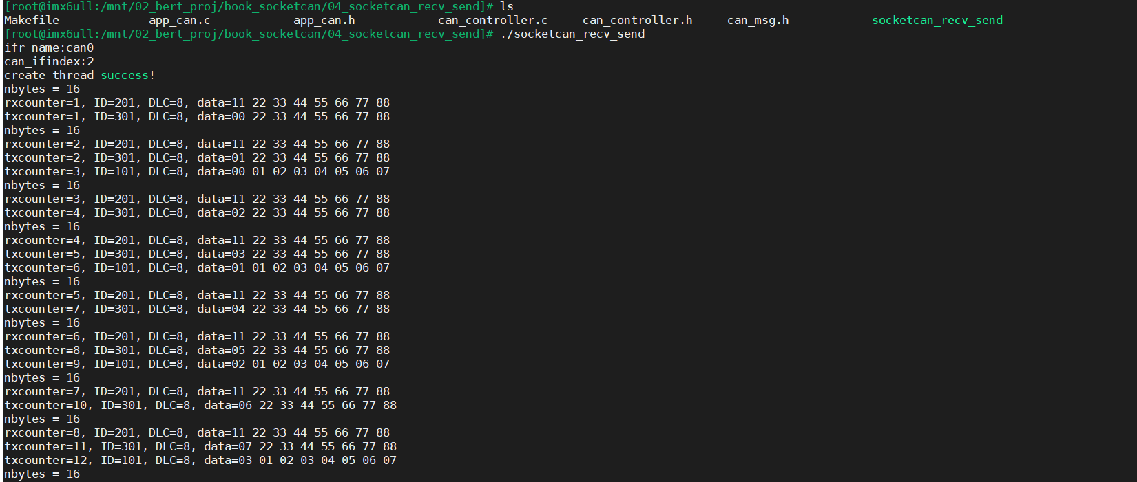
Then observe the message trace obtained by Vehicle Spy3 software, as shown below:
Message ID:0x123,0x125 both messages are sent in 1000ms cycle;
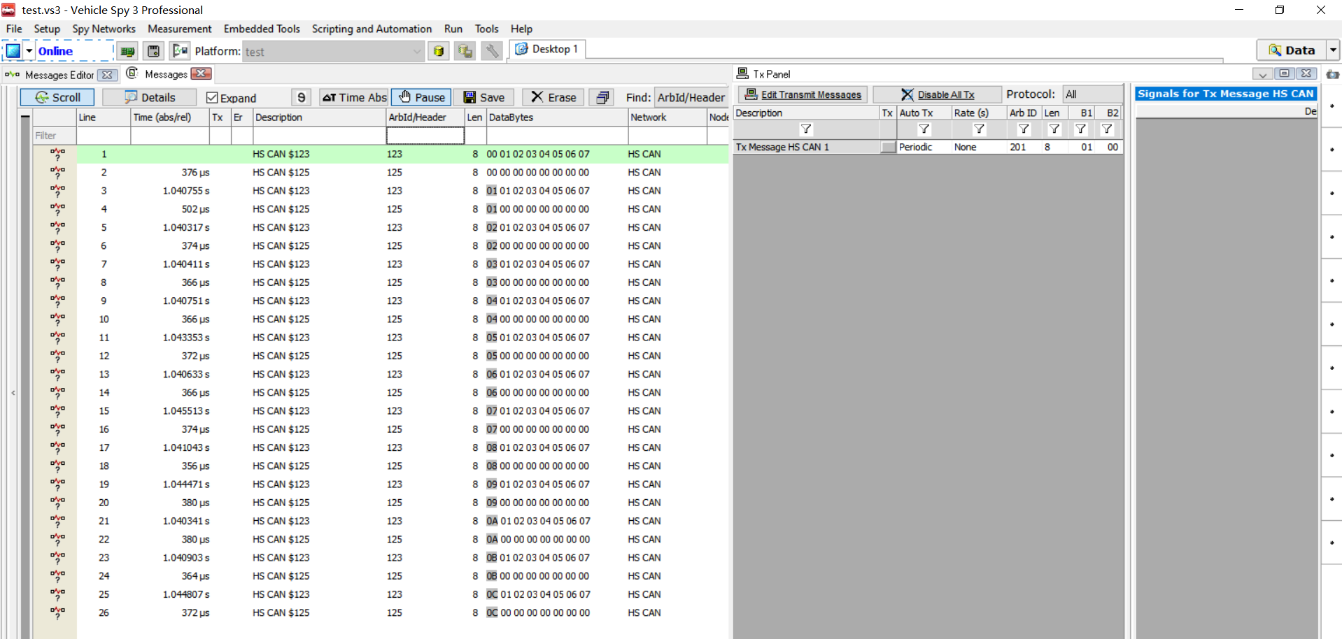
Step 2: test event message
On the Vehicle Spy3 software, the message ID:0X201,0X124 is filtered out in Messages
Then manually click the message with ID:0X201 on the Tx Panel on the right, and the record of Messages on the left is 100ask_imx6 development board sends 3 Messages with frame ID:0x124.
It can be seen from the serial port printing information of the development board: "Message:0x124 is Triggered!", After this print message, there are three frames of messages with ID:0x124.
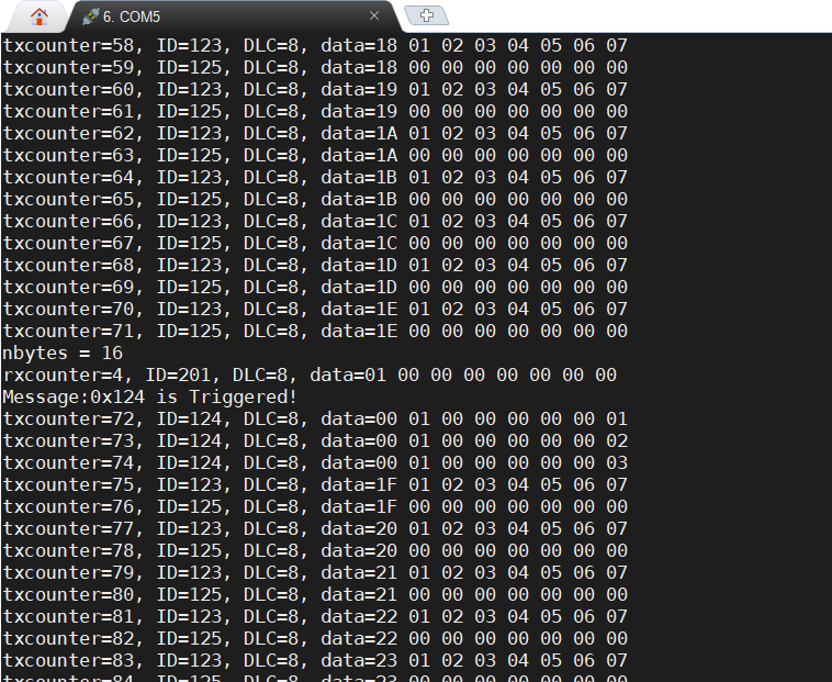
Observe the trace of Messages on the left, as shown in the following figure:
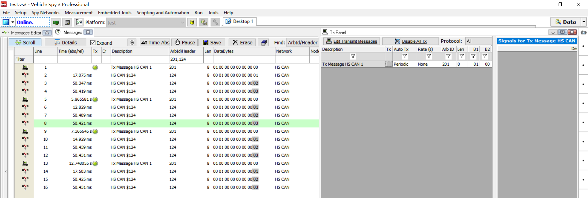
Step 3: Test periodic event message
On the Vehicle Spy3 software, the message ID:0X201,0X125 is filtered out in Messages
Then manually click the message with ID:0X201 on the Tx Panel on the right, and the record of Messages on the left is 100ask_imx6 development board sends three Messages with frame ID:0x125, but the message data is different from the default data. The data content Byte7 is 0x01, 0x02 and 0x03 in turn.
It can be seen from the serial port printing information of the development board: "Message:0x125 is Triggered!", After this print message, there are three frames of messages with ID:0x124.
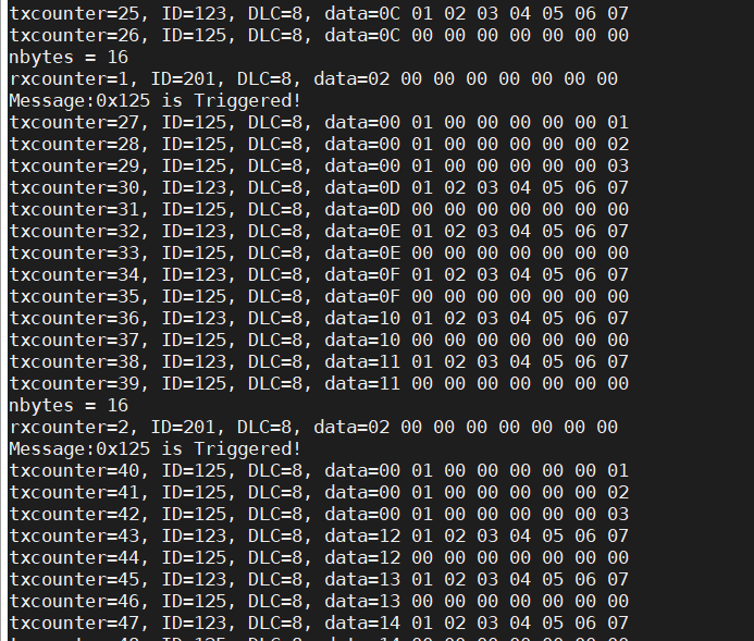
Observe the trace of Messages on the left, as shown in the following figure:
ID:0X125 normally sends the default message in a cycle of 1000ms. When the message of ID:201 triggers an event, it causes ID:0X125 to send an event message.
(5) Improvement of event message sending
Through the previous steps, we have learned about the sending types of application messages and the ways to realize different sending types, but there is a defect in the above event processing, that is, when the event is triggered, the message interval is realized through the ucsleep() function during sending. This delay will make the cycle of periodic messages longer, which CAN be found by observing the CAN message trace.
Here, a small improvement is made to the case "06_socketcan_ecu_application". The trigger event is processed by cycle counting. For details, please see the case code "07_socketcan_ecu_application_new".