Since learning the touch screen driver involves interrupt and I2C related knowledge, let's first introduce the I2C driver framework.
Relationship between touch screen and I2C bus
For the basic concepts and principles of I2C, please refer to my blog: summary of [bare metal] embedded related problems (II. I2C communication concept)
Hardware connection
The connection mode between SoC and touch screen is shown in the figure below. The function of the firmware burned in the touch screen IC, on the one hand, controls the touch screen panel, on the other hand, receives the I2C signal from the main device. For our development, we only need to pay attention to the I2C bus interacting with us, and others don't care.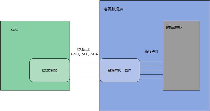
Driver software structure
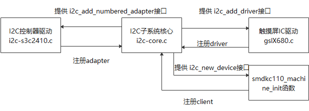
It can be seen that writing I2C related drivers requires two drivers: I2C controller (host) and I2C device (slave). In fact, the driver of the slave needs to be provided passively. However, I2C core already supports the registration of these two drivers.
I2C drive frame
Two I2C driver implementation methods are provided in the kernel (under the drivers/i2c directory):
1) The first method is called I2C dev, which only encapsulates the I2C basic operation of the host (I2C master, generally the I2C controller built in the SoC), and provides the corresponding operation interface (the basic interface for accessing the slave hardware device) to the application layer;
2) The second I2C driver is that all I2C operations are implemented in the driver layer and directly provide the final results to the application layer. The application layer does not even need to know that I2C exists. For example, the capacitive touch screen driver directly provides the application layer with the operation interface of / dev/input/event1. The application layer programmers do not know that I2C is involved in event1. This is the focus of our follow-up analysis.
Four key structures of I2C subsystem:
struct i2c_adapter				I2C Adapter, representing SoC Internal I2C Controller related registers and other information structures
struct i2c_algorithm			I2C Algorithm( I2C A method of timing in which a controller operates a slave i2c_adapter Is a pointer,
								Can point to different algo,This also shows that a host can operate multiple slaves with different algorithms
struct i2c_client				I2C(Slave) device information, similar to that of platform bus platform_device
struct i2c_driver				I2C(Slave) device driver, similar to platform bus platform_driver
It can be seen that the design idea of I2C bus is very similar to that of platform bus. Imagine I2C core In C, I2C is provided respectively_ Client and I2C_ The driver's registration interface, and then each time you register, you go to the other party's linked list to find a match (match function). After the match, you pass the device hardware information into the driver through a probe like function for initialization.
i2c-core.c analysis
static int __init i2c_init(void)
{
	int retval;

	retval = bus_register(&i2c_bus_type);
	if (retval)
		return retval;
#ifdef CONFIG_I2C_COMPAT
	i2c_adapter_compat_class = class_compat_register("i2c-adapter");
	if (!i2c_adapter_compat_class) {
		retval = -ENOMEM;
		goto bus_err;
	}
#endif
	retval = i2c_add_driver(&dummy_driver);
	if (retval)
		goto class_err;
	return 0;

class_err:
#ifdef CONFIG_I2C_COMPAT
	class_compat_unregister(i2c_adapter_compat_class);
bus_err:
#endif
	bus_unregister(&i2c_bus_type);
	return retval;
}
This function is the initialization loading function of I2C core, the most important of which is to call this sentence_ register(&i2c_bus_type);, And I2C_ bus_ Type also contains match function and probe function (this is completely similar to the design of platform bus, indicating that the above conjecture is correct).
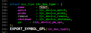
Of course, if you want to know how to match, you can look at the match function. Here is a direct conclusion: when any driver or client registers, the I2C bus will call the match function to register the client Name and driver id_ table. Name for cyclic matching (there can be multiple I d_tables in the driver, one driving device and multiple devices).
And the probe function of driver will be further called in the probe function, driver - > probe().
i2c controller drive
i2c-s3c2410.c source code analysis
This file is the driver file of I2C controller, which is implemented as platform driver.
1. Platform bus mode registration
2. Find the driver and device and confirm their pairing process
3. probe function
1) Fill an i2c_adapter structure (i2c - > adap.algo is the algorithm and function of i2c communication), and call the interface to register it;
2) From platform_device receives hardware information and performs necessary processing (request_mem_region & ioremap, request_irq, etc.);
3) Initialize the hardware (s3c24xx_i2c_init, directly operate the register of I2C controller in 210);
/* s3c24xx_i2c_probe
 *
 * called by the bus driver when a suitable device is found
*/

static int s3c24xx_i2c_probe(struct platform_device *pdev)
{
	struct s3c24xx_i2c *i2c;
	struct s3c2410_platform_i2c *pdata;
	struct resource *res;
	int ret;

	pdata = pdev->dev.platform_data;
	if (!pdata) {
		dev_err(&pdev->dev, "no platform data\n");
		return -EINVAL;
	}

	i2c = kzalloc(sizeof(struct s3c24xx_i2c), GFP_KERNEL);
	if (!i2c) {
		dev_err(&pdev->dev, "no memory for state\n");
		return -ENOMEM;
	}

	strlcpy(i2c->adap.name, "s3c2410-i2c", sizeof(i2c->adap.name));
	i2c->adap.owner   = THIS_MODULE;
	i2c->adap.algo    = &s3c24xx_i2c_algorithm;
	i2c->adap.retries = 2;
	i2c->adap.class   = I2C_CLASS_HWMON | I2C_CLASS_SPD;
	i2c->tx_setup     = 50;

	spin_lock_init(&i2c->lock);
	init_waitqueue_head(&i2c->wait);

	/* find the clock and enable it */

	i2c->dev = &pdev->dev;
	i2c->clk = clk_get(&pdev->dev, "i2c");

	if (IS_ERR(i2c->clk)) {
		dev_err(&pdev->dev, "cannot get clock\n");
		ret = -ENOENT;
		goto err_noclk;
	}

	dev_dbg(&pdev->dev, "clock source %p\n", i2c->clk);

	clk_enable(i2c->clk);

	/* map the registers */

	res = platform_get_resource(pdev, IORESOURCE_MEM, 0);
	if (res == NULL) {
		dev_err(&pdev->dev, "cannot find IO resource\n");
		ret = -ENOENT;
		goto err_clk;
	}

	i2c->ioarea = request_mem_region(res->start, resource_size(res),
					 pdev->name);

	if (i2c->ioarea == NULL) {
		dev_err(&pdev->dev, "cannot request IO\n");
		ret = -ENXIO;
		goto err_clk;
	}

	i2c->regs = ioremap(res->start, resource_size(res));

	if (i2c->regs == NULL) {
		dev_err(&pdev->dev, "cannot map IO\n");
		ret = -ENXIO;
		goto err_ioarea;
	}

	dev_dbg(&pdev->dev, "registers %p (%p, %p)\n",
		i2c->regs, i2c->ioarea, res);

	/* setup info block for the i2c core */

	i2c->adap.algo_data = i2c;
	i2c->adap.dev.parent = &pdev->dev;

	/* initialise the i2c controller */

	ret = s3c24xx_i2c_init(i2c);
	if (ret != 0)
		goto err_iomap;

	/* find the IRQ for this unit (note, this relies on the init call to
	 * ensure no current IRQs pending
	 */

	i2c->irq = ret = platform_get_irq(pdev, 0);
	if (ret <= 0) {
		dev_err(&pdev->dev, "cannot find IRQ\n");
		goto err_iomap;
	}

	ret = request_irq(i2c->irq, s3c24xx_i2c_irq, IRQF_DISABLED,
			  dev_name(&pdev->dev), i2c);

	if (ret != 0) {
		dev_err(&pdev->dev, "cannot claim IRQ %d\n", i2c->irq);
		goto err_iomap;
	}

	ret = s3c24xx_i2c_register_cpufreq(i2c);
	if (ret < 0) {
		dev_err(&pdev->dev, "failed to register cpufreq notifier\n");
		goto err_irq;
	}

	/* Note, previous versions of the driver used i2c_add_adapter()
	 * to add the bus at any number. We now pass the bus number via
	 * the platform data, so if unset it will now default to always
	 * being bus 0.
	 */

	i2c->adap.nr = pdata->bus_num;

	ret = i2c_add_numbered_adapter(&i2c->adap);
	if (ret < 0) {
		dev_err(&pdev->dev, "failed to add bus to i2c core\n");
		goto err_cpufreq;
	}

	platform_set_drvdata(pdev, i2c);

	clk_disable(i2c->clk);

	dev_info(&pdev->dev, "%s: S3C I2C adapter\n", dev_name(&i2c->adap.dev));
	return 0;

 err_cpufreq:
	s3c24xx_i2c_deregister_cpufreq(i2c);

 err_irq:
	free_irq(i2c->irq, i2c);

 err_iomap:
	iounmap(i2c->regs);

 err_ioarea:
	release_resource(i2c->ioarea);
	kfree(i2c->ioarea);

 err_clk:
	clk_disable(i2c->clk);
	clk_put(i2c->clk);

 err_noclk:
	kfree(i2c);
	return ret;
}
Touch screen IC driver
gslX680.c source code analysis
This is a driver written through I2C bus. Need to match i2c_driver and i2c_client. According to the previous analysis, the matching criteria are the name of the client and the ID in the driver_ Name in table does not match.
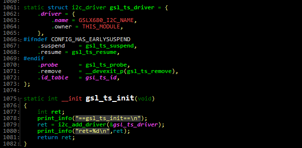
To find i2c_client, I still have to go to mach_xxx.c (especially smdkc110_machine_init function), but now I find i2c_board_info structure.

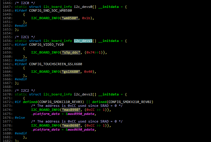
struct i2c_board_info {
	char		type[I2C_NAME_SIZE];			// Device name
	unsigned short	flags;						// attribute
	unsigned short	addr;						// Device slave address
	void		*platform_data;					// Device private data
	struct dev_archdata	*archdata;
#ifdef CONFIG_OF
	struct device_node *of_node;
#endif
	int		irq;								// IRQ number used by the device, corresponding to EINT of CPU
};
You can see i2c_register_board_info finally i2c_board_info joined__ i2c_board_list linked list.
Look up the linked list and find that it returns to I2C core C file, I2C_ scan_ static_ board_ I2c_ is invoked in info. new_ Device, complete I2C_ Registration of client.

Finally, the function call hierarchy:
i2c_add_adapter/i2c_add_numbered_adapter		Register host adapter Time
	i2c_register_adapter
		i2c_scan_static_board_info				At the same time i2c_client Registered
			i2c_new_device
				device_register
gslX680. probe of C
static int __devinit gsl_ts_probe(struct i2c_client *client,
			const struct i2c_device_id *id)
{
	struct gsl_ts *ts;
	int rc;

	print_info("GSLX680 Enter %s\n", __func__);
	if (!i2c_check_functionality(client->adapter, I2C_FUNC_I2C)) {
		dev_err(&client->dev, "I2C functionality not supported\n");
		return -ENODEV;
	}

	ts = kzalloc(sizeof(*ts), GFP_KERNEL);
	if (!ts)
		return -ENOMEM;
	print_info("==kzalloc success=\n");

	ts->client = client;
	i2c_set_clientdata(client, ts);
	ts->device_id = id->driver_data;

	rc = gslX680_ts_init(client, ts);
	if (rc < 0) {
		dev_err(&client->dev, "GSLX680 init failed\n");
		goto error_mutex_destroy;
	}

	gsl_client = client;

	gslX680_init();
	init_chip(ts->client);
	check_mem_data(ts->client);

	rc=  request_irq(client->irq, gsl_ts_irq, IRQF_TRIGGER_RISING, client->name, ts);
	if (rc < 0) {
		print_info( "gsl_probe: request irq failed\n");
		goto error_req_irq_fail;
	}

	/* create debug attribute */
	//rc = device_create_file(&ts->input->dev, &dev_attr_debug_enable);

#ifdef CONFIG_HAS_EARLYSUSPEND
	ts->early_suspend.level = EARLY_SUSPEND_LEVEL_BLANK_SCREEN + 1;
	//ts->early_suspend.level = EARLY_SUSPEND_LEVEL_DISABLE_FB + 1;
	ts->early_suspend.suspend = gsl_ts_early_suspend;
	ts->early_suspend.resume = gsl_ts_late_resume;
	register_early_suspend(&ts->early_suspend);
#endif


#ifdef GSL_MONITOR
	print_info( "gsl_ts_probe () : queue gsl_monitor_workqueue\n");

	INIT_DELAYED_WORK(&gsl_monitor_work, gsl_monitor_worker);
	gsl_monitor_workqueue = create_singlethread_workqueue("gsl_monitor_workqueue");
	queue_delayed_work(gsl_monitor_workqueue, &gsl_monitor_work, 1000);
#endif

	print_info("[GSLX680] End %s\n", __func__);

	return 0;

//exit_set_irq_mode:
error_req_irq_fail:
    free_irq(ts->irq, ts);

error_mutex_destroy:
	input_free_device(ts->input);
	kfree(ts);
	return rc;
}
1. Apply for and fill in the customized touch screen structure ts;
2,gslX680_ts_init registers the input device with the input subsystem;
3,gslX680_init,init_chip,check_mem_data hardware initialization;
4. Initialize the workqueue and apply for IRQ (there is no operation on the upper part, and the lower part is directly activated, and the lower part is mainly used to obtain touch information);
The rest is related to the operation of the touch screen register. Different types of chips are different, so they are not analyzed in detail.