catalogue
- Sample program target
- Write driver
- Writing applications
- Unloading the driver module
In the previous articles, we discussed the basic framework of writing character device driver in Linux system, which is mainly triggered from two aspects: code flow and API function.
In this article, we will write a driver with practical application function based on this:
- In the driver, initialize the GPIO device and automatically create the device node;
- In the application program, open the GPIO device and send the control instruction to set the status of the GPIO port;
Sample program target
Write a driver module: mygpio.ko.
When the driver module is loaded, create a mygpio device in the system, and create four device nodes in the / dev Directory:
/dev/mygpio0 /dev/mygpio1 /dev/mygpio2 /dev/mygpio3
Because we are now simulating GPIO control operation on x86 platform, there is no actual GPIO hardware device.
Therefore, in the driver code, the code related to the hardware uses the macro MYGPIO_HW_ENABLE is controlled, and printk is used to output print information to reflect the operation of the hardware.
In the application, you can open the above four GPIO devices respectively, and set the GPIO status by sending control instructions.
Write driver
The working directory of all the following operations is the same as the previous article, that is, ~ / tmp/linux-4.15/drivers /.
Create driver directories and drivers
$ cd linux-4.15/drivers/
$ mkdir mygpio_driver
$ cd mygpio_driver
$ touch mygpio.c
The contents of mygpio.c file are as follows (there is no need to knock by hand, and there is a code download link at the end of the text):
#include <linux/module.h>
#include <linux/kernel.h>
#include <linux/ctype.h>
#include <linux/device.h>
#include <linux/cdev.h>

// GPIO hardware related macro definitions
#define MYGPIO_HW_ENABLE

// Equipment name
#define MYGPIO_NAME		"mygpio"

// There are 4 GPIO ports in total
#define MYGPIO_NUMBER		4

// Equipment class
static struct class *gpio_class;

// Used to save the device
struct cdev gpio_cdev[MYGPIO_NUMBER];

// Used to save the equipment number
int gpio_major = 0;
int gpio_minor = 0;

#ifdef MYGPIO_HW_ENABLE
// The hardware initialization function is called when the driver is loaded (gpio_driver_init)
static void gpio_hw_init(int gpio)
{
	printk("gpio_hw_init is called: %d. \n", gpio);
}

// Hardware release
static void gpio_hw_release(int gpio)
{
	printk("gpio_hw_release is called: %d. \n", gpio);
}

// Set the status of hardware GPIO, and be investigated when controlling GPIO (gpio_ioctl)
static void gpio_hw_set(unsigned long gpio_no, unsigned int val)
{
	printk("gpio_hw_set is called. gpio_no = %ld, val = %d. \n", gpio_no, val);
}
#endif

// Called when the application opens the device
static int gpio_open(struct inode *inode, struct file *file)
{

	printk("gpio_open is called. \n");
	return 0;
}

// Called when the application controls GPIO
static long gpio_ioctl(struct file* file, unsigned int val, unsigned long gpio_no)
{
	printk("gpio_ioctl is called. \n");

	// Check whether the set status value is legal
	if (0 != val && 1 != val)
	{
		printk("val is NOT valid! \n");
		return 0;
	}

    // Check whether the equipment scope is legal
	if (gpio_no >= MYGPIO_NUMBER)
	{
		printk("dev_no is invalid! \n");
		return 0;
	}

	printk("set GPIO: %ld to %d. \n", gpio_no, val);

#ifdef MYGPIO_HW_ENABLE
    // Operating GPIO hardware
	gpio_hw_set(gpio_no, val);
#endif

	return 0;
}

static const struct file_operations gpio_ops={
	.owner = THIS_MODULE,
	.open  = gpio_open,
	.unlocked_ioctl = gpio_ioctl
};

static int __init gpio_driver_init(void)
{
	int i, devno;
	dev_t num_dev;

	printk("gpio_driver_init is called. \n");

	// Dynamically apply for the equipment number (if it is more rigorous, the return value of the function should be checked)
	alloc_chrdev_region(&num_dev, gpio_minor, MYGPIO_NUMBER, MYGPIO_NAME);

	// Get master device number
	gpio_major = MAJOR(num_dev);
	printk("gpio_major = %d. \n", gpio_major);

	// Create device class
	gpio_class = class_create(THIS_MODULE, MYGPIO_NAME);

	// Create device node
	for (i = 0; i < MYGPIO_NUMBER; ++i)
	{
		// Equipment number
		devno = MKDEV(gpio_major, gpio_minor + i);

		// Initialize cdev structure
		cdev_init(&gpio_cdev[i], &gpio_ops);

		// Register character device
		cdev_add(&gpio_cdev[i], devno, 1);

		// Create device node
		device_create(gpio_class, NULL, devno, NULL, MYGPIO_NAME"%d", i);
	}

#ifdef MYGPIO_HW_ENABLE
    // Initialize GPIO hardware
	for (i = 0; i < MYGPIO_NUMBER; ++i)
	{
		gpio_hw_init(i);
	}
#endif

	return 0;
}

static void __exit gpio_driver_exit(void)
{
	int i;
	printk("gpio_driver_exit is called. \n");

	// Delete devices and device nodes
	for (i = 0; i < MYGPIO_NUMBER; ++i)
	{
		cdev_del(&gpio_cdev[i]);
		device_destroy(gpio_class, MKDEV(gpio_major, gpio_minor + i));
	}

	// Release device class
	class_destroy(gpio_class);

#ifdef MYGPIO_HW_ENABLE
    // Release GPIO hardware
	for (i = 0; i < MYGPIO_NUMBER; ++i)
	{
		gpio_hw_release(i);
	}
#endif

	// Logout equipment number
	unregister_chrdev_region(MKDEV(gpio_major, gpio_minor), MYGPIO_NUMBER);
}

MODULE_LICENSE("GPL");
module_init(gpio_driver_init);
module_exit(gpio_driver_exit);
Compared with the previous articles, the above code is a little more complex, mainly due to the addition of macro definition mygpio_ HW_ The code of the enable control section.
For example, three hardware related functions under the control of this macro definition:
gpio_hw_init() gpio_hw_release() gpio_hw_set()
It refers to the operations related to the initialization, release and status setting of GPIO hardware.
The comments in the code have been relatively perfect. Combined with the function description in the previous articles, it is relatively easy to understand.
As can be seen from the code, the driver uses alloc_chrdev_region function to dynamically register the device number, and automatically create the device node in the / dev directory by using the udev service in the Linux application layer.
Another point: in the above example code, the device operation function only implements the open and ioctl functions, which are determined according to the actual use scenario.
In this example, only how to control the state of GPIO is demonstrated.
You can also add a read function to read the status of a GPIO port.
Controlling GPIO devices and using write or ioctl functions can achieve the goal, but ioctl is more flexible.
Create Makefile file
$ touch Makefile
The contents are as follows:
ifneq ($(KERNELRELEASE),)
	obj-m := mygpio.o
else
	KERNELDIR ?= /lib/modules/$(shell uname -r)/build
	PWD := $(shell pwd)
default:
	$(MAKE) -C $(KERNELDIR) M=$(PWD) modules
clean:
	$(MAKE) -C $(KERNEL_PATH) M=$(PWD) clean
endif
Compile driver module
$ make
Get the driver: mygpio.ko.
Load driver module
Before loading the driver module, first check several places related to the driver equipment in the system.
First look at the / dev directory. There is no device node (/ dev/mygpio[0-3]).
$ ls -l /dev/mygpio*
ls: cannot access '/dev/mygpio*': No such file or directory
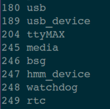
Check the / proc/devices directory again. There is no device number of mygpio device.
$ cat /proc/devices
To facilitate viewing the print information, clean up the dmesg output information:
$ sudo dmesg -c
Now load the driver module and execute the following command:
$ sudo insmod mygpio.ko
When the driver is loaded, use module_init() registered function gpio_driver_init() will be executed, and the print information will be output.
You can also view the print information of the driver module through the dmesg command:
$ dmesg
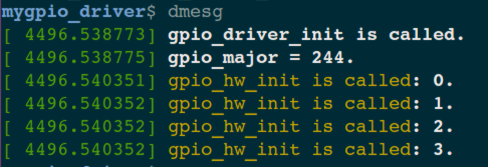
It can be seen that the main device number assigned by the operating system to this device is 244, and the calling information of the initialization function of GPIO hardware is also printed.
At this time, the driver module has been loaded!
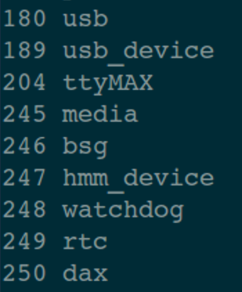
To view the device number displayed in the / proc/devices Directory:
$ cat /proc/devices
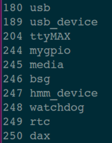
The device has been registered. The main device number is 244.
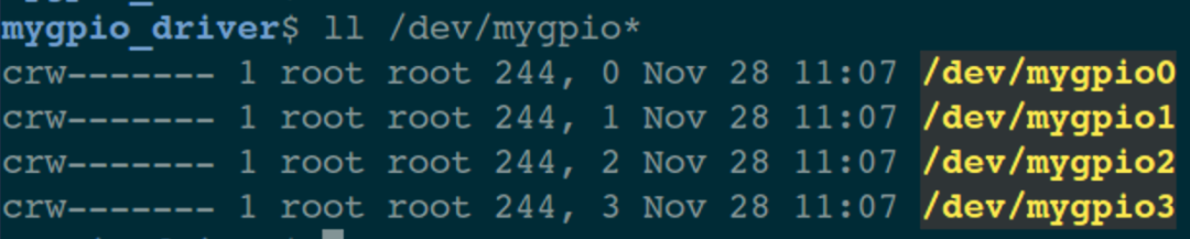
Device node
Because CDEV is used in the initialization function of the driver_ Add and device_ The create functions automatically create device nodes.
Therefore, in the / dev directory, we can see the following four device nodes:
Now that the device driver has been loaded and the device node has been created, the application can control the GPIO hardware device.
application program
The application is still in the ~ / tmp/App / directory.
$ mkdir ~/tmp/App/app_mygpio
$ cd ~/tmp/App/app_mygpio
$ touch app_mygpio.c
The contents of the document are as follows:
#include <stdio.h>
#include <stdlib.h>
#include <unistd.h>
#include <assert.h>
#include <fcntl.h>
#include <sys/ioctl.h>

#define MY_GPIO_NUMBER		4

// 4 device nodes
char gpio_name[MY_GPIO_NUMBER][16] = {
	"/dev/mygpio0",
	"/dev/mygpio1",
	"/dev/mygpio2",
	"/dev/mygpio3"
};


int main(int argc, char *argv[])
{
	int fd, gpio_no, val;

        // Parameter number check
	if (3 != argc)
	{
		printf("Usage: ./app_gpio gpio_no value \n");
		return -1;
	}

	gpio_no = atoi(argv[1]);
	val = atoi(argv[2]);

        // Parameter validity check
	assert(gpio_no < MY_GPIO_NUMBER);
	assert(0 == val || 1 == val);

	// Open GPIO device
	if((fd = open(gpio_name[gpio_no], O_RDWR | O_NDELAY)) < 0){
		printf("%s: open failed! \n", gpio_name[gpio_no]);
		return -1;
	}

	printf("%s: open success! \n", gpio_name[gpio_no]);

	// Control GPIO device status
	ioctl(fd, val, gpio_no);

	// Turn off the device
	close(fd);
}
The above code does not need too much explanation, just pay attention to the order of parameters.
The next step is to compile and test:
$ gcc app_mygpio.c -o app_mygpio
When executing an application, you need to carry two parameters: GPIO device number (0 ~ 3) and the set status value (0 or 1).
Here, set the device / dev/mygpio0 to 1:
$ sudo ./app_mygpio 0 1
[sudo] password for xxx: <Enter user password>
/dev/mygpio0: open success!
How to confirm that the GPIO state of / dev/mygpio0 is indeed set to 1? Of course, look at the print information of the dmesg instruction:
$ dmesg
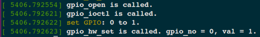
It can be seen from the above printing information that the action of [setting mygpio0 status to 1] has indeed been executed.
Continue to test: set the status of mygpio0 to 0:
$ sudo ./app_mygpio 0 0
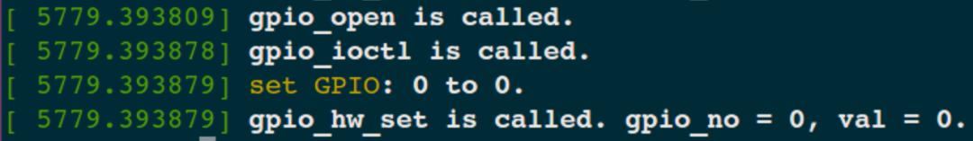
Of course, setting the status of several other GPIO ports can be executed correctly!
Unloading the driver module
Uninstall command:
$ sudo rmmod mygpio
At this time, mygpio of master device No. 244 under / proc/devices no longer exists.
Let's take another look at the print information of dmesg:
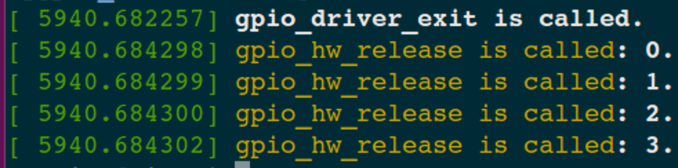
You can see: GPIO in the driver_ driver_ Exit () is called and executed.
In addition, the four device nodes in the / dev directory are also used by the function device_destroy() was deleted automatically!