A design principle of Linux general interrupt subsystem is to hide the underlying hardware implementation as much as possible, so that the driver developers do not pay attention to the underlying implementation. To achieve this goal, the kernel developers must peel off the hardware related content, and then define a series of standard interfaces for the upper layer to access, As long as the upper developers know these interfaces, they can complete the further processing and control of interrupts. The encapsulation of the bottom layer mainly includes two parts:
- Implement interrupt entries of different architectures. This part of the code is usually implemented with asm;
- The interrupt controller is encapsulated and implemented;
The content of this paper is to discuss the implementation details of hardware packaging layer. I will introduce the ARM system. Most of the code is located in the arch/arm / directory of the kernel code tree.
/*****************************************************************************************************/
Statement: the content of this blog is provided by http://blog.csdn.net/droidphone Original, reprint, please indicate the source, thank you!
/*****************************************************************************************************/
1. Interrupt entry of CPU
As we know, the exception and reset vector table of arm has two choices: one is the low-end vector with the vector address at 0x00000000, and the other is the high-end vector with the vector address at 0xffff0000. Linux chooses to use the high-end vector mode, that is, when an exception occurs, the CPU will automatically jump the PC pointer to an address starting from 0xffff0000:
| address | Anomaly type |
|---|---|
| FFFF0000 | reset |
| FFFF0004 | Undefined instruction |
| FFFF0008 | Soft interrupt (swi) |
| FFFF000C | Prefetch abort |
| FFFF0010 | Data abort |
| FFFF0014 | retain |
| FFFF0018 | IRQ |
| FFFF001C | FIQ |
The interrupt vector table is in arch/arm/kernel/entry_armv.S. to facilitate discussion, only some key codes are listed below:
.globl	__stubs_start
__stubs_start:
vector_stub	irq, IRQ_MODE, <span class="hljs-number">4</span>

.<span class="hljs-type">long</span>	__irq_usr			@  <span class="hljs-number">0</span>  (USR_26 / USR_32)
.<span class="hljs-type">long</span>	__irq_invalid			@  <span class="hljs-number">1</span>  (FIQ_26 / FIQ_32)
.<span class="hljs-type">long</span>	__irq_invalid			@  <span class="hljs-number">2</span>  (IRQ_26 / IRQ_32)
.<span class="hljs-type">long</span>	__irq_svc			@  <span class="hljs-number">3</span>  (SVC_26 / SVC_32)

vector_stub	dabt, ABT_MODE, <span class="hljs-number">8</span>

.<span class="hljs-type">long</span>	__dabt_usr			@  <span class="hljs-number">0</span>  (USR_26 / USR_32)
.<span class="hljs-type">long</span>	__dabt_invalid			@  <span class="hljs-number">1</span>  (FIQ_26 / FIQ_32)
.<span class="hljs-type">long</span>	__dabt_invalid			@  <span class="hljs-number">2</span>  (IRQ_26 / IRQ_32)
.<span class="hljs-type">long</span>	__dabt_svc			@  <span class="hljs-number">3</span>  (SVC_26 / SVC_32)

vector_fiq:
disable_fiq
subs pc, lr, #4
...
.globl __stubs_end
__stubs_end:

.equ	stubs_offset, __vectors_start + <span class="hljs-number">0</span>x200 - __stubs_start
.globl	__vectors_start
__vectors_start:
ARM( swi SYS_ERROR0 )
THUMB( svc #0 )
THUMB( nop )
W(b) vector_und + stubs_offset
W(ldr) pc, .LCvswi + stubs_offset
W(b) vector_pabt + stubs_offset
W(b) vector_dabt + stubs_offset
W(b) vector_addrexcptn + stubs_offset
W(b) vector_irq + stubs_offset
W(b) vector_fiq + stubs_offset

.globl	__vectors_end
__vectors_end:
The code is divided into two parts:
- The first part is the real vector jump table, located in__ vectors_start and__ vectors_ Between end;
- The second part is the part dealing with jump, which is located in__ stubs_start and__ stubs_ Between end;
vector_stub irq, IRQ_MODE, 4
After the macro is expanded in the above sentence, the vector is actually defined_ IRQ, according to the cpu mode before entering the interrupt, jump to__ irq_usr or__ irq_svc.
After the macro is expanded in the above sentence, the vector is actually defined_ DABT, according to the cpu mode before entering the interrupt, respectively jump to__ dabt_usr or__ dabt_svc.vector_stub dabt, ABT_MODE, 8
The above two memcpy will__ vectors_ Copy the code from start to 0xffff0000__ stubs_ The code started by start is copied to 0xFFFF0000+0x200, so that when an abnormal interrupt arrives, the CPU can correctly jump to the corresponding interrupt vector entry and execute them.
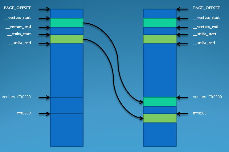
Figure 1.1 interrupt vector copy process of ARM system in Linux
For external devices of the system, IRQ interrupts are usually used, so we only focus on__ irq_usr and__ irq_ The difference between SVC and kernel stack is whether to switch between user stack and kernel stack when entering and exiting interrupt, as well as process scheduling and preemption processing. These details are not discussed here. Both functions eventually enter irq_handler macro:
If multi is selected_ IRQ_ Handler configuration item, which means that the platform code can dynamically set the IRQ handler, and the platform code can modify the global variable: handle_arch_irq, so you can modify the handler of IRQ. Here we discuss the default implementation: arch_irq_handler_default, which is located in arch / arm / include / ASM / entry_ macro_ multi. In S:.macro irq_handler #ifdef CONFIG_MULTI_IRQ_HANDLER ldr r1, =handle_arch_irq mov r0, sp adr lr, BSYM(9997f) ldr pc, [r1] #else arch_irq_handler_default #endif 9997: .endm
	.macro	arch_irq_handler_default
	get_irqnr_preamble r6, lr
1:	get_irqnr_and_base r0, r2, r6, lr
	movne	r1, sp
	@
	@ routine called with r0 = irq number, r1 = struct pt_regs *
	@
	adrne	lr, BSYM(1b)
	bne	asm_do_IRQ
    ......
get_irqnr_preamble and get_ irqnr_ and_ The two base macros are defined by machine level code to obtain the IRQ number from the interrupt controller, and then call asm_do_IRQ, starting from this function, the interrupt program enters the C code. The parameters passed in are IRQ number and register structure pointer. This function is in arch / arm / kernel / IRQ C:
Here, the interrupt program completes the transfer from asm code to C code, and obtains the IRQ number causing the interrupt.
2. Initialization
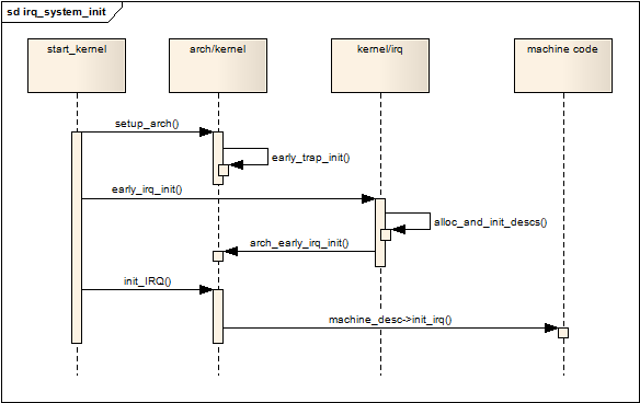
- First, in setup_ In the arch function, early_trap_init is called, which completes the copy and relocation of the interrupt vector described in Section 1.
- Then, start_kernel issues early_irq_init call, early_irq_init belongs to the general logic layer independent of hardware and platform. It completes IRQ_ The memory application of the desc structure fills the default values for some of these fields. After completion, the system related arch_ is called. early_ irq_ The init function completes further initialization, but the ARM system does not implement arch_early_irq_init.
- Next, start_kernel sends init_ IRQ call, which will directly call the board machine_ Init in desc structure_ IRQ callback. machine_desc usually uses machine in the specific code of the board_ Start and machine_ The end macro is defined.
- machine_ desc->init_ irq () completes the initialization of the interrupt controller for each irq_desc structure is equipped with appropriate flow control handler for each irq_desc structure installation irq_chip pointer to point to the irq corresponding to the correct interrupt controller_ At the same time, if the interrupt lines in the platform are multiplexed (multiple interrupts share an irq interrupt line), irq should also be initialized_ Desc to realize the cascade of interrupt controllers.
3. Software abstraction of interrupt controller: struct irq_chip
As in the previous article One of Linux interrupt subsystems: basic principle of interrupt system As described above, all hardware interrupts must be collected by the interrupt controller before reaching the CPU, and the CPU will be notified to process the qualified interrupt request. The interrupt controller mainly completes the following functions:
- Control the priority of each irq;
- After sending an interrupt request to the CPU, provide a mechanism for the CPU to obtain the actual interrupt source (irq number);
- Controlling the electrical trigger conditions of each irq, such as edge trigger or level trigger;
- enable or mask an irq;
- Provide the ability to nest interrupt requests;
- Providing a mechanism for clearing interrupt requests (ack);
- Some controllers also require the CPU to issue eoi instructions (end of interrupt) to the controller after irq processing;
- In smp system, the affinity between irq and cpu is controlled;
The general interrupt subsystem abstracts the interrupt controller into a data structure: struct irq_chip, which defines a series of operation functions, most of which correspond to a function listed above:
The fields are explained as follows:
Name = the name of the interrupt controller, which will appear in / proc/interrupts.
irq_startup is used when starting an IRQ for the first time.
irq_shutdown and IRQ_ Corresponding to starup.
irq_enable enables the IRQ, which is usually called directly_ unmask().
irq_disable disables the IRQ, which is usually called directly_ Mask, in a strict sense, they actually represent different meanings. disable means that the interrupt controller does not respond to IRQ at all. During mask, the interrupt controller may respond to IRQ without notifying the CPU. At this time, the IRQ is in pending state. Similar differences apply to enable and unmask.
irq_ack is used for the CPU's response to the IRQ. It usually indicates that the CPU wants to clear the pending state of the IRQ and is ready to accept the next IRQ request.
irq_mask # mask the IRQ.
irq_unmask # unmask the IRQ.
irq_mask_ack equals irq_mask + irq_ack.
irq_eoi# some interrupt controllers need to send eoi signals after the cpu processes the IRQ. This callback is used for this purpose.
irq_set_affinity is used to set the affinity between the IRQ and the cpu, that is, to notify the interrupt controller. When the IRQ occurs, those CPUs have the right to respond to the IRQ. Of course, with the cooperation of software, the interrupt controller will finally let only one cpu process the request.
irq_set_type , set the electrical trigger condition of IRQ, such as IRQ_TYPE_LEVEL_HIGH or IRQ_TYPE_EDGE_RISING.
irq_set_wake notifies the power management subsystem whether the IRQ can be used as a wake-up source for the system.
The parameters of most of the above function interfaces are irq_data structure pointer, IRQ_ The origin of data structure has been mentioned in the previous article. Only its definition is posted here. Please refer to the notes for the meaning of each field:
According to the type of interrupt controller used by the device, the underlying development of the architecture only needs to implement each callback function in the above interface, and then fill them into IRQ_ In the example of chip structure, the IRQ_ The chip instance is registered with irq_desc.irq_data.chip field, so that each IRQ is associated with the interrupt controller. As long as you know the IRQ number, you can get the corresponding irq_desc structure, and then the interrupt controller can be accessed through the chip pointer.
4. Enter the flow control processing layer
The first function to enter the C code is asm_do_IRQ, in the ARM system, this function simply calls handle_IRQ:
handle_IRQ itself is not very complex:
irq_enter is mainly used to update some system statistics, and at the same time__ irq_ Process preemption is prohibited in the enter macro:
Once the CPU responds to the IRQ interrupt, the ARM will automatically put the I position bit in the CPSR, indicating that new IRQ requests are prohibited until the interrupt control is transferred to the corresponding flow control layer_ irq_ Enable() opens. You may wonder why preemption is prohibited since IRQ interrupts are prohibited at this time? This is because the problem of interrupt nesting should be considered. Once the flow control layer or driver actively passes through local_irq_enable opens IRQ, but the interrupt has not been processed yet. When a new IRQ request arrives, the code will enter IRQ again_ Enter, when the nested interrupt returns this time, the kernel does not want to preempt scheduling, but does not make scheduling action until the outermost interrupt processing is completed. Therefore, preemption is prohibited.
Next, generic_handle_irq called, generic_handle_irq is an API provided by the general logic layer. Through this API, the control of interrupts is passed to and Architecture Irrelevant interrupt flow control layer:
Finally, it will enter the irq registered flow control callback:
5. Cascade of interrupt controller
- The cascade} sub controller at the machine level is located inside the SOC or outside the SOC, but it is a standard configuration of a board series, as shown on the left of Figure 5.1;
- The cascade} sub controller at the device level is located in an external device to collect multiple interrupts sent by the device, as shown on the right side of Figure 5.1;
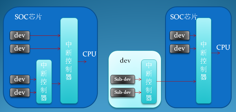
Figure 5.1 cascading type of interrupt controller
For machine level cascading, the cascading initialization code is naturally located in the initialization code of the board (arch / xxx / Mach XXX), because as long as the device using the board or SOC must use the sub controller. For cascading at the device level, because the device is not necessarily the standard device of the system, the cascading operation of the interrupt controller should be implemented in the driver of the device. Because the hardware connection information of the sub controller is known in advance, the kernel can easily reserve the corresponding irq for the sub controller_ Desc structure and irq number are relatively simple to handle. Device level cascading is different. The driver must dynamically determine the irq number and irq of each sub device in the combined device_ Desc structure. In this chapter, I only discuss machine level cascading. Device level association can use the same principle or be implemented as shared interrupt. I will discuss it in the next articles in this series.
To realize the cascade of interrupt controllers, the following key data structure fields and API s of general interrupt logic layer should be used:
irq_desc.handle_irq = IRQ flow control processing callback function. After the sub controller collects multiple IRQs, the output end is connected to one of the IRQ interrupt line input pins of the root controller, which means that when the interrupt of each sub controller occurs, the CPU will only get the IRQ number of the root controller at first, and then enter the IRQ corresponding to the IRQ number_ desc.handle_ IRQ callback, we can not use several flow control functions defined by the flow control layer in the callback. Instead, we need to implement a function by ourselves, which is responsible for obtaining the interrupt source of IRQ from the sub controller and calculating the corresponding new IRQ number, then calling the irq_ corresponding to the new IRQ. desc.handle_ IRQ callback, which uses the standard implementation of the flow control layer.
irq_set_chained_handler() this API is used to set the IRQ corresponding to the IRQ connected between the root controller and the sub controller_ desc.handle_ IRQ callback function, and set IRQ_NOPROBE and IRQ_NOTHREAD and IRQ_NOREQUEST flags, which ensure that the driver will not mistakenly apply for the IRQ, because the IRQ has been used as a cascading IRQ.
irq_set_chip_and_handler() this API also sets IRQ_ Handle in desc_ IRQ callback and irq_chip pointer.
The following example code is located at: / arch / arm / plat-s5p / IRQ EINT c:
int __init s5p_init_irq_eint(void)
{
	int irq;

	for (irq = IRQ_EINT(0); irq <= IRQ_EINT(15); irq++)
		irq_set_chip(irq, &s5p_irq_vic_eint);

	for (irq = IRQ_EINT(16); irq <= IRQ_EINT(31); irq++) {
		irq_set_chip_and_handler(irq, &s5p_irq_eint, handle_level_irq);
		set_irq_flags(irq, IRQF_VALID);
	}

	irq_set_chained_handler(IRQ_EINT16_31, s5p_irq_demux_eint16_31);
	return 0;
}
External interrupt of SOC chip: IRQ_EINT(0) to IRQ_EINT(15), each pin corresponds to an IRQ interrupt line of the root controller. They are normal IRQ without cascading. IRQ_EINT(16) to IRQ_ After the EINT (31) is collected by the sub controller, it is uniformly connected to the root controller, and the number is IRQ_EINT16_31 this interrupt line. You can see the IRQ corresponding to the sub controller_ Chip is s5p_irq_eint, the IRQ of the sub controller is set as the flow control processing function handle of level interrupt by default_ level_ IRQ, they pass the API: irq_set_chained_handler. IRQ if the root controller has 128 interrupt lines_ EINT0--IRQ_ Eint15 usually occupies a continuous range within 128, depending on the actual physical connection. IRQ_EINT16_31 also belongs to the following controller, so its value will also be within 128, but IRQ_EINT16--IRQ_EINT31 is usually in a range other than 128. In this case, the constant NR representing the IRQ quantity_ IRQs must consider this situation and define a sufficient value exceeding 128. The implementation of cascading mainly depends on IRQ_EINT16_31 flow control processing program: s5p_irq_demux_eint16_31. Its final implementation is similar to the following code:
static inline void s5p_irq_demux_eint(unsigned int start)
{
	u32 status = __raw_readl(S5P_EINT_PEND(EINT_REG_NR(start)));
	u32 mask = __raw_readl(S5P_EINT_MASK(EINT_REG_NR(start)));
	unsigned int irq;

	status &= ~mask;
	status &= 0xff;

	while (status) {
		irq = fls(status) - 1;
		generic_handle_irq(irq + start);
		status &= ~(1 << irq);
	}
}
After obtaining the new irq number, its most critical sentence is to call the API of the general interrupt logic layer: generic_handle_irq, then it really transfers the interrupt control right to the interrupt flow control layer.