Linux Routing and Policy Routing
OSI seven-tier reference model


Routing Introduce
Layer 2 switch, Layer 3 route:
The exchange is located in the second layer of the OSI seven-layer model, where the data frame is encapsulated in an Ethernet header that records the mac address of the target network.
Routing is located in the third layer of the OSI seven-layer model, where the packet is encapsulated with an IP header that records the source and destination IP addresses.
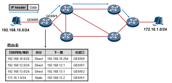
Question 1: If 192.168. The 10.1/24 PC0 must be 192.168 on the same segment. How do 10.2/24 PCs communicate?
In the same network segment, the MAC address of the destination address host is obtained by ARP broadcasting, which encapsulates the data into a data frame and communicates over a physical line.
Question 2: Assume 192.168. PC0 of 10.1/24 should follow 172.16. 1.1/24 PC1 communication, how to achieve?
The destination address of the packets sent by PC0 is cross-network segment. Routers are required to forward packets. Each router maintains a routing table. Many entries are recorded in the routing table, each of which is called a route, and each route contains the corresponding destination network, outbound interface, and next hop (gateway).
When our router When an IP packet is received, it is searched in the routing table according to the destination IP address in the packet. If a best matching table item is found, it is forwarded according to the interface in the table item and the next hop. If no matching table item is found, the packet is discarded and the router sends the packet to the source of the packet. Send an ICMP error message informing that the packet is not reachable.
Router
What the router does: The router supports various routing protocols (RIP, OSPF), fills the routing table according to the routing protocol, and forwards packets according to the entries of the routing table.
-
Router knows destination address
-
Discover possible routes to the destination address
-
Choose the best path (routing table)
-
Maintain routing information
-
Forward IP data
Routing table
IP Network Routing Table
The IP routing table is the key to the router's ability to work, which is equivalent to a map for packet forwarding. In computer networks, routing tables are also called routing information databases (RIP).
Huawei Communications products with routing capabilities (e.g. routers, three-tier switches, etc.) use the display ip routing-table command to view routing tables
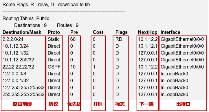
| Key Items | Explain | Give an example |
|---|---|---|
| Target Network/Mask | Target network plus mask length, difference 2.2. 2.0/24 and 2.2. 2.0/30 | 192.168.1.0/24 |
| Agreement | Indicates the protocol through which the route was acquired | direct, static, dynamic routing protocol (OSPF, RIP) |
| priority | Based on protocol judgment, when multiple reachable routes with different protocols are found, the lower the priority, the better | For example, Huawei router: Direct-0; OSPF-10; Static-69; IGRP-80; RIP-110; OSPFASE-150; BGP-170 |
| Expenses | Routing cost, cost value or metric value are parameters used by the same routing protocol to select the best route. The smaller the general value, the better | |
| sign | Routing table identification | U: This route is currently available |
| G: The route is to a gateway (router) | ||
| H: The route is to one host | ||
| D: The route has been downloaded to the underlying forwarding information table | ||
| M: The route has been modified by the redirection message | ||
| R: Routes reinitialized using dynamic routes | ||
| Next Jump | Next hop IP address of message | 192.168.10.254 |
| Out Interface | A forwarding interface to a destination, also known as an outgoing interface or forwarding interface | GE0/0/0 |
Source of Routing Entries
connected route
Direct Connection Routing - Routing of the segment where the direct connection port is located
-
When initialized, the router knows only the segment where its direct connection port is located. Routers automatically write routes from the network segment where the interface is located to the routing table, which are called direct routes, and their Protocol s in the routing table are Direct.
-
The precondition for direct connection routing to appear in the routing table is that both the physical state and protocol state of the interface are UP.
An example of direct-connect routing is when an IP address 192.168 is configured on an interface of a router. When 1.1/24 (the network number of the address is 192.168.1.0/24) and the physical/protocol state of the interface is up, the network number of the direct connection is automatically written to the routing table to form a direct connection routing table entry.
Static Routing
Static Routing - Routing entries manually configured by the network administrator
- ip route-static network number mask next hop IP address
- ip route-static network number mask out interface
- ip route-static network number mask out interface next hop IP address
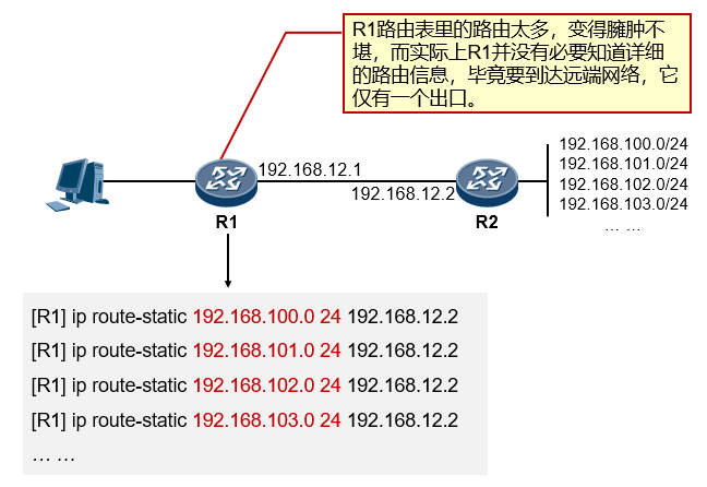
Example of static routing: R1 can create two separate routes to 192.168. 100.0/24 and 192.168. Routing of 20.0/24 segments. Static routing is convenient and controllable, but if there are many target networks, it is necessary to configure multiple static routes. Large-scale networks with many facets are unable to cope with dynamic topology changes, such as 192.168. 100.0/24 This network is down, R1 will still forward packets to R2 without being aware, R2 will discard the packets.

Examples of default routes: R1 to 192.168. 100.0/24, 192.168. 101.0/24, 192.168. 102.0/24...for segment communication, one method is to configure a static route for each destination network, as shown in the first one below. Another method is to configure a default route (the default route), which can match any destination network as shown in Figure 2 below. If no other table entry in the routing table can match, the default route will be matched, which is equivalent to a last resort.
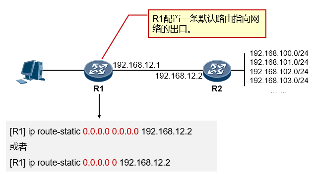
- Default route is also known as the default route, which is a 0.0.0.0.0.0 or 0.0.0/0 route, where the network address and mask are both 0.
- This is a special route that matches any destination IP address. The next hop of the default route can be considered the device's Last Help Object, or the default gateway.
- When a network device forwards a message, If there is a routing table entry in the routing table that matches the IP address of the message destination (a non-default routing table entry), the message is forwarded using that table entry; if there is no specific routing table entry match, the message is forwarded using the default route; if neither a specific route matches nor a default route exists, the message is discarded.
Dynamic Routing
Dynamic Routing - Routes learned by routers through dynamic routing protocols
- When a router activates the ability of a dynamic protocol, the process of route learning is dynamically completed between routers.
View and troubleshoot
Ping - Test Network Connectivity
Tracert - Tracks IP addresses for each hop along the way to the destination node
display ip routing-table - view routing table
display ip interface brief - interface summary information
Linux Routing Table
Linux uses the route-n command below to view the Linux kernel routing table.
# route -n
Kernel IP routing table
Destination      Gateway         Genmask         Flags Metric Ref    Use Iface
0.0.0.0(default) 192.168.1.1     0.0.0.0         UG    0      0        0 eth0
192.168.1.0      0.0.0.0(*)      255.255.255.0   U     0      0        0 eth0
211.140.188.188  192.168.1.1     255.255.255.255 UGH   0      0        0 eth0
| Output Item | Explain |
|---|---|
| Destination | Destination in the default route is 0.0 for the target segment or host. 0.0, also represented by default |
| Gateway | Gateway address, also known as next hop in routers, 0.0. 0.0 indicates that the destination is the network to which the host belongs, does not require routing, and'*'also indicates that the Gateway for direct-connect routing is 0.0. 0.0 |
| Genmask | Network mask, Genmask for default route is 0.0. 0.0 |
| Flags | Mark. |
| U - Routes are active | |
| G-Route Pointing Gateway | |
| R - Restore table entries generated by dynamic routing | |
| D - Installed dynamically by the routing daemon | |
| M - Modified by the routing daemon | |
| !- Deny Routing | |
| Metric | Routing distance, the number of transits required to reach the specified network (not used in the linux kernel) |
| Ref | Number of routing item references (not used in linux kernel) |
| Use | Number of times this routing item was looked up by routing software |
| Iface | The output interface corresponding to the routing table entry |
Routing Type
Host Routing
Host routing is a routing record in the routing table that points to a single IP address or host name. The Flags field of the host routing is H. For example, in the following example, the local host passes through IP address 192.168. 1.1 router arrives at IP address 10.0. 0.10 host.
Destination     Gateway         Genmask         Flags Metric Ref    Use Iface
10.0.0.10       192.168.1.1     255.255.255.255 UH   0      0        0 eth0
network route
A network route is a network that represents what a host can reach. The Flags field of the network route is N. For example, in the following example, the local host will be sent to Network 192.19. 12.0 packet forwarding to IP address 192.168. 1.1 router.
Destination     Gateway         Genmask         Flags Metric Ref    Use Iface
192.19.12.0     192.168.1.1     255.255.255.0   UN    0      0        0 eth0
Default Route
When the host cannot find the IP address or network route of the target host in the routing table, the packet is sent to the default route (default gateway). The Flags field of the default route is G. For example, in the following example, the default route is a router with IP address 192.168.1.1.
Destination     Gateway         Genmask         Flags Metric Ref    Use Iface
default         192.168.1.1     0.0.0.0   		UG    0      0        0 eth0
route command uses
- Routes added to host
route add -host 192.168.1.2 dev eth0
route add -host 10.20.30.148 gw 10.20.30.40     #Add to 10.20. Gateway 30.148
- Routing added to the network
route add -net 10.20.30.40 netmask 255.255.255.248 eth0   #Add 10.20. 30.40 Network
route add -net 10.20.30.48 netmask 255.255.255.248 gw 10.20.30.41 #Add 10.20. 30.48 Network
route add -net 192.168.1.0/24 eth1
- Add Default Route
route add default gw 192.168.1.1
- Delete Route
route del -host 192.168.1.2 dev eth0:0
route del -host 10.20.30.148 gw 10.20.30.40
route del -net 10.20.30.40 netmask 255.255.255.248 eth0
route del -net 10.20.30.48 netmask 255.255.255.248 gw 10.20.30.41
route del -net 192.168.1.0/24 eth1
route del default gw 192.168.1.1
- Block a route
route add -net 224.0.0.0 netmask 240.0.0.0 reject
Linux system turns on routing forwarding
echo 1 > /proc/sys/net/ipv4/ip_forward
Routing Summary
Routing aggregation generally refers to route aggregation, which means to aggregate a set of routes into a single routing broadcast. The final result of routing aggregation and the most obvious benefit is to reduce the size of the routing table on the network, which also belongs to routing aggregation by default.
-
Route Aggregation, also known as route summary, is the aggregation of a regular set of routes into a single route to reduce the size of the routing table and optimize the utilization of device resources.
-
Routing pooling is always a very important network design idea. A pooled network design will make our network more optimized, route entries simpler, and network management simpler. Awareness of routing aggregation should always be maintained in network design and deployment.
-
Not only can static routes deploy route aggregation, but dynamic routing protocols also support route aggregation.

Accurate calculation of aggregated routes
Existing detailed routes: 172.16. 1.0/24 to 172.16. 31.0/24, calculated the most accurate summary route, 172.16. 0.0/19

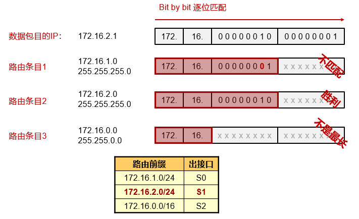
Maximum matching rule for routing lookup
When a router performs a lookup of destination IP addresses in a routing table, the principle used is the "longest matching principle". That is, it finds the table item with the longest matching degree between destination IP address and routing prefix, and uses the table item as the basis for final data forwarding.
- computing method
Instance Analysis
Example 1
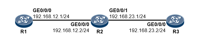
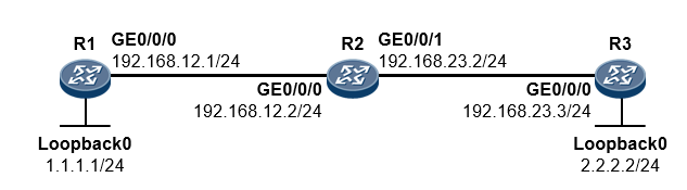
192.168 for R1. 12.1 Want to ping through 192.168 of R3. 23.2
# 1. R1 adds a static route with destination ip 192.168. The next jump on 23.0/24 is 192.168. 12.2
[R1] ip route-static 192.168.23.0 24 192.168.12.2
	 route add -net 192.168.23.0/24 eth1 gw 192.168.12.2
# 2. Packet arrives at R2, R2 discovery destination ip 192.168. 23.2 matches a direct-connect route in the routing table. Packets reach R3 through GE0/0/1 port. Can you ping through R3 at this time?
No!!!
Be careful:
Communication is bidirectional, so be aware of round-trip traffic.
Routes behave hop-by-hop, so you need to ensure that each router along the way has a route.
# 3. R3 returns return data, where the destination address of the packet is 192.168. 12.1, R3 doesn't know 192.168. Routes for 12.0/24 segments, so add the following routes in R3.
[R3] ip route-static 192.168.12.0 24 192.168.23.1
     route add -net 192.168.12.0/24 eth1 gw 192.168.23.1
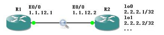
Example 2
Complete the configuration of three routers, making 1.1. 1.1 has access to 2.2. 2.2. (Loopback interface, also known as loopback interface, is a logical, virtual interface that simulates the direct connection segment of a router and can be used for testing)
# 1.1.1.1 -> 2.2.2.2
[R1] ip route-static 2.2.2.0 24 192.168.12.2    route add -net 2.2.2.0/24 eth1 gw 192.168.12.2
[R2] ip route-static 2.2.2.0 24 192.168.23.3	route add -net 2.2.2.0/24 eth1 gw 192.168.23.3

# 2.2.2.2 -> 1.1.1.1
[R3] ip route-static 1.1.1.0 24 192.168.23.2	route add -net 1.1.1.0/24 eth1 gw 192.168.12.2
[R2] ip route-static 1.1.1.0 24 192.168.12.1	route add -net 1.1.1.0/24 eth1 gw 192.168.12.1
Extend knowledge
Difference of Three Writing Methods for Static Routing
Static routes in Ethernet are typically written in the following ways:
- Next hop: ip route 2.2.2.0 255.255.255.0 1.1.12.2
R1 goes to 2.2. Route of 2.0/24, next hop is 1.1. 12.2, so you need to know 1.1. 12.2 mac address for subsequent packet encapsulation. So first the ARP broadcast requests the next hop's mac address, then receives the unicast reply from the opposite arp, and then R1 is either ping 2.2.2.1 or 2.2. 2.2, etc., are just the normal interaction process of ICMP packets, no longer need ARP broadcasting. - Out interface: ip route 2.2.2.0 255.255.255.0 e0/0
R1 goes to 2.2. The route of 2.0/24, coming out of the e0/0 interface, means that R1 considers this route to be a direct connection segment. This means R1 and 2.2. 2.1 Communications, need to go out from e0/0 port first get 2.2. mac address of 2.1 for subsequent packet encapsulation. So first is ARP broadcast request 2.2. mac address of 2.1, and then the process of receiving unicast replies from the opposite arp. Then R1 ping 2.2.2.1, is the normal interaction process of ICMP packets. So similarly, R1 and 2.2. 2.2 Communications, also need to go out from e0/0 port to get 2.2 first. 2.2 mac address for subsequent packet encapsulation. So this is another ARP broadcast request 2.2. mac address of 2.2, then receive unicast reply from arp. Then R1 ping 2.2.2.2 is also the normal interaction process for ICMP packets. R1 and 2.2. 2.3, 2.2. 2.4 Communications. - Next Jump+Out Interface: ip route 2.2.2.0 255.255.255.0 e0/0 1.1.12.2
The normal communication process is actually the same as 1.
Difference:
- Static Routing Next Hop: One (arp request/reply) + N (data communication)
- Static Routing Out Interface: N (arp request/reply+data communication)
- Static Routing Next Jump+Out Interface: One (arp request/reply) + N (data communication)
Advantages and disadvantages:
- Static routing next hop: ARP consumes less at one time, but if the next hop hangs, it will not work.
- Static Routing Out Interface: ARP consumes a lot of time, but has relatively many possible next hops and is redundant.
- Static Routing Next Hop+Out Interface: Relatively combines two advantages.
Linux Policy Routing
The routing rules mentioned earlier are based on the routing rules set for matching based on the destination IP address, while policy routing is more flexible. Linux can configure a number of policies. Packets pass through each policy in turn. Once a policy is matched, the corresponding routing table of the policy is further applied. If the current routing table cannot match the route, subsequent policy matching continues.
Looked for a very image from the Internet:

Policy Routing Appearance
Use ip rule show to view the contents of the policy database, which is the routing rule used by the current system
[root@localhost /]# ip rule show
0: from all lookup local
32765: from 135.105.115.149 lookup 231
32766: from all lookup main
32767: from all lookup default
Policy routing consists of three parts:
- Par1: The lower the number, the higher the priority, which is 0, 32766, 32767 in the figure above.
- part2: condition, such as from all, from 135.105.115.149
- part3: operations, such as lookup main, lookup 231
To sum up: 32765: from 135.105.115.149 lookup 231 means that the source address is 135.105. 115.149 IP packets, routed according to Routing Table 231.
How Routing Policy works
How does rule and table work together? It traverses in order of priority until the next jump is made
For example, an IP message source address is 135.105. 115.180, destination address 155.18. 49.20
- Find the local routing table, where the longest matching rule cannot find a route based on the destination address
- It further determines that route policy route 32765, whose source address is 135.105. 115.149, go to Table 231. Dissatisfaction.
- Then, 32766 is judged, and the condition of the routing policy is from all satisfied. Find the routing table main, where the next hop can be found and the IP packet forwarded.
iproute tool use
Commands such as ifconfig and route were often used to manage the network of Linux systems in the early days, but these tools could not be used for powerful policy-based routing mechanisms. Instead, the tool is IP route, which is installed by default on our Linux systems and can be checked by the ip-V command to see if the tool is installed
[root@localhost /]# ip -V
ip utility, iproute2-ss181023
Routing table management
The route command described earlier can only operate on a specific routing table, but in policy-based routing, there are multiple routing tables at the same time, so the route command will no longer be applicable and will instead use the ip command to manage the routing table
1. View Routing Table Contents
- Use ip rule show or cat/etc/iproute2/rt_ The tables command to see which routing tables are currently in use
- Use the ip route show [table id | name] command to view the contents of the routing table
[root@localhost /]# ip rule show
0: from all lookup local
32766: from all lookup main
32767: from all lookup default
[root@localhost /]# cat /etc/iproute2/rt_tables
#
# reserved values
#
255     local
254     main
253     default
0       unspec
#
# local
#
#1      inr.ruhep
[root@localhost /]# ip route show table main
192.168.1.0/24 dev eth0 proto kernel scope link src 192.168.1.1
192.168.2.0/24 dev eth1 proto kernel scope link src 192.168.2.1
default via 192.168.1.254 dev eth0
By default, the Linux system creates four routing tables that function as follows:
-
System Retention Table: table id 0
-
Local:table id 255, local routing table has local interface address, broadcast address, and NAT address. This table is automatically maintained by the system and cannot be manipulated by an administrator.
-
Main:table id 254, the main routing table. The routing table you see with the traditional command route -n is the main content. Linux systems use the contents of this routing table by default to transfer packets. Normally, as long as the network settings of the network card are configured, the contents of the main routing table are automatically generated.
As shown in the figure above,
- Because we have eth0 and eth1 network cards on our devices, and their IP settings are 192.168. 1.1/24 and 192.168. 2.1/24, so the first line in the routing table tells the system that if there are any packets to send to 92.168. 1.0/24 This segment sends packets directly from the eth0 interface, while the IP near this segment is 192.168. 1.1, the same is true for line 2; These two lines are the routes that will be generated by default as long as the IP on the computer network card is set and the network service is restarted, without special settings, similar to direct routes in routers.
- The last line is the default route, meaning if the packet is not sent to 192.168. 1.0/24 and 192.168. When the network segment is 2.0/24, the packets will be forwarded uniformly to 192.168. 1.254 hosts (typically routers) handle this, while 192.168.1.254 is the default gateway we set in our network configuration.
-
Default:table id 253, the default routing table whose contents are empty by default, in which default routes can generally be added.
2. Add Routes
Use the ip route add command to add routes to the desired routing table. The route command adds routes to the main table by default. The ip command does not specify a routing table and adds routes to the main table by default.
[root@localhost /]# ip route show table main
192.168.1.0/24 dev eth0 proto kernel scope link src 192.168.1.1
192.168.2.0/24 dev eth1 proto kernel scope link src 192.168.2.1
[root@localhost /]# ip route add default via 192.168.1.254 table 254
[root@localhost /]# ip route add 192.168.3.0/24 via 192.168.1.1 table main
[root@localhost /]#
[root@localhost /]# ip route show table main
default via 192.168.1.254 dev eth0
192.168.1.0/24 dev eth0 proto kernel scope link src 192.168.1.1
192.168.2.0/24 dev eth1 proto kernel scope link src 192.168.2.1
192.168.3.0/24 via 192.168.1.1 dev eth0
3. Delete Routes
Use the ip route del command to delete routes. If you do not specify a routing table, the middle route entry for the main routing table is deleted by default.
[root@localhost ~]# ip route show table 10
192.168.1.0/24 dev virbr0 scope link
default via 192.168.1.254 dev eth1
[root@localhost ~]#
[root@localhost ~]# ip route del default table 10
[root@localhost ~]#
[root@localhost ~]# ip route show table 10
192.168.1.0/24 dev virbr0 scope link
[root@localhost ~]#
[root@localhost ~]# ip route del 192.168.1.0/24 table 10
[root@localhost ~]#
[root@localhost ~]# ip route show table 10
[root@localhost ~]#
Rule Management
1. View Rules
Use ip rule show to view the contents of the policy database, which is the routing rule used by the current system
[root@localhost /]# ip rule show
0: from all lookup local
32766: from all lookup main
32767: from all lookup default
2. Add Rules
When you add a rule, you must first determine the condition, priority, and routing table ID before you can perform the add rule operation.
-
Conditions: Conditions are used to determine which types of packets can comply with this rule, and the fields available for matching are Source IP, Destination IP, Type of Service, fwmark, dev, and so on, which are used as follows
- Source IP: Determines which routing table a packet refers to to send out based on the source IP.
The following two examples show that if the source-side IP of a packet is 192.168. 1.10, for reference route table 10; If the source IP is 192.168. IP for 2.0/24 segments, refer to Routing Table 20
[root@localhost /]# ip rule add from 192.168.1.10 table 20
[root@localhost /]# ip rule add from 192.168.2.0/24 table 10
[root@localhost /]# ip rule show

[root@localhost /]# ip route show table 10
[root@localhost /]#
#Routing table 10 is not visible at this time because no routes have been added to table 10
[root@localhost /]# ip route add 192.168.1.0/24 dev eth1 table 10
[root@localhost ~]# ip route add default via 192.168.1.254 table 10
[root@localhost ~]# ip route show table 10
192.168.1.0/24 dev eth1 scope link
default via 192.168.1.254 dev eth1
- Destination IP: Determines which routing table a packet refers to to send out based on the destination IP.
The following two examples show that if the destination IP of a packet is 168.95. 1.1, for reference route table 10; If the destination IP is 168.95. IP for 0.0/24 segments, refer to Routing Table 20
 [root@localhost /]# ip rule add to 168.95.1.1 table 10
 [root@localhost /]# ip rule add to 168.96.0.0/24 table 20
- dev: Use the interface of data package input as the basis for judgment.
We want all packets sent by the eth2 interface to be forwarded by the eth0 interface and all packets sent by the eth3 interface to be forwarded by the eth1 interface. The following combinations of commands will meet our requirements
 [root@localhost /]# ip rule add dev eth2 table 1
 [root@localhost /]# ip rule add dev eth3 table 3
- Source IP: Determines which routing table a packet refers to to send out based on the source IP.
-
Priority
The preceding section describes how to use conditions in rules, and the next section discusses priority. Priorities are represented by numbers and range from 0 to 400 million. When adding a rule, if there is no special priority setting, the priority decreases by default from 32766, such as 32765, 32764.... If we need to set a special priority, we can add the prio XXX parameter at the end of the ip rule add command.
[root@localhost ~]# ip rule show
0: from all lookup local
32766: from all lookup main
32767: from all lookup default
[root@localhost ~]#
[root@localhost ~]# ip rule add from 192.168.1.0/24 table 1 prio 10
[root@localhost ~]# ip rule add from 192.168.2.0/24 table 2 prio 20
[root@localhost ~]#
[root@localhost ~]# ip rule show
0: from all lookup local
10: from 192.168.1.0/24 lookup 1
20: from 192.168.2.0/24 lookup 2
32766: from all lookup main
32767: from all lookup default
-
Routing table id: In policy-based routing on Linux, routing tables are represented by IDs.
Note: The following commands must be executed to refresh the routing buffer if the routing rules need to take effect immediately after they are created
[root@localhost ~]# ip route flush cache
3. Delete Rules
The ip command provides a flexible way to delete rules. For example, to delete rule 2 below, you can set the rules you want to delete by using either of the unique values of Priority, Conditions, and Routing Table, respectively, as follows:
[root@localhost ~]# ip rule show
0: from all lookup local
10: from 192.168.1.0/24 lookup 1
20: from 192.168.2.0/24 lookup 2
32766: from all lookup main
32767: from all lookup default
[root@localhost ~]# ip rule del prio 10
[root@localhost ~]# ip rule del from 192.168.1.0/24
[root@localhost ~]# ip rule del table 1
[root@localhost ~]# ip rule del from 192.168.1.0/24 table 1 prio 10
Instance Analysis
Our device is directly connected to 10.6 via a network cable. 124.0/24 network segment, device ip is 10.6. 124.206, Requires routing to be completed using your own configured routing policy
- Check the ip, rule and table of the current device
[root@localhost /]# ifconfig
eth0      Link encap:Ethernet  HWaddr 6E:1E:DC:7D:B2:28
          inet addr:10.6.124.203  Bcast:10.6.124.255  Mask:255.255.255.0
          inet6 addr: fe80::6c1e:dcff:fe7d:b228/64 Scope:Link
          UP BROADCAST RUNNING MULTICAST  MTU:1500  Metric:1
          RX packets:105989 errors:0 dropped:14985 overruns:0 frame:0
          TX packets:43 errors:0 dropped:0 overruns:0 carrier:0
          collisions:0 txqueuelen:1000
          RX bytes:70277805 (67.0 MiB)  TX bytes:3330 (3.2 KiB)
          Interrupt:199

lo        Link encap:Local Loopback
          inet addr:127.0.0.1  Mask:255.0.0.0
          inet6 addr: ::1/128 Scope:Host
          UP LOOPBACK RUNNING  MTU:65536  Metric:1
          RX packets:0 errors:0 dropped:0 overruns:0 frame:0
          TX packets:0 errors:0 dropped:0 overruns:0 carrier:0
          collisions:0 txqueuelen:1
          RX bytes:0 (0.0 B)  TX bytes:0 (0.0 B)

[root@localhost /]# ip rule show
0:      from all lookup local
32766:  from all lookup main
32767:  from all lookup default
[root@localhost /]# ip route show table main
10.6.124.0/24 dev eth0 scope link  src 10.6.124.203
- Under the existing rules, to and segment 10.6. 124.0/24 of the device network communication, the priority is 32766 rules, query is the main table;
For devices that are not in the eth0 direct connection segment, no matching entries can be found under the current rules, and the network is unreachable.
[root@localhost /]# ping 8.8.8.8
PING 8.8.8.8 (8.8.8.8): 56 data bytes
ping: sendto: Network is unreachable
[root@localhost /]# ip route get 8.8.8.8
ip: RTNETLINK answers: Network is unreachable
- Add rule with source IP address set to all, priority set to 8, query route table id set to 10
[root@localhost /]# ip rule add from all table 10 prio 8
-
Add a route,
Because the network cable is directly connected to eth0 for 10.6. 124.0/24 network segment, so this segment can communicate directly through the eth0 network card
For devices that are not in the eth0 direct connection segment, send to gateway 10.6. 124.254, forwarded outward by it for further routing
[root@localhost /]# ip route add 10.6.124.0/24 dev eth0 table 10
[root@localhost /]# ip route add default via 10.6.124.254 dev eth0 table 10
[root@localhost /]# ip route show table 10
default via 10.6.124.254 dev eth0
10.6.124.0/24 dev eth0 scope link
[root@localhost /]# ip rule show
0:      from all lookup local
8:      from all lookup 10
32766:  from all lookup main
32767:  from all lookup default
-
test
To test whether the network can communicate properly, ping my server 10.6. 124.15
Testing whether table 10 was used, matched to the destination address at 8.8. Routing entry for 8.8, indicating the use of table 10
[root@localhost /]# ip route flush cache
[root@localhost /]# ip route get 10.6.124.15
10.6.124.15 dev eth0  src 10.6.124.203
[root@localhost /]# ip route get 8.8.8.8
8.8.8.8 via 10.6.124.254 dev eth0  src 10.6.124.203