1.5 Route
Linux does not have a direct command brctl like creating a virtual Bridge, and it does not have an indirect command. It cannot create a virtual Router... Because it is a Router!
However, Linux does not turn on the routing and forwarding function by default. You can use this command to verify:
cat /proc/sys/net/ipv4/ip_forward
0
0 -- > indicates that the routing function is not enabled
1 -- > turn on the routing and forwarding function of Linux
Temporary modification (restart failure):
echo "1" /proc/sys/net/ipv4/ip_forward
1 /proc/sys/net/ipv4/ip_forward
Permanent modification:
vim /etc/sysctl.conf
net.ipv4.ip_forward=1
:wq!

load configuration
sysctl -p
net.ipv4.ip_forward = 1
Test case:
NS1/tap1 and NS2/tap2 are not in the same network segment. They need to be forwarded through a Router to communicate. The Router in the figure is a schematic diagram. In fact, Linux has enabled the routing forwarding function.
When we add a tap and bind an IP address to it, Linux will automatically generate a direct route.
(1) Create veth pair
ip link add tap2 type veth peer name tap2_peer
ip link add tap3 type veth peer name tap3_peer
(2) Create namespace
ip netns add ns1
ip netns add ns2
(3) Migrate tab to namespace
ip link set tap2 netns ns1
ip link set tap3 netns ns2
(4) Configure tap ip address
ifconfig tap2_peer 192.168.100.1/24
ifconfig tap3_peer 192.168.200.1/24
ip netns exec ns1 ifconfig tap2 192.168.100.2/24 up
ip netns exec ns2 ifconfig tap3 192.168.200.2/24 up
(5) Set tap to up
ip link set tap2_peer up
ip link set tap3_peer up
(6)ping (no connection)
ip netns exec ns1 ping 192.168.200.2
connect: Network is unreachable
Check the routing table
ip netns exec ns1 route

Kernel IP routing table
Destination     Gateway         Genmask         Flags Metric Ref    Use Iface
192.168.100.0   0.0.0.0         255.255.255.0   U     0      0        0 tap2
It can be seen from the above figure that ns1 does not reach the route 192.168.200.0/24. At this time, we need to add it manually,
(7) Both NS1 and NS2 add static routes to reach each other's network segments
ip netns exec ns1 route add -net 192.168.200.0 netmask 255.255.255.0 gw 192.168.100.1
ip netns exec ns2 route add -net 192.168.100.0 netmask 255.255.255.0 gw 192.168.200.1
(8) View the routing table again
ip netns exec ns1 route

Kernel IP routing table
Destination     Gateway         Genmask         Flags Metric Ref    Use Iface
192.168.100.0   0.0.0.0         255.255.255.0   U     0      0        0 tap2
192.168.200.0   192.168.100.1   255.255.255.0   UG    0      0        0 tap2
(9) ping it
ip netns exec ns1 ping 192.168.200.2

PING 192.168.200.2 (192.168.200.2) 56(84) bytes of data.
64 bytes from 192.168.200.2: icmp_seq=1 ttl=64 time=0.083 ms
64 bytes from 192.168.200.2: icmp_seq=2 ttl=64 time=0.034 ms
64 bytes from 192.168.200.2: icmp_seq=3 ttl=64 time=0.036 ms
^C
--- 192.168.200.2 ping statistics ---
3 packets transmitted, 3 received, 0% packet loss, time 1999ms
rtt min/avg/max/mdev = 0.034/0.051/0.083/0.022 ms
1.6 tun
tun is a network layer (IP) point-to-point device that enables IP layer tunneling. The three-tier tunnel supported by Linux natively can be viewed through the command line ip tunnel help:
ip tunnel help

Usage: ip tunnel { add | change | del | show | prl | 6rd } [ NAME ]
          [ mode { ipip | gre | sit | isatap | vti } ] [ remote ADDR ] [ local ADDR ]
          [ [i|o]seq ] [ [i|o]key KEY ] [ [i|o]csum ]
          [ prl-default ADDR ] [ prl-nodefault ADDR ] [ prl-delete ADDR ]
          [ 6rd-prefix ADDR ] [ 6rd-relay_prefix ADDR ] [ 6rd-reset ]
          [ ttl TTL ] [ tos TOS ] [ [no]pmtudisc ] [ dev PHYS_DEV ]

Where: NAME := STRING
       ADDR := { IP_ADDRESS | any }
       TOS  := { STRING | 00..ff | inherit | inherit/STRING | inherit/00..ff }
       TTL  := { 1..255 | inherit }
       KEY  := { DOTTED_QUAD | NUMBER }
The following are the three-tier tunnels that Linux natively supports

Test case:
Test diagram:
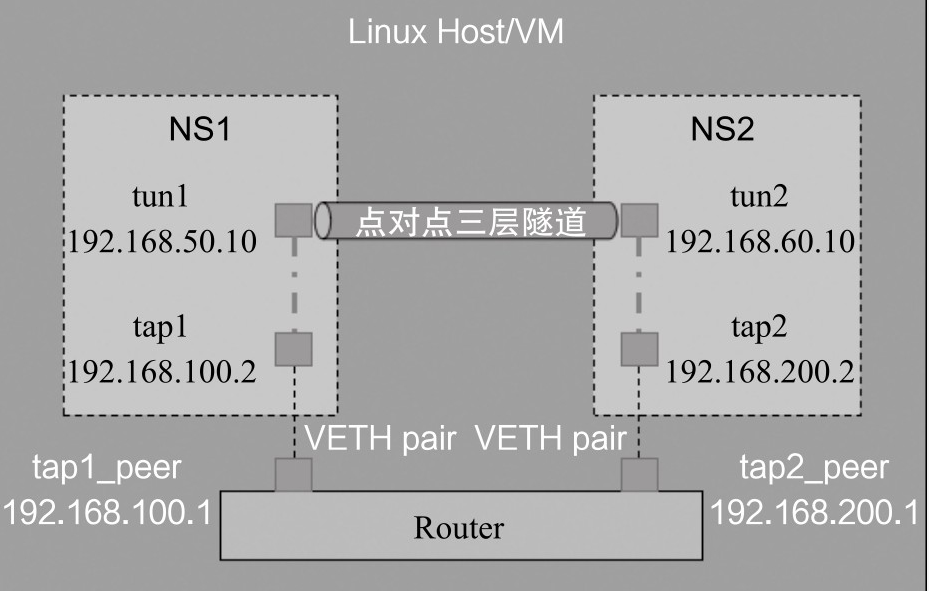
(1) The configuration of TAP1 and tap2 can be ping ed. I've done it above. It's not repeated here
(2) After tap1 and tap2 are connected, if tun1 and tun2 in Figure 2-10 are not considered as Tun devices temporarily, but as two "dead" devices (for example, as two network cards without any configuration), then tun1 and tun2 are like two isolated islands, which are not only disconnected from each other, but also have nothing to do with tap1 and tap2, as shown in the figure below
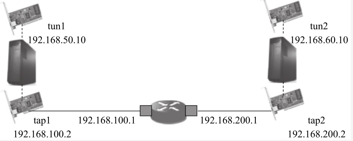
At this time, we need to configure tun1 and tun2 so that the two islands can communicate with each other. Let's take ipip tunnel as an example.
(3) Load the ipip module. Linux does not have this module by default
load
modprobe ipip

see
lsmod | grep ipip
ipip                   13465  0
tunnel4                13252  1 ipip
ip_tunnel              25163  1 ipip
(4) Create tun1 and ipip tunnel in ns1
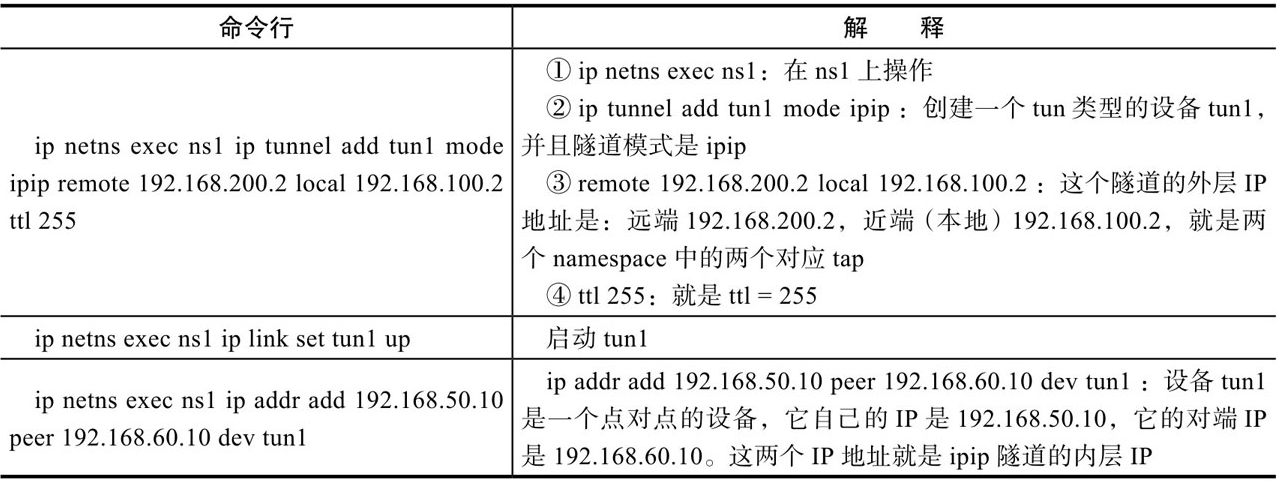
ip netns exec ns1 ip tunnel add tun1 mode ipip remote 192.168.200.2 local 192.168.100.2 ttl 255
ip netns exec ns1 ip link set tun1 up
ip netns exec ns1 ip addr add 192.168.50.10 peer 192.168.60.10 dev tun1
(5) Create tun1 and ipip tunnel in ns2
ip netns exec ns2 ip tunnel add tun2 mode ipip remote 192.168.100.2 local 192.168.200.2 ttl 255
ip netns exec ns2 ip link set tun2 up
ip netns exec ns2 ip addr add 192.168.60.10 peer 192.168.50.10 dev tun2
Command line interpretation:
(6)ping
ip netns exec ns1 ping 192.168.60.10

PING 192.168.60.10 (192.168.60.10) 56(84) bytes of data.
64 bytes from 192.168.60.10: icmp_seq=1 ttl=64 time=0.058 ms
64 bytes from 192.168.60.10: icmp_seq=2 ttl=64 time=0.046 ms
^C
--- 192.168.60.10 ping statistics ---
2 packets transmitted, 2 received, 0% packet loss, time 999ms
rtt min/avg/max/mdev = 0.046/0.052/0.058/0.006 ms
(7) Check
 ip netns exec ns1 ifconfig -a

tun1: flags=209<UP,POINTOPOINT,RUNNING,NOARP>  mtu 1480
        inet 192.168.50.10  netmask 255.255.255.255  destination 192.168.60.10
        tunnel   txqueuelen 1000  (IPIP Tunnel)
        RX packets 2  bytes 168 (168.0 B)
        RX errors 0  dropped 0  overruns 0  frame 0
        TX packets 2  bytes 168 (168.0 B)
        TX errors 0  dropped 0 overruns 0  carrier 0  collisions 0
tun1 is a port of an ipip tunnel. The IP is 192.168.50.10 and the opposite end is 192.168.60.10
(8) View routing table
ip netns exec ns1 route

Kernel IP routing table
Destination     Gateway         Genmask         Flags Metric Ref    Use Iface
192.168.60.10   0.0.0.0         255.255.255.255 UH    0      0        0 tun1
192.168.100.0   0.0.0.0         255.255.255.0   U     0      0        0 tap2
192.168.200.0   192.168.100.1   255.255.255.0   UG    0      0        0 tap2

Increased tun Equipment ns1 Routing table for
Summary: a direct route of the route to the destination 192.168.60.10 can go out from tun1
1.7 iptables
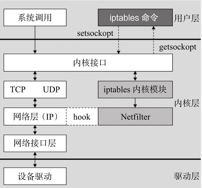
Iptables is different from tap/tun introduced earlier. It is not a network device. However, they have the same thing: they are all Linux software. Iptables can realize firewall, NAT and other functions, but this sentence is also right and wrong. To say it is right, we do realize the functions of firewall and Nat through the command line related to iptables. To say it is wrong, it is because iptables It is just a command-line tool running in user space. The netfilter module running in kernel space really realizes these functions. The relationship between them is shown in the figure below
(1)NAT
- NAT (Network Address
Translation, as the name suggests, is to convert from one IP address to another. Of course, the root cause is that the IP address is not enough (one solution to IP address exhaustion is IPv6 and the other is NAT). Therefore, what we basically do in NAT is the mutual conversion of public network addresses and private network addresses. If it is necessary to convert public network addresses or private network addresses, it is technically supported, but there are very few such scenarios. - From the perspective of implementation technology, NAT is divided into three schemes: static NAT, dynamic NAT and port multiplexing.
- Static NAT has two features (as shown in the figure below).
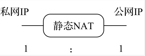
- The conversion rules between private IP address and public IP address are statically specified. For example, 10.10.10.1 and 50.0.0.1 convert each other. This is statically specified.
- The private IP address and the public IP address are 1:1, that is, a private IP address corresponds to a public IP address.
Dynamic NAT
- Generally, when the public IP address is less than the private IP address, the dynamic NAT scheme is used. If the public IP address is more (or equal) than the private IP address, the static NAT can be used. There is no need to be so troublesome.
- Dynamic NAT means that there is no fixed conversion relationship between a batch of private IP and public IP addresses, but the NAT module performs dynamic matching in the process of IP message processing. Although the public IP address is less than the private IP address, at the same time, the online private IP demand is less than or equal to the number of public IP, otherwise some private IP will not be correctly converted, resulting in network communication failure.
Dynamic NAT has three features (as shown in the figure below)

- The IP addresses of private network and public network are not fixed matching and conversion, but change;
- The conversion rules between the two are not statically specified, but dynamically matched;
- The distance between the private IP address and the public IP address is m: n, - generally m < n
(3) Port multiplexing / PAT
- If there are multiple private IP addresses and there is only one public IP address, then static NAT is obviously not working, and dynamic NAT is basically not working (only one public IP is not enough) At this time, port multiplexing is required. Multiple private network IPS are mapped to the same public network IP, and different private network IPS are distinguished by port numbers, which refer to TCP/UDP port numbers. Therefore, port multiplexing is also called PAT(Port Address Translation).
Port multiplexing (PAT) is characterized by (as shown in the figure below);
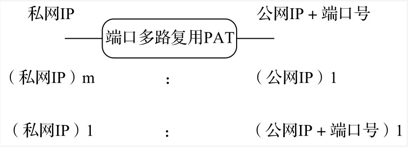
- Private IP: public IP = m: 1;
- Distinguish private IP by public IP + port number.
(4) SNAT/DNAT
- The previous topic is static nat (static)
NAT) and dynamic NAT. Unfortunately, SNAT and DNAT cannot be abbreviated for short, because SNAT/DNAT has another meaning and is another abbreviation. To distinguish between SNAT (source network address translation) and DNAT (destination network address translation), the two functions can be simply distinguished by who the connection initiator is. - When the internal address wants to access the services on the public network (such as Web access), the internal address will actively initiate the connection. The gateway on the router or firewall will perform an address conversion on the internal address to convert the private IP of the internal address into the public IP of the public network. This address conversion of the gateway is called SNAT, which is mainly used for internal shared IP access to the outside.
- When external services need to be provided internally (such as publishing Web sites externally) , the external address initiates an active connection, and the gateway on the router or firewall receives the connection, and then converts the connection to the internal. In this process, the gateway with public IP replaces the internal service to receive the external connection, and then performs address conversion internally. This conversion is called DNAT, which is mainly used for external publishing of internal services.
(2) NAT Chain in Netfilter
- It's a little too pedantic to say chain. In vernacular, it's time. We know from the previous introduction that NAT processes IP packets at three time points. Let's describe one by one.
(1)NAT-PREROUTING(DNAT)
The processing time of nat-provisioning (DNAT) is shown in the figure below
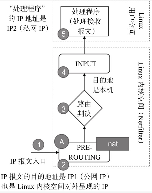
- The sequence of IP message flow is "1-2-3-4-5" in Figure 2-21. NAT processing is performed at A in Figure 2-21, that is, the preouting time point. The destination address of IP message is IP1 (public network IP), which is the IP address presented to the outside (public network) in Linux kernel space (indicating that there can be multiple such IP addresses). When the message reaches the time point of preouting, the NAT module will process it. If necessary (i.e. relevant NAT configuration is made in advance), the NAT module will convert the destination IP from IP1 to IP2 (this is configured in advance), which is the so-called DNAT.
(3)NAT-PREROUTING(SNAT)
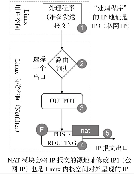
- The sequence of IP message flow is "1-2-3-4-5" in the figure. NAT processing is performed at "E" in the figure, that is, the POSTROUTING time point. The source address of the IP message is IP3 (private network lP). When the message finally passes through the time point of POSTROUTING, if necessary (i.E. relevant NAT configuration is made in advance), the NAT module will process it. The NAT module will convert the source IP from IP3 to lP1 (this is configured in advance), which is the so-called SNAT. This IP1 is the IP address presented to the outside (public network) in the Linux kernel space (note that there can be multiple such lP addresses.).
(4)NAT-OUTPUT(DNAT)
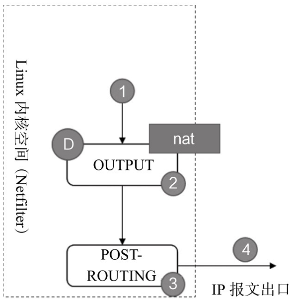
(5) Summary
There are three chains (processing time points) for NAT processing of Netfilter module in Linux kernel space, as shown in the figure below:

(6)Firwwall
The firewall concept in iptables belongs to the concept of network firewall, as shown in the following figure:
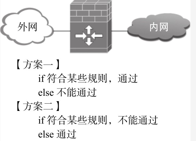
"Some" rules in the figure determine whether they belong to "network" firewall. These rules of firewall in iptables are rules based on TCP/IP protocol stack, so we call them network firewall. These rules include:
-
In interface (in network interface name), which network interface the data packet enters from;
-
Out interface (network interface name), which network interface the data packet is output from;
-
Protocol (protocol type), protocol of data packet, such as TCP, UDP, ICMP, etc;
-
Source (source address (or subnet)), the source IP address (or subnet) of the packet;
-
Destination (destination address (or subnet)), the destination IP address (or subnet) of the packet;
-
sport (source port number), the source port number of the packet;
-
dport (destination port number), the destination port number of the packet.
Those meeting these rules can be set to pass (ACCEPT), otherwise, they will not pass (DROP). Or, those meeting these rules will be set to fail (DROP); otherwise, they will pass (ACCEPT).
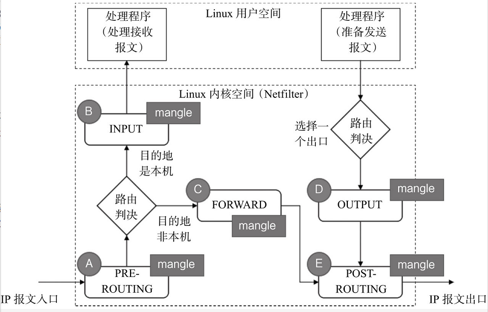
(7)mangle
The mangle table is mainly used to modify the TOS (type of service), TTL (time to live) and set Mark marks for packets to realize QoS(Quality of Service) adjustment, policy routing and other applications.
The time point of mangle processing in netfilter module is shown in the following figure:
(processing time point of Mangle in Netfilter)
Summary of network virtual infrastructure
tap, tun and veth pair are all called devices in Linux, but they are often called interfaces in analogy with everyday concepts. Neutron uses these "interfaces" to connect bridges, bridges to VM S (virtual machines) and bridges to routers. The comparison between the three and physical network cards is shown in the figure below.
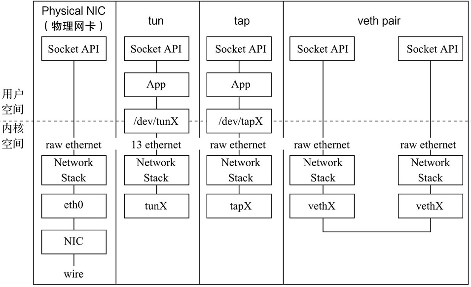
- Instead, router and bridge, which are not called devices in Linux, are often called devices in daily concepts. Bridge provides layer-2 forwarding function, and router provides layer-3 forwarding function. Router also often provides SNAT/DNAT function with iptable. Bridge also often provides Firewall function with iptable.
- In Neutron, isolation is a very important feature, and using namespace for isolation is also a very important means of Neutron.