
Introduction: The MPU9250 from Longqiu was preliminarily tested using esp32 micropathon.
Key words: MPU9250, I2C, ESP32, software I2C
§01 MPU9250
there are several on hand from last semester MPU9250 sensor of Longqiu , in order to use it to do experiments in the future, the esp32 micro Python experimental board is used to test it.
1, Basic information
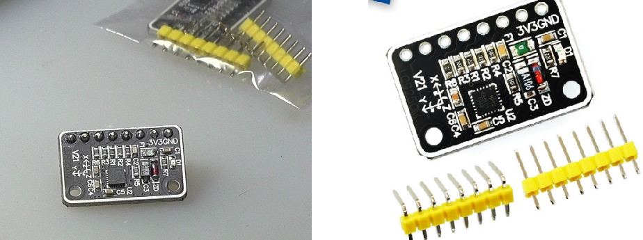
according to MPU9250 TB web page This module is a nine axis IMU. The word "MP92" is displayed on the silk screen of the chip.
1. Chip information
MPU9250 nine axis product manual in Chinese : https://max.book118.com/html/2017/0906/132114737.shtm You can know the basic information of this module:
- Working voltage: 3.3V;
- Programming interface: SPI, I2C
2. Module interface
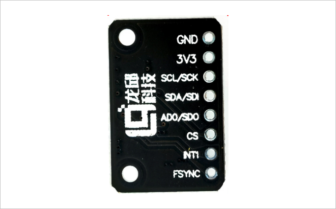
| Serial number | name | function |
|---|---|---|
| PIN1 | GND | Power ground |
| PIN2 | 3V3 | 3.3V power supply |
| PIN3 | SCL/SCK | I2C/SPI clock signal |
| PIN4 | SDA/SDI | I2C data signal; SPI data input |
| PIN5 | AD0/SDO | I2C address selection (1101001); SPI data output |
| PIN6 | CS | Chip Select |
| PIN7 | INT1 | Terminal digital output signal |
| PIN8 | FSYNC | Digital synchronous input frame, if different, grounded |
(1) I2C interface
I2C address: AD0=0: 1101000AD0=1: 1101001
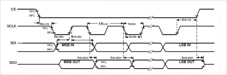
(2) SPI interface
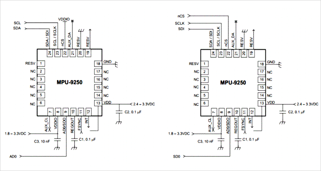
the following is the selection of different interface forms of the chip:
- nCS connected to high level: I2C bus;
- nCS connected to low level: SPI bus;
2, Power on test
1. Interface pull-up resistance
use a multimeter to measure the resistance between the CLK, SDK and 3.3V of the module, which is 10k Ω, which indicates that R4 and R5 (10k Ω) are internally used in the module, and the pull-up resistance is used to bias the SDK and CLK.
2. Port configuration
MP9255 module port: A0: GNDCS: 3.3V
FSYNC: GND
INT: NULL
§ 02 ESP32 test
1, Basic test
1. Pin configuration
according to Micropathon esp32 manual For software I2C configuration in, any pin of ESP32 can be used as I2C pin.
according to Design and implementation of ESP32-S module adapter board For the description of ESP32 adapter module, the rightmost two pins of PIO are used as I2C joints respectively.
ESP32I2C pin: SCL: IO2SDA: IO15
◎ note: when rxd2 and txd2 are used as SCL of I2C, SDA will output low level, and the reason is unknown.
2. Scanning equipment
scan I2C equipment, you can obtain: [104]: 0b1101000
from machine                import Pin,Timer,SoftI2C
import time
import math

led0 = Pin(5, Pin.OUT)
led1 = Pin(18, Pin.OUT)

i2c = SoftI2C(scl=Pin(16), sda=Pin(17), freq=100000)
scan = i2c.scan()

print(scan)
print('Begin ...')

while True:
    led0.on()
    led1.off()
    time.sleep_ms(200)
    led0.off()
    led1.on()
    time.sleep_ms(200)
2, Read data
in Detailed functions of MPU9250 The detailed process of MPU9250 interface reading and writing is given. MPU9250 data book Download link.
#!/usr/local/bin/python
# -*- coding: gbk -*-
#============================================================
# TEST1.PY                     -- by Dr. ZhuoQing 2021-09-20
#
# Note:
#============================================================
from machine                import Pin,Timer,SoftI2C
import time
import math
led0 = Pin(5, Pin.OUT)
led1 = Pin(17, Pin.OUT)
i2c = SoftI2C(scl=Pin(2), sda=Pin(15), freq=100000)
#------------------------------------------------------------
MPU9250_ADDRESS            = 0x68
MAG_ADDRESS                = 0x0c
GYRO_FULL_SCALE_250_DPS    = 0x00
GYRO_FULL_SCALE_500_DPS    = 0x08
GYRO_FULL_SCALE_1000_DPS   = 0x10
GYRO_FULL_SCALE_2000_DPS   = 0x18
ACC_FULL_SCALE_2_G        = 0x00
ACC_FULL_SCALE_4_G        = 0x08
ACC_FULL_SCALE_8_G        = 0x10
ACC_FULL_SCALE_16_G       = 0x18
#------------------------------------------------------------
def MPU9250Setup():
    i2c.writeto_mem(MPU9250_ADDRESS, 27, bytearray(GYRO_FULL_SCALE_2000_DPS))
                                    # Configure gyroscope range
    i2c.writeto_mem(MPU9250_ADDRESS, 28, bytearray(ACC_FULL_SCALE_16_G))
                                    # Configure accelerometer range
    i2c.writeto_mem(MPU9250_ADDRESS, 0x37, bytearray(0x2))
                                    # Set by pass mode for magnetometer
#    time.sleep_ms(10)
#    i2c.writeto_mem(MAG_ADDRESS, 0x0a, bytearray(0x16))
                                    # Request first magnetometer single measurement
#------------------------------------------------------------
def MPU9250read():
    buf = bytearray(14)
    buf = i2c.readfrom_mem(MPU9250_ADDRESS, 0x3b, 14)
    ax = int.from_bytes(buf[0:2], 'big', True)
    ay = int.from_bytes(buf[2:4], 'big', True)
    az = int.from_bytes(buf[4:6], 'big', True)
    gx = int.from_bytes(buf[8:10], 'big', True)
    gy = int.from_bytes(buf[10:12], 'big', True)
    gz = int.from_bytes(buf[12:14], 'big', True)
    temp = int.from_bytes(buf[6:8], 'big', True)
    return (ax,ay,az),(gx,gy,gz), temp
#------------------------------------------------------------
MPU9250Setup()
print(MPU9250read())
#------------------------------------------------------------
while True:
    led0.on()
    led1.off()
    time.sleep_ms(200)
    led0.off()
    led1.on()
    time.sleep_ms(200)
    print(MPU9250read())
#------------------------------------------------------------
#        END OF FILE : TEST1.PY
#============================================================
※ test conclusion ※
tested the I2C bus function of ESP32 software. ESP32 is used to read the acceleration of MPU9250 and the data of gyroscope.
remaining problems: problems encountered when reading magnetometer data. The magnetometer data cannot be accessed correctly.
■ links to relevant literature:
- MPU9250 sensor of Longqiu
- MPU9250 nine axis product manual in Chinese
- Micropathon esp32 manual
- Design and implementation of ESP32-S module adapter board
- Detailed functions of MPU9250
- MPU9250 data book
- MPU9250 register manual, English original
● relevant chart links:
- Figure 1.1.0 MPU9250 module
- Figure 1.1.1 module interface
- Table 1-1-1 module interface
- Figure 1.1.2 SPI interface timing characteristics
- Figure 1.1.3 configuration of two different interfaces
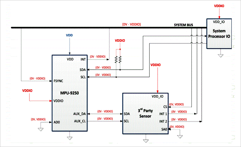
- Figure 1.1.4 I2C bus usage mode
- Figure 1.2.1 configuring module ports
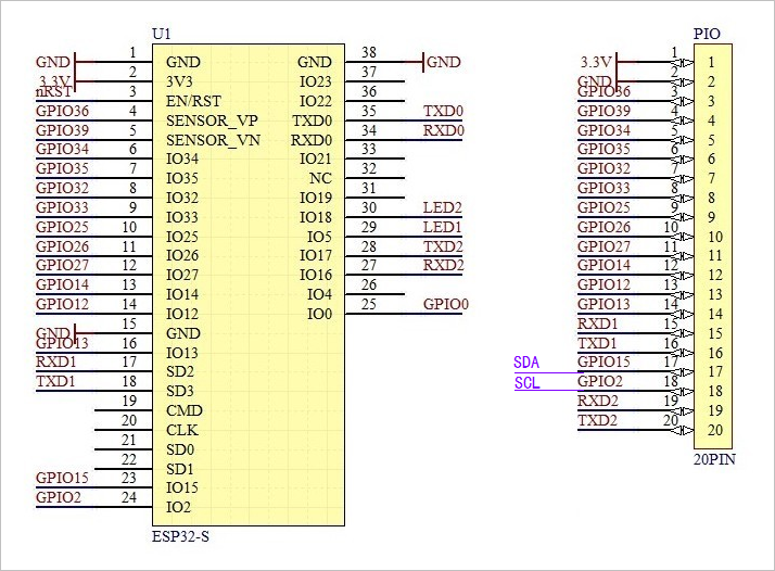
- Figure 2.1.1 I2C pin configuration
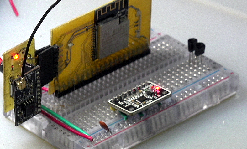
- Figure 2.1.2 connecting I2C pin