summary
S32K1 has rich Timer resources. Today, we start with the simplest LPIT.
LPIT: low power periodic interrupt timer.
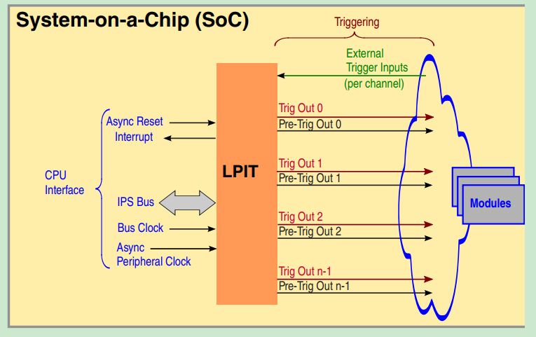
LPIT is a periodic interrupt timer with multiple timer channels. When a timer reaches the programmed count value, the corresponding channel will generate pre trigger and trigger output signals, which can trigger other modules on MCU. Each channel can be cascaded to form a larger timer. Depending on the timer mode, when the count value is reached, the channel can overload the count or stop.
To learn more, visit S32K1 column.
Timer mode
The Timer of each channel can be configured in compare or capture mode.
Comparison mode: each timer channel can be started, overloaded and restarted through the control bit. The Timer can be configured to decrease from the programmed starting value, or from the selected trigger input and the timeout of the previous channel.
Capture mode: the timer can be used to perform measurements and capture the timer value when the selected trigger input assertion. The timer can support one or more measurements (such as frequency measurement).
Timer feature
• each channel contains a 32-bit counter loading start value to count down the rising edge of each peripheral clock.
• after reaching zero (channel timer timeout), a trigger output will be generated.
• counter enable uses the timer enable register control bit, external or internal trigger, or through the previous channel timeout (when timer link is used)
• after the channel timer times out, an interrupt bit will be set to inform the CPU that the timer times out.
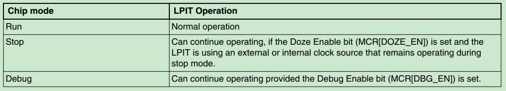
Different operation modes
Chip specific characteristics
S32K1xx contains an LPIT module with 4 channels, which is not supported in Low leakage mode and Wait mode. chn0-3 of LPIT can trigger DMAchn0-3 event periodically. LPIT is designed to capture small pulses at its input trigger regardless of its clock frequency. However, for reliable operation, these triggers shall be separated by at least 10 LPIT bus clock cycles. LPIT can be used as an alternative ADC hardware trigger source, which is realized through TRGMUX. Each LPIT channel supports one pre trigger and one pre triggers. The LPIT channel is implemented based on independent counters. When used as ADC trigger source, channel output generates ADC hardware trigger and pre trigger.
The value read by CVALn at run time is unreliable. If you want to read it, read it in ISR.
Memory mapping
/** LPIT - Register Layout Typedef */
typedef struct {
  __I  uint32_t VERID;       /**< Version ID Register, 0x0 */
  __I  uint32_t PARAM;       /**< Parameter Register, 0x4 */
  __IO uint32_t MCR;         /**< Module Control Register, 0x8 */
  __IO uint32_t MSR;         /**< Module Status Register, 0xC */
  __IO uint32_t MIER;        /**< Module Interrupt Enable Register, 0x10 */
  __IO uint32_t SETTEN;      /**< Set Timer Enable Register, 0x14 */
  __IO uint32_t CLRTEN;      /**< Clear Timer Enable Register, 0x18 */
       uint8_t RESERVED_0[4];
  struct {
    __IO uint32_t TVAL;        /**< Timer Value Register,  0x20,  0x10 */
    __I  uint32_t CVAL;        /**< Current Timer Value,  0x24,  0x10 */
    __IO uint32_t TCTRL;       /**< Timer Control Register,  0x28,  0x10 */
         uint8_t RESERVED_0[4];
  } TMR[LPIT_TMR_COUNT];
} LPIT_Type, *LPIT_MemMapPtr;
DBG_EN: 1b - Allow timer channels to continue to run in Debug mode
DOZE_EN: 1b - Allow timer channels to continue to run in DOZE mode
SW_RST: 1b - Reset timer channels and registers
        Before clearing the Software Reset bit, software must wait for 4 peripheral clocks
M_CEN: 1b - Enable peripheral clock to timers


TIFn: Channel n Timer Interrupt Flag

TIEn: Channel n Timer Interrupt Enable

SET_T_EN_n: Set Timer n Enable

CLR_T_EN_n: Clear Timer n Enable
TCTRL:
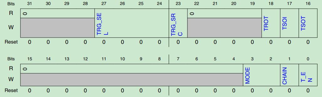
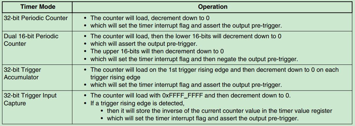
T_EN: Timer Enable
CHAIN: Chain Channel,channel will decrement when timer channel N-1 trigger asserts
MODE:
	00b - 32-bit Periodic Counter
	01b - Dual 16-bit Periodic Counter
	10b - 32-bit Trigger Accumulator
	11b - 32-bit Trigger Input Capture
TSOT: Timer Start On Trigger
	Timer starts to decrement when a rising edge on a selected trigger is detected
TSOI: Timer Stop On Interrupt
	1b - The channel timer will stop after a timeout
TROT: Timer Reload On Trigger
	1b - Timer will reload on the selected trigger
TRG_SRC:
	0b - Selects external triggers
	1b - Selects internal triggers
TRG_SEL:
	0000-0011b - Timer channel 0 - 3 trigger source is selected
Function description
Initialization
Timer Modes
Channel Chaining
Detailed timing
To learn more, visit S32K1 column.