Test pm (sleep management) function with 724 development board
brief introduction
When using the module, we often pay attention to the power consumption of the module. This example teaches you how to use the 724 development board to test the sleep management function of the module
stores reserve
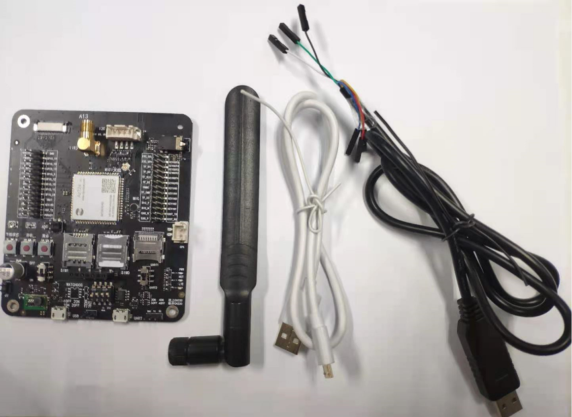
- EVB_Air724UG_A13 A set of development board, including DC power supply, USB cable, serial port cable and DuPont cable
- A computer, serial port debugging tool (sscom 5.13.1 is used here), Luatools_2.1.5
- luat development environment: Environment construction method
pm function introduction
This is the portal of power management. Please click me
API description
This is the portal introduced by pm interface. Please click me
step
We will make two demonstrations here. The first is to see the current when the module is dormant (this is the only way to judge whether the module is dormant). The second is to see the impact of dormancy on the function of the module
The development board I use has removed the peripheral devices that affect power consumption, such as led lights and serial port chips
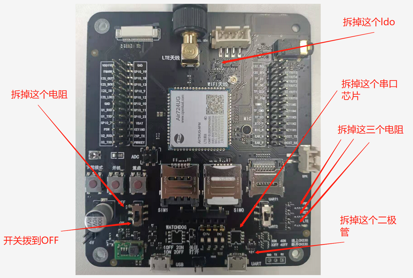
First example
Use the development board with peripheral devices removed to burn the demo of pm, and use the precision power supply to test the average power consumption of 5 minutes during sleep and wake-up after the module is normally connected to the network
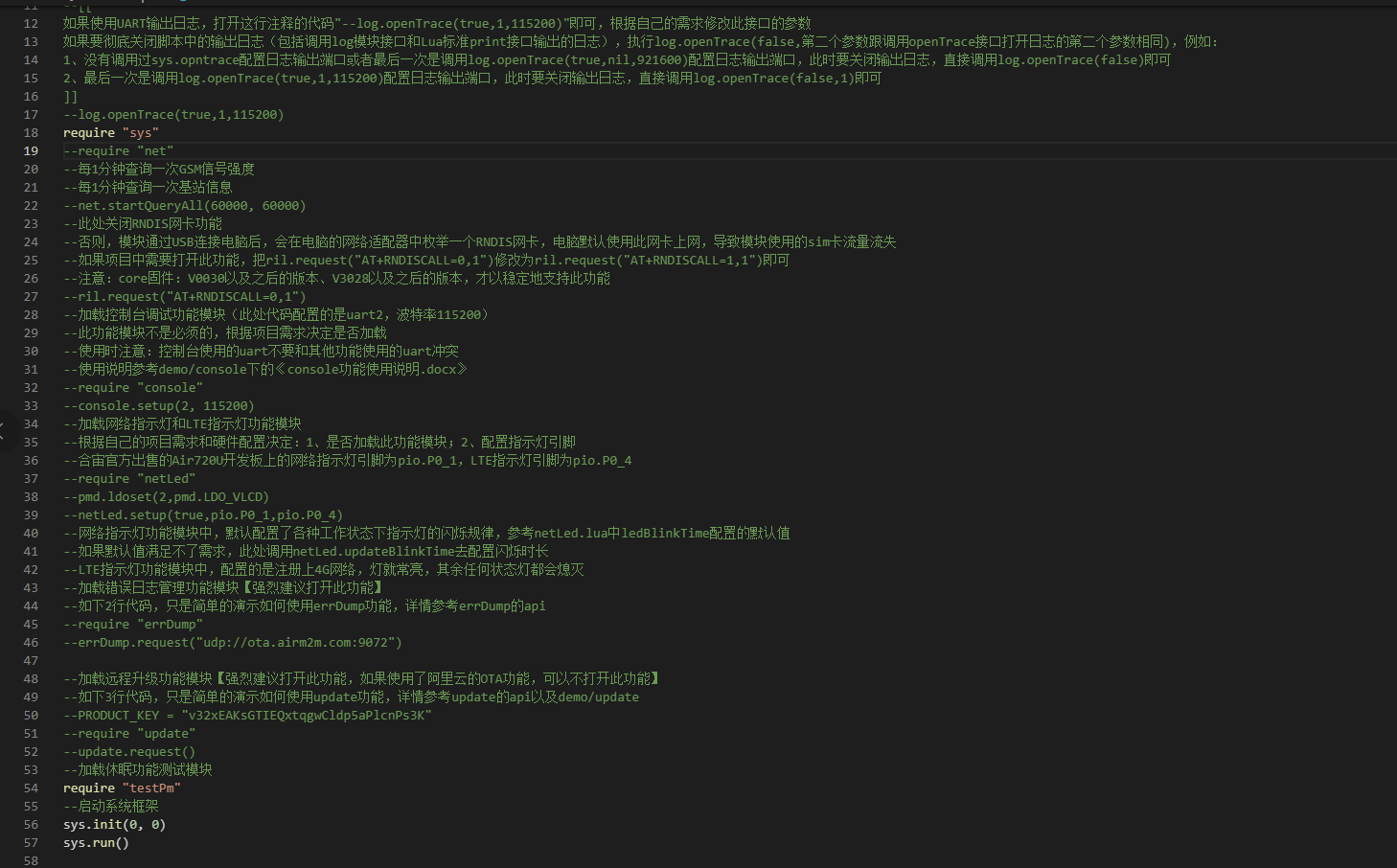
Comment out the rest of the code
-
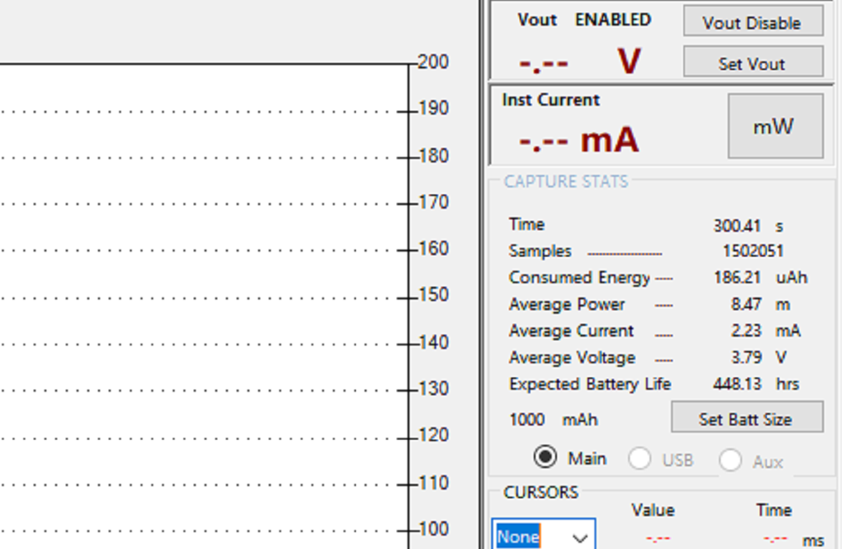
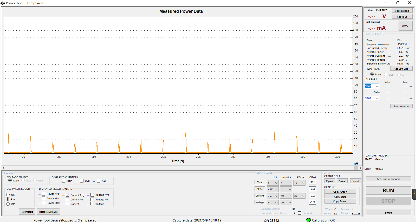
Power consumption during module sleep
After the burning script module starts, wait for a period of time (the time is uncertain), and the module will automatically enter sleep
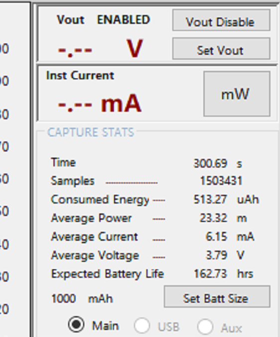
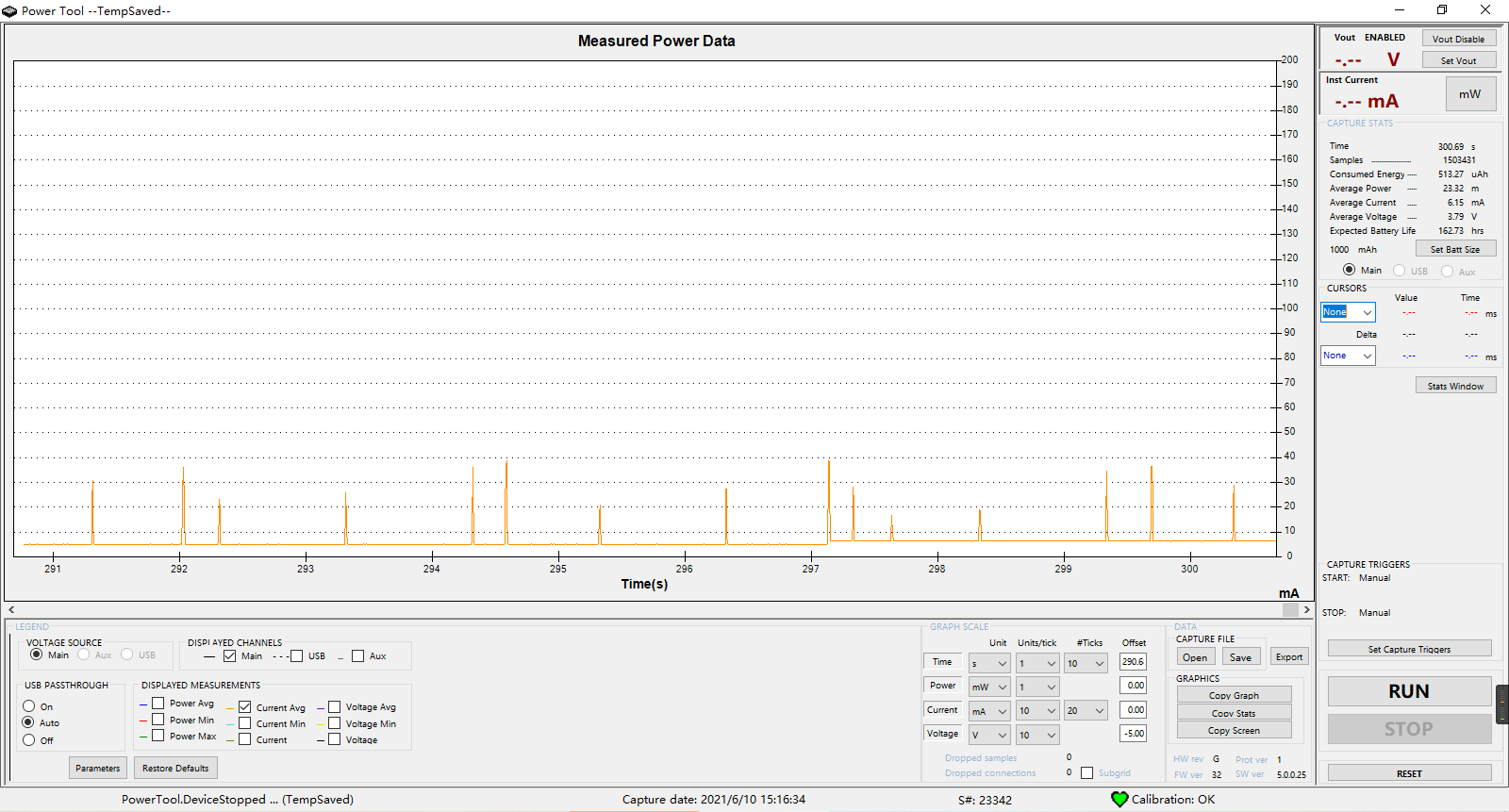
As can be seen in the figure, the average power consumption within five minutes after sleep is 2.23mA
-
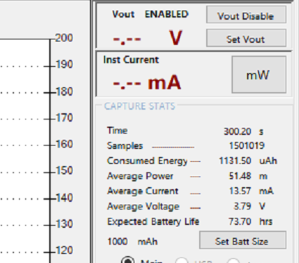
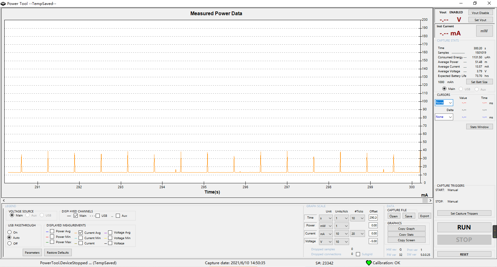
Power consumption of the module in the wake-up state
At testpm Add PM to the last line in Lua Wake (tag) can keep the module awake
pm.wake("TEST")
The average power consumption in 5 minutes is 13.57mA
Second example
This example is used to demonstrate the impact of sleep and wake-up on module functions and PM Wake (tag) and PM Application of sleep (tag)
Here is the script used in the second example. Please click me to download it
The overall function of this demo is: when the GPIO of the module_ 9 wake up the module when high-level interrupt is detected, and sleep the module when low-level interrupt is detected. Serial port is a channel commonly used to communicate with peripherals. It is a function that will be affected by sleep. Use the serial port debugging tool to send a string containing fixed characters to the serial port 2 of the module to control the three led lights on the development board and observe the state of the led lights when the module sleeps and wakes up
Because this demo is only to demonstrate the impact of sleep and wake-up on module functions, the development board for removing peripheral power consumers used in the first example is not used. Test with normal development board
Let's first talk about the phenomena we can observe through this example: when the module keeps waking up, the led lamp cycles on and off regularly; When the module is dormant, the led light turns on and off irregularly
Preparation before test
-
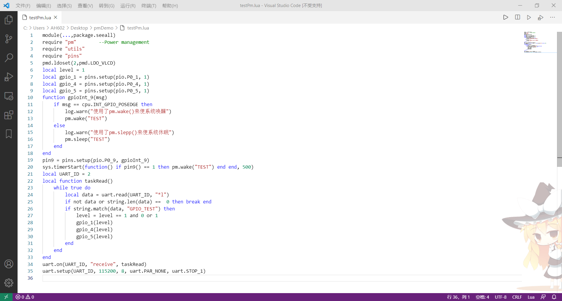
Set GPIO
GPIO_9 set to interrupt, GPIO_1,GPIO_4. GPIO5 initialization. These three gpios correspond to the green light, blue light and red light on the development board respectively
pmd.ldoset(2,pmd.LDO_VLCD) --open VLCD Voltage domain, give GPIO_1 And GPIO_4 power supply local level = 1 local gpio_1 = pins.setup(pio.P0_1, 1) local gpio_4 = pins.setup(pio.P0_4, 1) local gpio_5 = pins.setup(pio.P0_5, 1) function gpioInt_9(msg) --GPIO_9 Interrupt handling function if msg == cpu.INT_GPIO_POSEDGE then --Wake up when high level interrupt log.warn("Used pm.wake()Wake up the system") pm.wake("TEST") else --Sleep on low level interrupt log.warn("Used pm.slepp()Hibernate the system") pm.sleep("TEST") end end pin9 = pins.setup(pio.P0_9, gpioInt_9) --take GPIO_9 Set to interrupt sys.timerStart( --Because it is an interrupt, it should be detected once when starting up GPIO_9 If it is high, keep waking up function() --If it is low, it will not be processed, because the bottom layer will automatically enter sleep after the module is connected to the network if pin9() == 1 then pm.wake("TEST") end end , 500) -
Set serial port
Use serial port 2 to read the task. When the corresponding string is matched, control the state of LED light
local UART_ID = 2          										--Serial port 2
local function read()   										--Read function when serial port receives data
    while true do
        local data = uart.read(UART_ID, "*l")
        if not data or string.len(data) ==  0 then break end
        if string.match(data, "GPIO_TEST") then   --If there is a match in the data"GPIO_TEST"character string
            level = level == 1 and 0 or 1		     --Then control three led Light on and off
            gpio_1(level)
            gpio_4(level)
            gpio_5(level)
        end
    end
end

uart.on(UART_ID, "receive", read)								--Execute when the serial port receives data read
uart.setup(UART_ID, 115200, 8, uart.PAR_NONE, uart.STOP_1)		--Open serial port
Start test
Use Luatools to burn the script, check "serial port 1 print trace", after burning the script, unplug the USB from the development board (the module will not sleep when USB is connected), use DC power supply, connect it to UART2 of the module, and connect the serial port cable to UART1, as shown in the figure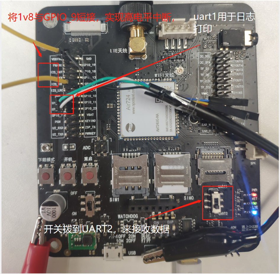
-
GPIO_9 is short circuited with 1V8 to generate high-level interrupt and call PM Wake (tag) to wake up the module
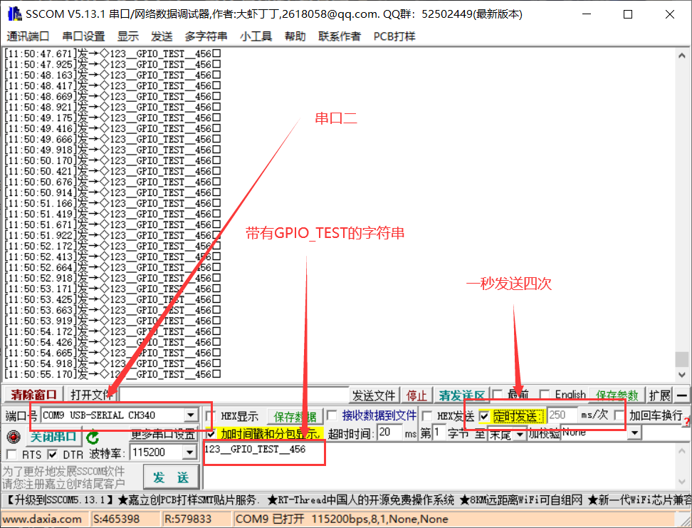
- Using the serial port debugging tool to send the data with "GPIO_TEST" to UART2, we can observe that the led light is on and off regularly, and we can observe the instantaneous current displayed by the DC power supply at the moment
-
Sending data four times per second, you can see that the led light on the development board is on and off twice a second
-
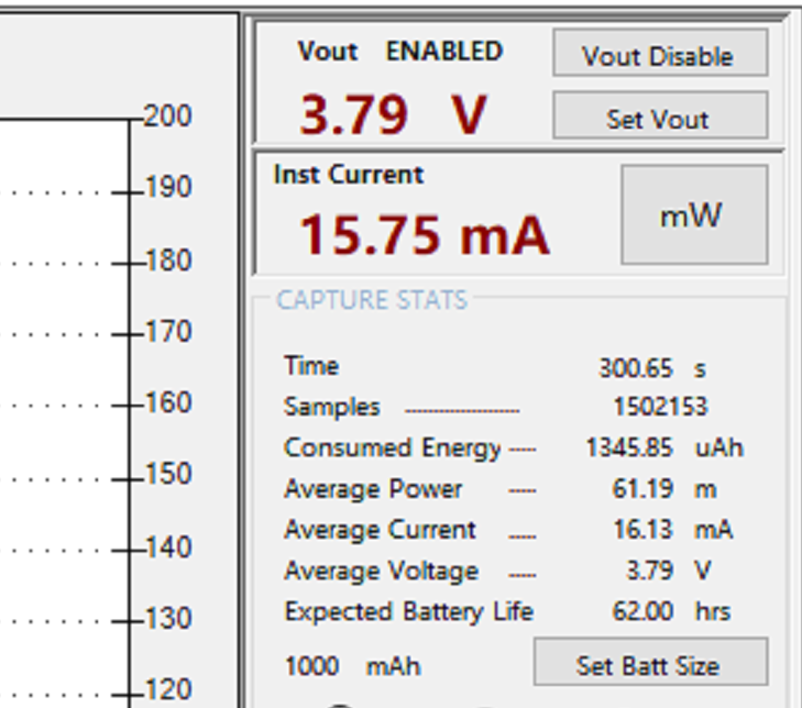
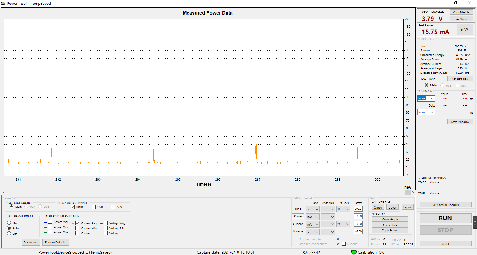
Maintain this wake-up state and observe the average current for 5 minutes
-
Connect 1v8 to GPIO_9 disconnect, generate low level interrupt, call PM Sleep ("TEST") makes the module sleep, and the serial port debugging assistant maintains the frequency of sending data four times in one second
- Observing the led light on the development board, we can see that the light will be on and off irregularly. The reason for this is that the serial port cannot receive or is difficult to receive data due to module sleep
-
Keep this sleep state again and observe the average current for 5 minutes. It will be found that the current is very low compared with that when waking up
When we need to use serial port to transmit data, we call pm. in advance. Wake (tag) wakes up the module to ensure that the serial port can send and receive data normally; After data transmission, in order to save power, call PM Sleep (tag) to sleep the module -
In use, we can use PM isSleep(tag)/pm. Issleep() to query the sleep status of a script or tag
sys.taskInit( function() while true do print("\"TEST\"Sleep state of:",pm.isSleep("TEST"),"Global sleep state:",pm.isSleep())) sys.wait(1000) end end )-
GPIO_ After 9 and 1v8 are short circuited, PM is called in the script wake(“TEST”)
The log will be printed circularly: sleep status of "TEST": false global sleep status: false
-
GPIO_ After 9 is disconnected from 1v8, PM is called in the script sleep(“TEST”)
The log will be printed circularly: sleep status of "TEST": true global sleep status: true
-
-
If there is more than one PM Wake (tag), what is the sleep state of the module
-
For example, there are several PM wake(tag)
pm.wake("TEST_1") pm.wake("TEST_2") pm.wake("TEST_3") pm.wake("TEST_4")At this time, use the following code to query the sleep status of the script, and the following return values will be obtained
print(pm.isSleep("TEST_1"))			--false
print(pm.isSleep("TEST_2")) 		--false
print(pm.isSleep("TEST_3")) 		--false
print(pm.isSleep("TEST_4"))			--false
print(pm.isSleep())					--false
The module remains awake without hibernation. Now use PM Sleep ("TEST_4") and PM Sleep ("TEST_2") to mark test_ 4 and test_ 2. After the work is completed, you can sleep, and then query the sleep status of tag and script again
pm.wake("TEST_1") pm.wake("TEST_2") pm.wake("TEST_3") pm.wake("TEST_4")

pm.sleep("TEST_2")
pm.sleep("TEST_4")

print(pm.isSleep("TEST_1")) 		--false
print(pm.isSleep("TEST_2")) 		--true
print(pm.isSleep("TEST_3")) 		--false
print(pm.isSleep("TEST_4"))			--true
print(pm.isSleep())					--false
Through the above return value, we will find that TEST_2 and TEST_4 is already dormant, but TEST_1 and TEST_3 is not in sleep state, so the script does not sleep globally. At this time, if you want to sleep the module, you need to use PM Sleep () makes all tag s sleep, and then the module will really go into sleep
pm.wake("TEST_1") pm.wake("TEST_2") pm.wake("TEST_3") pm.wake("TEST_4")

print(pm.isSleep("TEST_1")) 		--false
print(pm.isSleep("TEST_2"))			--false
print(pm.isSleep("TEST_3"))			--false
print(pm.isSleep("TEST_4"))			--false
print(pm.isSleep())					--false

pm.sleep("TEST_1")
pm.sleep("TEST_2")
pm.sleep("TEST_3")
pm.sleep("TEST_4")

print(pm.isSleep("TEST_1"))			--true
print(pm.isSleep("TEST_2"))			--true
print(pm.isSleep("TEST_3"))			--true
print(pm.isSleep("TEST_4"))			--true
print(pm.isSleep())					--true
-
common problem
Why can't the module sleep
1. Check whether the module is inserted USB,USB When connected, the module remains awake and cannot sleep
2. Use the development board and your own board to burn adc of demo Compare to see if the module can sleep
3. use pm.isSleep()The interface queries the sleep state of the script to see if it is called pm.wake(tag)No call after pm.sleep(tag)
4. Mask the code to see which part of the code makes the module unable to sleep
Why can serial port 1 send and receive data normally in the sleep state
uart1 stay core Special processing is made in the, which can realize that the received data is not lost in the sleep state