NEC protocol infrared remote controller
The communication distance of home appliance remote controller is often not high, and the cost of infrared is much lower than other wireless devices, so infrared always occupies a place in the application of home appliance remote controller. There are many baseband communication protocols for the remote controller, about dozens of which are commonly used, such as ITT protocol, NEC protocol, Sharp protocol, Philips RC-5 protocol, Sony SIRC protocol, etc. NEC protocol is used most. Therefore, the remote controller matched with KST-51 development board directly adopts NEC protocol. We will explain it with NEC protocol standard in this lesson.
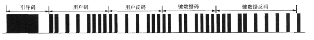
The data format of NEC protocol includes boot code, user code User code (or user code inversion), key key code and key code inversion, and the last stop bit. The stop bit is mainly used for isolation, which is generally not judged and ignored during programming. The data code consists of 4 bytes and 32 bits, as shown in the figure below. The first byte is the user code, and the second byte may also be the user code, or the inverse code of the user code, which is generated by The manufacturer decides that the third byte is the key data code of the current key, and the fourth byte is the inverse code of the key data code, which can be used to correct the data.
This NEC protocol does not represent data as intuitively as we have learned before, such as UART, but each bit of data itself needs to be encoded and then carrier modulated.
- Pilot code: 9 ms carrier + 4.5 ms idle.
- Bit value "0": 560 us carrier + 560 us idle.
- Bit value "1": 560 us carrier + 1.68 ms idle.
Combined with the above figure, we can see that the first dark section is the 9 ms carrier of the pilot code, followed by the 4.5 ms idle of the pilot code, while the data code behind is the intersection of many carriers and idle, and their length is determined by the specific data to be transmitted. HS0038B, an infrared integrated receiver, will output a low level when it receives a carrier signal and a high level when it is idle. We use the logic analyzer to grab an infrared key and understand it through the graphics decoded by HS0038B, as shown in the following figure.
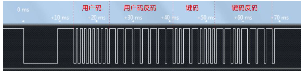
As can be seen from the figure, the first byte of the data code is 9 ms carrier plus 4.5 ms idle start code, the low bit is first, and the high bit is last. The first byte of the data code is 8 groups of 560 us carriers plus 560 us idle, that is 0x00, and the second byte is 8 groups of 560 us carriers plus 1.68 ms idle, which can be seen as 0xFF. These two bytes are the inverse code of user code and user code. The binary key code of the key is 0x0C, the inverse code is 0xF3, and finally followed by a 560 us carrier stop bit. For our remote control, different keys are the difference between key code and key code inverse code. The user code is the same. In this way, we can analyze the key code of the current key through the program of single chip microcomputer.
When we learned the interrupt, we learned that 51 MCU has two external interrupts: external interrupt 0 and external interrupt 1. Our infrared receiving pin is connected to P3 On pin 3, the second function of this pin is external interrupt 1. bit3 and bit2 in the register TCON are two bits related to external interrupt 1. IE1 is the external interrupt flag bit. When an external interrupt occurs, this bit is automatically set to 1, which is similar to the timer interrupt flag bit TF. It will be cleared automatically after entering the interrupt, or it can be cleared by software. Bit2 sets the external interrupt type. If bit2 is 0, P3 If bit2 is 1, P3 3 the interrupt can be triggered only when the falling edge from high level to low level occurs. In addition, the external interrupt 1 enable bit is EX1. Then let's write the program and use the nixie tube to display the user code and key code of the remote control.
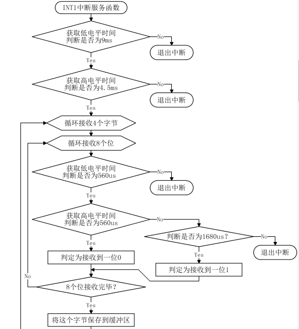
Infrared.c file is mainly used to detect infrared communication. When an external interrupt occurs, enter the external interrupt. When timer 1 is timed, first judge the guide code, and then obtain the time of high and low levels for each bit of the data code bit by bit, so as to know whether each bit is 0 or 1, and finally solve the data code. Although the final function is very simple, because of the complexity of the coding itself, the interrupt program of infrared reception is logically more complex. First, we provide the program flow chart of the interrupt function. You can understand the program code by referring to the flow chart
/***************************Infrared.c File program source code*****************************/
#include <reg52.h>
sbit IR_INPUT = P3^3; //Infrared receiving pin
bit irflag = 0; //Infrared receiving flag, set 1 after receiving a frame of correct data
unsigned char ircode[4]; //Infrared code receiving buffer

/* Initialize infrared receiving function */
void InitInfrared(){
    IR_INPUT = 1; //Ensure that the infrared receiving pin is released
    TMOD &= 0x0F; //Clear the control bit of T1
    TMOD |= 0x10; //Configure T1 to mode 1
    TR1 = 0; //Stop T1 count
    ET1 = 0; //Disable T1 interrupt
    IT1 = 1; //Set INT1 as negative edge trigger
    EX1 = 1; //Enable INT1 interrupt
}
/* Gets the duration of the current high level */
unsigned int GetHighTime(){
    TH1 = 0; //Reset T1 count initial value
    TL1 = 0;
    TR1 = 1; //Start T1 count
    while (IR_INPUT){ //When the infrared input pin is 1, the cycle detection waits, and when it changes to 0, the cycle ends
        //When the T1 count value is greater than 0x4000, that is, the high-level duration exceeds about 18ms,
        //Forced exit from the loop is to avoid the program pretending to die here when the signal is abnormal.
        if (TH1 >= 0x40){
            break;
        }
    }
    TR1 = 0; //Stop T1 count
    return (TH1*256 + TL1); //The T1 count value is synthesized into a 16bit integer number and returned
}
/* Gets the duration of the current low level */
unsigned int GetLowTime(){
    TH1 = 0; //Reset T1 count initial value
    TL1 = 0;
    TR1 = 1; //Start T1 count
    while (!IR_INPUT){ //When the infrared input pin is 0, the cycle detection waits, and when it changes to 1, the cycle ends
        //When the T1 count value is greater than 0x4000, that is, the low-level duration exceeds about 18ms,
        //Forced exit from the loop is to avoid the program pretending to die here when the signal is abnormal.
        if (TH1 >= 0x40){
            break;
        }
    }
    TR1 = 0; //Stop T1 count
    return (TH1*256 + TL1); //The T1 count value is synthesized into a 16bit integer number and returned
}
/* INT1 Interrupt service function to perform infrared reception and decoding */
void EXINT1_ISR() interrupt 2{
    unsigned char i, j;
    unsigned char byt;
    unsigned int time;

    //Receive and determine the 9ms low level of the pilot code
    time = GetLowTime();
    //The time determination range is 8.5 ~ 9.5ms,
    //If it exceeds this range, it means error code and exit directly
    if ((time<7833) || (time>8755)){
        IE1 = 0; //Clear INT1 interrupt flag before exiting
        return;
    }
    //Receive and determine the 4.5ms high level of the pilot code
    time = GetHighTime();
    //The time determination range is 4.0 ~ 5.0ms,
    //If it exceeds this range, it means error code and exit directly
    if ((time<3686) || (time>4608)){
        IE1 = 0;
        return;
    }
    //Receive and determine the subsequent 4-byte data
    for (i=0; i<4; i++){ //Cycle to receive 4 bytes
        for (j=0; j<8; j++){ //Cyclic reception determines 8 bit s per byte
            //Receive and determine 560us low level per bit
            time = GetLowTime();
            //The time determination range is 340 ~ 780us,
            //If it exceeds this range, it means error code and exit directly
            if ((time<313) || (time>718)){
                IE1 = 0;
                return;
            }
            //Receive the high-level time of each bit and determine the value of the bit
            time = GetHighTime();
            //The time determination range is 340 ~ 780us,
            //Within this range, the bit value is 0
            if ((time>313) && (time<718)){
                byt >>= 1; //Because the low order comes first, the data moves to the right and the high order is 0
                //The time determination range is 1460 ~ 1900us,
                //Within this range, the bit value is 1
            }else if ((time>1345) && (time<1751)){
                byt >>= 1; //Because the low order comes first, the data moves to the right,
                byt |= 0x80; //High position 1
            }else{ //If it is not within the above range, it will be described as bit error and exit directly
                IE1 = 0;
                return;
            }
        }
        ircode[i] = byt; //After receiving a byte, it is saved to the buffer
    }
    irflag = 1; //Set the flag after receiving
    IE1 = 0; //Clear INT1 interrupt flag before exiting
}
When you read this program, you will find that the senior made a timeout judgment if (Th1 > = 0x40) when obtaining the high and low level time, This timeout judgment is mainly to deal with the abnormal input signal (such as accidental interference). If the timeout judgment is not made, when the input signal is abnormal, the program may wait for an unreachable jump edge, causing the program to fake death.
In addition, the signal sent by pressing the key on the remote control is different from that by pressing and holding the key continuously. Let's compare the measured signal waveforms of the two key modes
Infrared single key sequence diagram
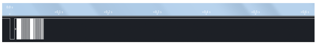
Infrared continuous key sequence diagram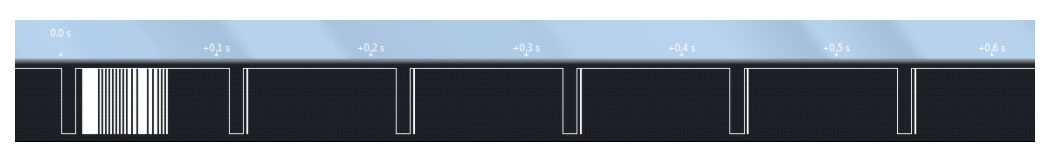
The result of a single key press 16-9 is the same as our previous figure 16-8, which does not need to be explained. When you press the key continuously, you will first send out the same waveform as a single key. After about 40 ms, a 9 ms carrier plus 2.25 ms idle and then a stop bit waveform will be generated. This is called a repeat code. Then, as long as you still press and hold the key, a repeat code will be generated every 108 ms. For this duplicate code, our program does not analyze it separately, but directly ignores it, which does not affect the reception of normal key data. If you need to use this duplicate code when making programs in the future, you only need to add the analysis of the duplicate code.