Simple filter
In our usual image processing process, the longest thing to do is to change the overall image of a certain color.
Let's take an example. If we change the R value of all RGB to 0.5 times the original value, according to the previous wiki, the process of drawing a graph is vertex and fragment, and fragment is responsible for drawing the color of each pixel.
fragment float4 myFragmentShader(
                                VertexOut vertexIn [[stage_in]],
                            texture2d<float,access::sample>   inputImage   [[ texture(0) ]],
                                 sampler textureSampler [[sampler(0)]]
                             )
{
    float4 color = inputImage.sample(textureSampler, vertexIn.texCoords);
    return color;

}
So in this shader, multiplying the r value of the color returned by 0.5 can achieve the desired effect.
return float4(color.r * 0.5 ,color.gba)
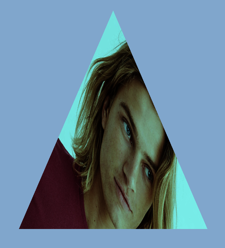
Re-running our previous demo, our triangle is a little green, indicating that our effect has been achieved.
ColorLUT
But the above is the ideal situation, the processing of general pictures will be much more complex.
Suppose our picture is 1280 * 720 pixels, then 921600 floating point operations are performed, multiplying the r value of each pixel by 0.5.
If the picture is small, there is no pressure on GPU computing, but when the picture is larger and the number is more, it will affect the speed of GPU computing.
look up table
As the name implies, it is a look-up table, while ColorLUT is a color look-up table.
So a query table is introduced to store the corresponding transformed pixels. When used, only one query operation is needed. This operation will be much faster than the previous query table operation, especially in the case of load color operation.
But to store all the color changes, assume RGB24, one is 8*324 bits, RGB each color is 0-255, all 16777216 color changes, save all 256*256*256*24/8/1024/1024=48 mb, if each filter is 48 mb, so many filters in the image processing software, the size of app must not be endless. ?
So in order to solve this problem, there are standard filter pictures such as ColorLut. By default, the following pictures, 512*512, represent all color changes. If the color in the picture is not the corresponding difference:
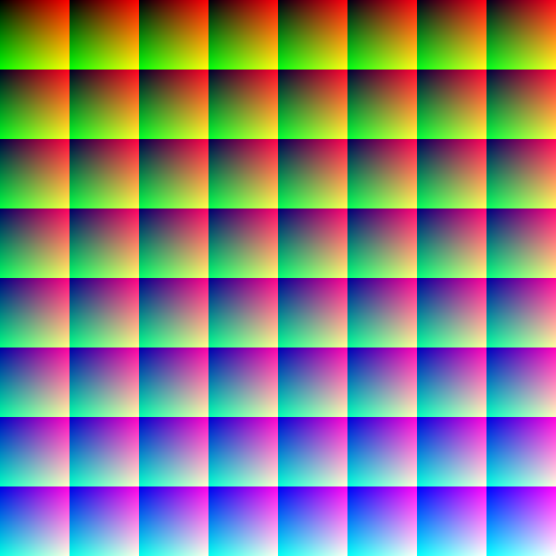
This is a standard color image, rbg is the original color, so adjust the color of this image, and then get a new lut image, the new image plus the modified lut image filter can query the corresponding color how to replace, and then to the new image.
Let's explain the above picture and how to use it.
First look at the picture.
- 8*8 Square Composition
- Overall, the top left corner of each square changes from black to blue from top left to bottom right.
- The upper right corner of each individual square is mainly red.
- The lower left corner of each square is mainly green.
Does the above information give you any inspiration?
We're simplifying a little.
The color is three values of r g b, which are expressed as normalized values (1 for 255).
- As a whole, for each small box, from top left to bottom right b from 0 to 1 is the order of z fonts.
- For each small box alone, r from left to right is from 0 to 1, representing x.
- For each small box alone, from top to bottom g is from 0 to 1, representing y.
So the position corresponding to the pure blue of 0, 0, 1 is (7 * 64, 7 * 64), the square in the lower right corner.
Now let's illustrate the query process through an example.
Suppose that the colors we need to obtain now are (0.4, 0.6, 0.2) using normalized coordinates.
- First, we determine which square b = 0.2 * 63 = 12.6, that is (4, 1) which one to use.
- r = 0.4 * 63 = 25.6, g = 0.6 * 63 = 37.8 to convert to macrocoordinates (4 * 64 + 25.6, 1 * 64 + 37.8)
- The first three steps are all floating-point numbers, but the pixels of our filters are fixed and there are no decimal numbers.
- For r,g finally converts the arrival coordinates to normalized coordinates, ((4*64+25.6)/512, (1*64+37.8)/512), and extracts the exact color values by sampler interpolation.
- For b, we can take the next box (5,1) and mix the two colors to get the final color.
Metal Image Processing
In the last article, we mentioned that CommandBuffer has three Encoder s.
- MTL RenderCommand Encoder Rendering 3D Encoder
- MTLComputeCommand Encoder Computing Encoder
- MTLBlitCommand Encoder Bitmap Copy Encoder Copy buffer texture can also generate mipmap
Previous demo is a simple image rendering, using the Encoder of MTL RenderCommand Encoder.
This time we add filters to the picture, using MTLComputeCommandEncoder, through the computing power of GPU, to query lut for us, and mix color operations.
In short, compared with the previous rendering operation, the texture of the input image can be rendered. What we need to do is to have a processing method for the filter. We input the texture of the original image texture and lut image to the GPU, and the GPU returns to us a new texture of the image with the filter added. We give the texture to our previous rendering Encoder. It will draw a picture in the triangle after we add filters.
We continue the previous demo, Device and CommandQueue, CommandBuff, and by default we have added a Compute Encoder before the previous rendering Encoder.
-
Each Encoder needs a PipelineState responsible for linking Shader's methods
A new ComputePipeline State is created here, and the corresponding shader method will be introduced later.id<MTLLibrary> library = [device newDefaultLibrary]; id<MTLFunction> function = [library newFunctionWithName:@"image_filiter"]; self.computeState = [device newComputePipelineStateWithFunction:function error:nil]; -
Configure resources, original images and lut images.
The following is a method of converting UI Image to Texture, drawn through CGContext.
    - (void)setLutImage:(UIImage *)lutImage{
    _lutImage = lutImage;

    CGImageRef imageRef = [_lutImage CGImage];

    // Create a suitable bitmap context for extracting the bits of the image
    NSUInteger width = CGImageGetWidth(imageRef);
    NSUInteger height = CGImageGetHeight(imageRef);
    CGColorSpaceRef colorSpace = CGColorSpaceCreateDeviceRGB();
    uint8_t *rawData = (uint8_t *)calloc(height * width * 4, sizeof(uint8_t));
    NSUInteger bytesPerPixel = 4;
    NSUInteger bytesPerRow = bytesPerPixel * width;
    NSUInteger bitsPerComponent = 8;
    CGContextRef bitmapContext = CGBitmapContextCreate(rawData, width, height,
                                                       bitsPerComponent, bytesPerRow, colorSpace,
                                                       kCGImageAlphaPremultipliedLast | kCGBitmapByteOrder32Big);
    CGColorSpaceRelease(colorSpace);


    CGContextDrawImage(bitmapContext, CGRectMake(0, 0, width, height), imageRef);
    CGContextRelease(bitmapContext);

    MTLRegion region = MTLRegionMake2D(0, 0, width, height);
    [self.lutTexture replaceRegion:region mipmapLevel:0 withBytes:rawData bytesPerRow:bytesPerRow];

    free(rawData);
    }
- Configure configurable parameters, such as mixing of filters, return, etc.
Here I created a new struct, which represents the return and strength of the added filter. By bytes, the corresponding configuration can be transferred to the shader.
typedef struct
{

    UInt32 clipOriginX;
    UInt32 clipOriginY;
    UInt32 clipSizeX;
    UInt32 clipSizeY;
    Float32 saturation;
    bool changeColor;
    bool changeCoord;

    }ImageSaturationParameters;
-
Configure Encoder
Assemble all the above components. SorceTexture is the input picture texture, destination Texture is the picture texture to be written.
self.lutTexture is the input filter picture texture, which is divided into 0, 1, 2 input sources corresponding to texture.
The parameter configuration is passed into the shader as bytes.
ImageSaturationParameters params; params.clipOriginX = floor(self.filiterRect.origin.x); params.clipOriginY = floor(self.filiterRect.origin.y); params.clipSizeX = floor(self.filiterRect.size.width); params.clipSizeY = floor(self.filiterRect.size.height); params.saturation = self.saturation; params.changeColor = self.needColorTrans; params.changeCoord = self.needCoordTrans; id<MTLComputeCommandEncoder> encoder = [commandBuffer computeCommandEncoder]; [encoder pushDebugGroup:@"filter"]; [encoder setLabel:@"filiter encoder"]; [encoder setComputePipelineState:self.computeState]; [encoder setTexture:sourceTexture atIndex:0]; [encoder setTexture:destinationTexture atIndex:1]; if (self.lutTexture == nil) { NSLog(@"lut == nil"); [encoder setTexture:sourceTexture atIndex:2]; }else{ [encoder setTexture:self.lutTexture atIndex:2]; } [encoder setSamplerState:self.samplerState atIndex:0]; [encoder setBytes:¶ms length:sizeof(params) atIndex:0]; ``` 5. threadgroups //In Compute encoder, in order to improve the efficiency of computing, every picture is divided into a small unit and sent to GPU for parallel processing. The number of groups and the size of each group are configured by Encder.  //In order to maximize the efficiency of GPU computing, it can be configured as follows:
NSUInteger wid = self.computeState.threadExecutionWidth;
NSUInteger hei = self.computeState.maxTotalThreadsPerThreadgroup / wid;

MTLSize threadsPerGrid = {(sourceTexture.width + wid - 1) / wid,(sourceTexture.height + hei - 1) / hei,1};
MTLSize threadsPerGroup = {wid, hei, 1};


[encoder dispatchThreadgroups:threadsPerGrid
threadsPerThreadgroup:threadsPerGroup];

```
- Shader
This is the core computing logic. Unlike previous rendering, it is neither vertex nor fragment, but modified by a new kernel. Specifically, it is the code version of the interpreted lut above. If you can understand the location of the lut coordinates above, there is no problem with the relevant code below.
At the same time, the following code also adds a judgment on whether the scope of the filter needs to be added. It can be seen that the sampler can be reused, and different texture s can use the same sampler.
You can see that the image_file ITER function has six input values, which are configuration parameters, original texture, written target texture, filter texture, sampler, and execution position (the parameter returns the position calculated in the previously configured threadgroup, which is located in the whole image, not the normalized value, and the corresponding can be obtained by direct sampling. Location color)
//check the point in pos
bool checkPointInRect(uint2 point,uint2 origin, uint2 rect){
    return point.x >= origin.x &&
    point.y >= origin.y &&
    point.x <= (origin.x + rect.x) &&
    point.y <= (origin.y + rect.y);
}
kernel void image_filiter(constant ImageSaturationParams *params [[buffer(0)]],
                          texture2d<half, access::sample> sourceTexture [[texture(0)]],
                          texture2d<half, access::write> targetTexture [[texture(1)]],
                          texture2d<half, access::sample> lutTexture [[texture(2)]],
                          sampler samp [[sampler(0)]],
                          uint2 gridPos [[thread_position_in_grid]]){


    float2 sourceCoord = float2(gridPos);
    half4 color = sourceTexture.sample(samp,sourceCoord);


    float blueColor = color.b * 63.0;

    int2 quad1;
    quad1.y = floor(floor(blueColor) / 8.0);
    quad1.x = floor(blueColor) - (quad1.y * 8.0);

    int2 quad2;

    quad2.y = floor(ceil(blueColor) / 8.0);
    quad2.x = ceil(blueColor) - (quad2.y * 8.0);

    half2 texPos1;
    texPos1.x = (quad1.x * 0.125) + 0.5/512.0 + ((0.125 - 1.0/512.0) * color.r);
    texPos1.y = (quad1.y * 0.125) + 0.5/512.0 + ((0.125 - 1.0/512.0) * color.g);

    half2 texPos2;
    texPos2.x = (quad2.x * 0.125) + 0.5/512.0 + ((0.125 - 1.0/512.0) * color.r);
    texPos2.y = (quad2.y * 0.125) + 0.5/512.0 + ((0.125 - 1.0/512.0) * color.g);


    half4 newColor1 = lutTexture.sample(samp,float2(texPos1.x * 512 ,texPos2.y * 512));
    half4 newColor2 = lutTexture.sample(samp,float2(texPos2.x * 512,texPos2.y * 512 ));

    half4 newColor = mix(newColor1, newColor2, half(fract(blueColor)));


    half4 finalColor = mix(color, half4(newColor.rgb, color.w), half(params->saturation));


    uint2 destCoords = gridPos + params->clipOrigin;


    uint2 transformCoords = destCoords;

    //transform coords for y
    if (params->changeCoord){
        transformCoords = uint2(destCoords.x, sourceTexture.get_height() - destCoords.y);
    }
    //transform color for r&b
    half4 realColor = finalColor;
    if (params->changeColor){
        realColor = half4(finalColor.bgra);
    }

    if(checkPointInRect(transformCoords,params->clipOrigin,params->clipSize))
    {
        targetTexture.write(realColor, transformCoords);

    }else{

        targetTexture.write(color,transformCoords);
    }
}
7. calculation
After all the above steps have been configured, you can encode.
[encoder endEncoding];
After performing the above steps, we get a destination texture after adding the filter, pass the text to the previous rendering process, and we can get a triangle with the effect of the filter!
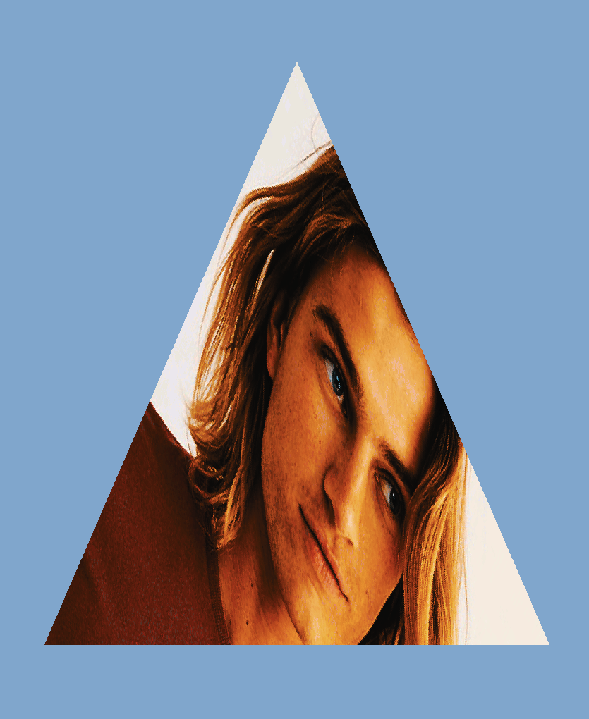
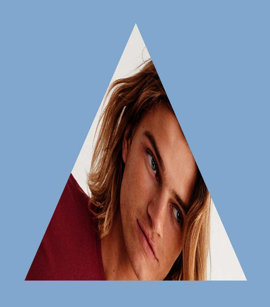
Contrast the original picture below
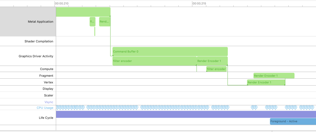
From the Metal System Trace, it is obvious from the label that there is an additional Compute encoder before our render.
summary
Above is the image processing work implemented by ComputeEncoder. In fact, some complex mathematical calculations can be transferred to GPU by ComputeEncoder, such as a large number of matrix operations required by machine learning.
The overall process is the same as previous enders. The only difference may be the configuration of threadgroup.
Reference resources:
wiki - Colour_look-up_table
Metal Programming Guide
Fast fabrication of filters using CIColorCube