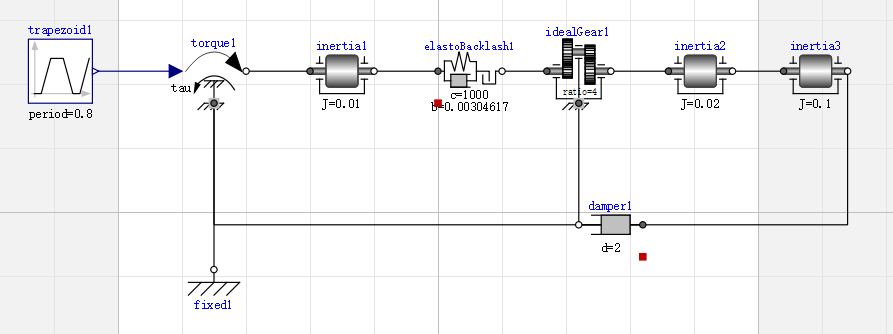
Suppose we want to establish a model of gear assembly, the schematic diagram is as follows:

Method 1: component-based modeling
Component-based modeling is to directly drag and connect components and set corresponding parameter values.

After the model is established, switch to the code view (automatically generate code) as follows:
model Gear_assembly
  extends Modelica.Icons.Example;
  Modelica.Blocks.Sources.Trapezoid trapezoid1(period = 0.8) annotation(
    Placement(visible = true, transformation(origin = {-118, 44}, extent = {{-10, -10}, {10, 10}}, rotation = 0)));
  Modelica.Mechanics.Rotational.Sources.Torque torque1 annotation(
    Placement(visible = true, transformation(origin = {-70, 44}, extent = {{-10, -10}, {10, 10}}, rotation = 0)));
  Modelica.Mechanics.Rotational.Components.Inertia inertia1(J = 0.01) annotation(
    Placement(visible = true, transformation(origin = {-30, 44}, extent = {{-10, -10}, {10, 10}}, rotation = 0)));
  Modelica.Mechanics.Rotational.Components.ElastoBacklash elastoBacklash1(b = 0.00304617, c = 1000) annotation(
    Placement(visible = true, transformation(origin = {10, 44}, extent = {{-10, -10}, {10, 10}}, rotation = 0)));
  Modelica.Mechanics.Rotational.Components.IdealGear idealGear1(ratio = 4) annotation(
    Placement(visible = true, transformation(origin = {44, 44}, extent = {{-10, -10}, {10, 10}}, rotation = 0)));
  Modelica.Mechanics.Rotational.Components.Inertia inertia2(J = 0.02) annotation(
    Placement(visible = true, transformation(origin = {82, 44}, extent = {{-10, -10}, {10, 10}}, rotation = 0)));
  Modelica.Mechanics.Rotational.Components.Inertia inertia3(J = 0.1) annotation(
    Placement(visible = true, transformation(origin = {118, 44}, extent = {{-10, -10}, {10, 10}}, rotation = 0)));
  Modelica.Mechanics.Rotational.Components.Damper damper1(d = 2) annotation(
    Placement(visible = true, transformation(origin = {54, -4}, extent = {{10, -10}, {-10, 10}}, rotation = 0)));
  Modelica.Mechanics.Rotational.Components.Fixed fixed1 annotation(
    Placement(visible = true, transformation(origin = {-70, -18}, extent = {{-10, -10}, {10, 10}}, rotation = 0)));
equation
  connect(idealGear1.support, damper1.flange_b) annotation(
    Line(points = {{44, 34}, {44, -4}}));
  connect(damper1.flange_a, torque1.support) annotation(
    Line(points = {{64, -4}, {-70, -4}, {-70, 34}}));
  connect(damper1.flange_b, inertia3.flange_b) annotation(
    Line(points = {{44, -4}, {128, -4}, {128, 44}}));
  connect(torque1.tau, trapezoid1.y) annotation(
    Line(points = {{-82, 44}, {-106, 44}}, color = {0, 0, 127}));
  connect(torque1.flange, inertia1.flange_a) annotation(
    Line(points = {{-60, 44}, {-40, 44}}));
  connect(torque1.support, fixed1.flange) annotation(
    Line(points = {{-70, 34}, {-70, -18}}));
  connect(inertia1.flange_b, elastoBacklash1.flange_a) annotation(
    Line(points = {{-20, 44}, {0, 44}}));
  connect(elastoBacklash1.flange_b, idealGear1.flange_a) annotation(
    Line(points = {{20, 44}, {34, 44}}));
  connect(inertia3.flange_a, inertia2.flange_b) annotation(
    Line(points = {{108, 44}, {92, 44}}));
  connect(inertia2.flange_a, idealGear1.flange_b) annotation(
    Line(points = {{72, 44}, {54, 44}, {54, 44}, {54, 44}}));
end Gear_assembly;
Method 2: subsystem based modeling
Subsystem model is a model composed of components or other subsystems. In order to avoid redundancy, we can package the commonly used subsystems to facilitate the direct use of subsystems for modeling when building models in the future.
In the case of gear assembly, we can package the basket into an engine subsystem. The steps are as follows:
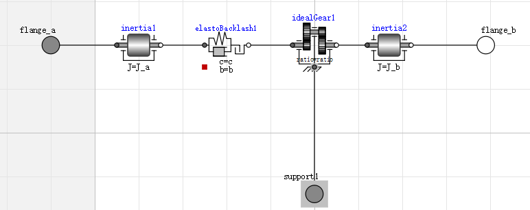
Step 1: use the component-based modeling method to do a good job in the components in the subsystem and the connection relationship between components.

Step 2: add the interface between subsystem and external communication to the model and connect it with internal components.

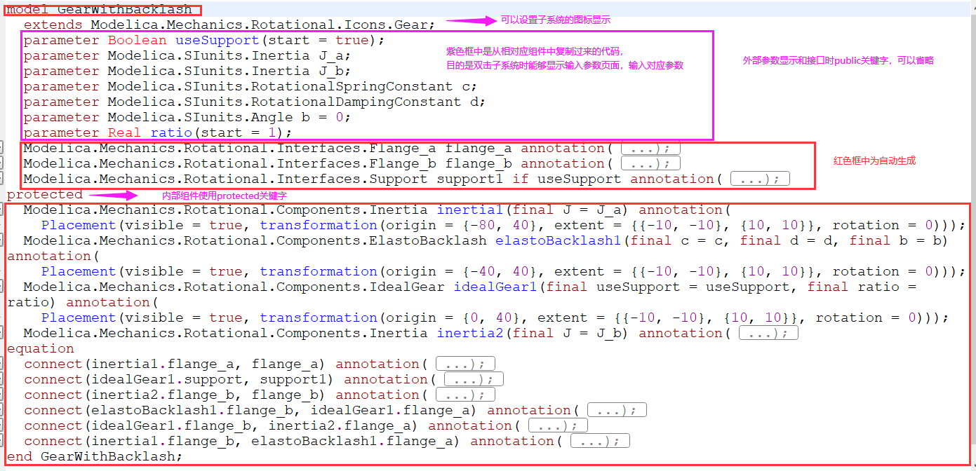
step3: switch to the code view and write the parameters you need to set the initial parameters in the front of the model (you can set the default value). The purpose of this is to double-click the model to directly display the input parameters page when you reuse the model later. Note that the code does not need to be handwritten. You can directly enter the code view of the corresponding component and copy the corresponding parameter line. Then set the keyword of the internal components of the subsystem to protected, and the keyword of the interface and input parameters communicating with the outside world to public (can be omitted). If you want to set the subsystem icon, you can inherit the engine icon. As shown in the figure:

The copying method of parameter code takes the parameters of inertial element as an example

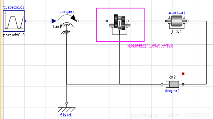
step4: finally, when we build the model of the gear assembly, we can drag the subsystem directly to the page to build it, as shown in the figure below.

Reference book: Modelica example tutorial (author: Dr.Michael M.Tiller, translator: Xie Dongping)