What is MPU6050?
It is a 6-axis motion processing chip composed of 3-axis gyroscope and 3-axis acceleration sensor. It can also connect magnetic sensor (such as GY-282 magnetic compass) through a reserved IIC interface. Other models include MPU6000, MPU9150, MPU9250, etc.
Fast hardware setup:
Communication interface: IIC
Power supply: 2.4-3.4V
Logic interface level: 1.8V
Typical circuit: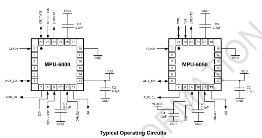
Pin description: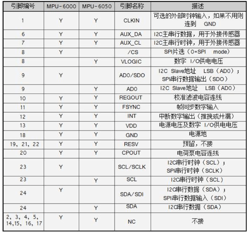
The 8th VLOGIC is generally connected to the power supply directly. (connecting different voltages refers to the IO port voltage. If the pin is connected to 1.8V, the IO port logic voltage is 1.8V.)
The 9th pin is IIC address selection, connected to low: address 0x68, connected to high: address 0x69;
Connection circuit with MCU (STM32 for example):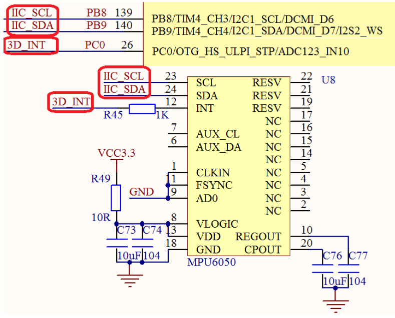
Characteristic parameters:
① Output rotation matrix, quaternion (, Euler Angle format (fusion algorithm data of Euler Angle) of 6-axis or 9-axis (external magnetic sensor is required) in digital form (DMP support is required)
② 3-axis angular velocity sensor gyroscope with 131 LSBs/ LSBs / ° ° / sec sensitivity and full cell sensing range of ± 250, ± 500, ± 1000 and ± 2000 ° / sec
 ③ Integrated programmable 3-axis acceleration sensor with range of ± 2g, ± 4g, ± 8g and ± 16g
 ④ Remove the sensitivity between the accelerator and the gyroscope axis, reduce the influence given by the setting and the drift of the sensor
 ⑤ DMP (digital motion engine) can reduce the load of MCU's complex fusion algorithm data, sensor synchronization, pose sensing, etc
 ⑥ The built-in operation time deviation and magnetic sensor correction algorithm technology eliminate the need of customers for additional correction
 ⑦ With a digital temperature sensor
 ⑧ With digital input synchronization pin (Sync supports video electronic phase stabilization technology and GPS
 ⑨ Programmable interrupt, which supports gesture recognition, panning, picture zooming, scrolling, fast descent interrupt, high G interrupt, zero motion sensing, touch sensing and shake sensing functions
 ⑩ VDD supply voltage is 2.5V 5%, 3.0V 5%, 3.3V 5%, VLOGIC can be as low as 1.8V 5%
⑪ Working current of gyroscope: 5mA, standby current of gyroscope: 5uA; working current of accelerator: 500uA, power saving mode current of accelerator: 40uA@10Hz
 ⑫ With 1024 byte FIFO, it helps to reduce system power consumption
 ⑬ IIC communication interface up to 400Khz
 ⑭ Ultra small package size: 4x4x0.9mm QFN
Rapid development of MPU6050 program:
Procedure development steps:
Initialization of MPU6050:
1. Initialize IIC interface;
2. Set the range of angular velocity sensor and acceleration sensor;
3. Set other parameters, such as:
      Configure interrupt, set AUX IIC interface, set FIFO, set gyro sampling rate, set digital filter, etc.
4. Set the system clock;
5. Enable angular velocity and acceleration sensor;
These settings are set by configuring the MPU6050 internal register. For details, please refer to the introduction of MPU6050 chapter on positive point atom;
The following is the MPU6050 initialization code of the punctual atom STM32:
u8 MPU_Init(void)
{
	u8 res;
    GPIO_InitTypeDef  GPIO_InitStructure;

	RCC_APB2PeriphClockCmd(RCC_APB2Periph_AFIO,ENABLE);//Enable AFIO clock
	RCC_APB2PeriphClockCmd(RCC_APB2Periph_GPIOA,ENABLE);//Enable peripheral IO PORTA clock first

    GPIO_InitStructure.GPIO_Pin = GPIO_Pin_15;	 // port configuration
    GPIO_InitStructure.GPIO_Mode = GPIO_Mode_Out_PP; 		 //Push-pull output
    GPIO_InitStructure.GPIO_Speed = GPIO_Speed_50MHz;		 //IO port speed is 50MHz
    GPIO_Init(GPIOA, &GPIO_InitStructure);					 //Initialize GPIOA according to set parameters

	GPIO_PinRemapConfig(GPIO_Remap_SWJ_JTAGDisable,ENABLE);//JTAG is forbidden, so PA15 can be used as ordinary IO, otherwise PA15 cannot be used as ordinary IO!!!

	MPU_AD0_CTRL=0;			//The AD0 pin of MPU6050 is low level, and the slave address is 0X68

	MPU_IIC_Init();//Initialize IIC bus
	MPU_Write_Byte(MPU_PWR_MGMT1_REG,0X80);	//Reset MPU6050
    delay_ms(100);
	MPU_Write_Byte(MPU_PWR_MGMT1_REG,0X00);	//Wake up MPU6050
	MPU_Set_Gyro_Fsr(3);					//Gyroscope sensor, ± 2000dps
	MPU_Set_Accel_Fsr(0);					//Acceleration sensor, ± 2g
	MPU_Set_Rate(50);						//Set sampling rate 50Hz
	MPU_Write_Byte(MPU_INT_EN_REG,0X00);	//Turn off all interrupts
	MPU_Write_Byte(MPU_USER_CTRL_REG,0X00);	//I2C main mode off
	MPU_Write_Byte(MPU_FIFO_EN_REG,0X00);	//Close FIFO
	MPU_Write_Byte(MPU_INTBP_CFG_REG,0X80);	//INT pin low level valid
	res=MPU_Read_Byte(MPU_DEVICE_ID_REG);
	if(res==MPU_ADDR)//Device ID is correct
	{
		MPU_Write_Byte(MPU_PWR_MGMT1_REG,0X01);	//Set CLKSEL,PLL X axis as reference
		MPU_Write_Byte(MPU_PWR_MGMT2_REG,0X00);	//Acceleration and gyroscope work
		MPU_Set_Rate(50);						//Set the sampling rate to 50Hz
 	}else return 1;
	return 0;
}
//Set MPU6050 gyroscope sensor full range
//fsr:0,±250dps;1,±500dps;2,±1000dps;3,±2000dps
//Return value: 0, set successfully
//    Other, setting failed
u8 MPU_Set_Gyro_Fsr(u8 fsr)
{
	return MPU_Write_Byte(MPU_GYRO_CFG_REG,fsr<<3);//Set the full range of gyroscope
}
//Set MPU6050 acceleration sensor full range
//fsr:0,±2g;1,±4g;2,±8g;3,±16g
//Return value: 0, set successfully
//    Other, setting failed
u8 MPU_Set_Accel_Fsr(u8 fsr)
{
	return MPU_Write_Byte(MPU_ACCEL_CFG_REG,fsr<<3);//Set acceleration sensor full range
}
//Set the digital low pass filter of MPU6050
//lpf: digital low pass filter frequency (Hz)
//Return value: 0, set successfully
//    Other, setting failed
u8 MPU_Set_LPF(u16 lpf)
{
	u8 data=0;
	if(lpf>=188)data=1;
	else if(lpf>=98)data=2;
	else if(lpf>=42)data=3;
	else if(lpf>=20)data=4;
	else if(lpf>=10)data=5;
	else data=6;
	return MPU_Write_Byte(MPU_CFG_REG,data);//Set digital low pass filter
}
//Set the sampling rate of MPU6050 (assuming Fs=1KHz)
//rate:4~1000(Hz)
//Return value: 0, set successfully
//    Other, setting failed
u8 MPU_Set_Rate(u16 rate)
{
	u8 data;
	if(rate>1000)rate=1000;
	if(rate<4)rate=4;
	data=1000/rate-1;
	data=MPU_Write_Byte(MPU_SAMPLE_RATE_REG,data);	//Set digital low pass filter
 	return MPU_Set_LPF(rate/2);	//Automatically set LPF to half the sampling rate
}

//Get the temperature value
//Return value: temperature value (increased by 100 times)
short MPU_Get_Temperature(void)
{
    u8 buf[2];
    short raw;
	float temp;
	MPU_Read_Len(MPU_ADDR,MPU_TEMP_OUTH_REG,2,buf);
    raw=((u16)buf[0]<<8)|buf[1];
    temp=36.53+((double)raw)/340;
    return temp*100;;
}
//Get gyroscope value (original value)
//gx,gy,gz: original reading of x,y,z axis of gyroscope (with symbol)
//Return value: 0, success
//    Other, error code
u8 MPU_Get_Gyroscope(short *gx,short *gy,short *gz)
{
    u8 buf[6],res;
	res=MPU_Read_Len(MPU_ADDR,MPU_GYRO_XOUTH_REG,6,buf);
	if(res==0)
	{
		*gx=((u16)buf[0]<<8)|buf[1];
		*gy=((u16)buf[2]<<8)|buf[3];
		*gz=((u16)buf[4]<<8)|buf[5];
	}
    return res;;
}
//Get the acceleration value (original value)
//gx,gy,gz: original reading of x,y,z axis of gyroscope (with symbol)
//Return value: 0, success
//    Other, error code
u8 MPU_Get_Accelerometer(short *ax,short *ay,short *az)
{
    u8 buf[6],res;
	res=MPU_Read_Len(MPU_ADDR,MPU_ACCEL_XOUTH_REG,6,buf);
	if(res==0)
	{
		*ax=((u16)buf[0]<<8)|buf[1];
		*ay=((u16)buf[2]<<8)|buf[3];
		*az=((u16)buf[4]<<8)|buf[5];
	}
    return res;;
}
//IIC continuous writing
//addr: device address
//reg: register address
//len: write length
//buf: data area
//Return value: 0, normal
//    Other, error code
u8 MPU_Write_Len(u8 addr,u8 reg,u8 len,u8 *buf)
{
	u8 i;
    MPU_IIC_Start();
	MPU_IIC_Send_Byte((addr<<1)|0);//Send device address + write command
	if(MPU_IIC_Wait_Ack())	//Waiting response
	{
		MPU_IIC_Stop();
		return 1;
	}
    MPU_IIC_Send_Byte(reg);	//Write register address
    MPU_IIC_Wait_Ack();		//Waiting response
	for(i=0;i<len;i++)
	{
		MPU_IIC_Send_Byte(buf[i]);	//send data
		if(MPU_IIC_Wait_Ack())		//Waiting for ACK
		{
			MPU_IIC_Stop();
			return 1;
		}
	}
    MPU_IIC_Stop();
	return 0;
}
//IIC continuous reading
//addr: device address
//reg: register address to read
//len: length to read
//buf: read data store
//Return value: 0, normal
//    Other, error code
u8 MPU_Read_Len(u8 addr,u8 reg,u8 len,u8 *buf)
{
 	MPU_IIC_Start();
	MPU_IIC_Send_Byte((addr<<1)|0);//Send device address + write command
	if(MPU_IIC_Wait_Ack())	//Waiting response
	{
		MPU_IIC_Stop();
		return 1;
	}
    MPU_IIC_Send_Byte(reg);	//Write register address
    MPU_IIC_Wait_Ack();		//Waiting response
    MPU_IIC_Start();
	MPU_IIC_Send_Byte((addr<<1)|1);//Send device address + read command
    MPU_IIC_Wait_Ack();		//Waiting response
	while(len)
	{
		if(len==1)*buf=MPU_IIC_Read_Byte(0);//Read data, send nACK
		else *buf=MPU_IIC_Read_Byte(1);		//Read data, send ACK
		len--;
		buf++;
	}
    MPU_IIC_Stop();	//Create a stop condition
	return 0;
}
//IIC writes a byte
//reg: register address
//Data: data
//Return value: 0, normal
//    Other, error code
u8 MPU_Write_Byte(u8 reg,u8 data)
{
    MPU_IIC_Start();
	MPU_IIC_Send_Byte((MPU_ADDR<<1)|0);//Send device address + write command
	if(MPU_IIC_Wait_Ack())	//Waiting response
	{
		MPU_IIC_Stop();
		return 1;
	}
    MPU_IIC_Send_Byte(reg);	//Write register address
    MPU_IIC_Wait_Ack();		//Waiting response
	MPU_IIC_Send_Byte(data);//send data
	if(MPU_IIC_Wait_Ack())	//Waiting for ACK
	{
		MPU_IIC_Stop();
		return 1;
	}
    MPU_IIC_Stop();
	return 0;
}
//IIC reads a byte
//reg: register address
//Return value: data read
u8 MPU_Read_Byte(u8 reg)
{
	u8 res;
    MPU_IIC_Start();
	MPU_IIC_Send_Byte((MPU_ADDR<<1)|0);//Send device address + write command
	MPU_IIC_Wait_Ack();		//Waiting response
    MPU_IIC_Send_Byte(reg);	//Write register address
    MPU_IIC_Wait_Ack();		//Waiting response
    MPU_IIC_Start();
	MPU_IIC_Send_Byte((MPU_ADDR<<1)|1);//Send device address + read command
    MPU_IIC_Wait_Ack();		//Waiting response
	res=MPU_IIC_Read_Byte(0);//Read data, send nACK
    MPU_IIC_Stop();			//Create a stop condition
	return res;
}
After the above settings, the original data of MPU6050 acceleration sensor angular speed sensor can be read out. However, these raw data are not very useful for beginners who want to engage in four-axis and so on. What we expect is the attitude number
According to, that is, Euler angle: course angle (yaw), roll angle and pitch angle pitch). To get the Euler angle data, we have to use our original data to solve the attitude fusion, which is more complex. Fortunately, MPU6050 has its own digital motion processor, DMP.
Using MPU6050 built-in DMP can greatly simplify the design of driver code, MCU will not need to solve the attitude, which can reduce the burden of MCU.
The quaternion output by DMP of MPU6050 is in q30 format, that is, the floating-point number enlarges the power of 2 to the power of 30. Before converting it to Euler angle, you need to convert it to floating-point number, that is, divide it by the power of 2 to the power of 30, that is: "Euler angle = quaternion output by MPU6050 / 2 ^ 30 (1073741824)"; the code of positive point atom is given below:
#define q30  1073741824.0f

q0=quat[0] / q30; //q30 format to floating point
q1=quat[1] / q30;
q2=quat[2] /q30;
q3=quat[3] / q30;
//The pitch angle, roll angle and heading angle are calculated
pitch=asin( 2 * q1 * q3 + 2 * q0* q2)* 57.3; Pitch angle
rol l =atan2(2 * q2 * q3 + 2 * q0 * q1, 2 * q1 * q1 2 * q2* q2 + 1)* 57.3; Rolling angle
yaw=atan2(2*(q1*q2 + q0*q3),q0*q0+q1*q1 q2*q2 q3*q3) * 57.3; Heading angle
//In the formula, 57.3 is the radian grasping angle, i.e. 180 / π, so the result is in degrees (°). (why the mathematical derivation of such calculation is not studied here)
How to obtain q0, q1, q2 and q3 in the above? It is completed in a set of C code driver library officially provided by MPU6050. In the actual development, it needs to be transplanted to the project engineering. The specific transplantation can refer to the punctual atom directly. In fact, it mainly uses its two. C files: "inv UU MPU. C and inv UU MPU UU DMP UU motion UU driver. C". After the migration, the function interface can be called directly. The positive point atom writes two functions to complete the final Euler angle acquisition:
Before using DMP, initialize DMP of MPU6050. Here is the code:
(this is the case when the MPU6050 official driver library file has been migrated)
//mpu6050,dmp initialization
//Return value: 0, normal
//    Other, failed
u8 mpu_dmp_init(void)
{
	u8 res=0;
	MPU_IIC_Init(); 	//Initialize IIC bus
	if(mpu_init()==0)	//Initialize MPU6050
	{
		res=mpu_set_sensors(INV_XYZ_GYRO|INV_XYZ_ACCEL);//Set the required sensor
		if(res)return 1;
		res=mpu_configure_fifo(INV_XYZ_GYRO|INV_XYZ_ACCEL);//Set FIFO
		if(res)return 2;
		res=mpu_set_sample_rate(DEFAULT_MPU_HZ);	//Set sample rate
		if(res)return 3;
		res=dmp_load_motion_driver_firmware();		//Load dmp firmware
		if(res)return 4;
		res=dmp_set_orientation(inv_orientation_matrix_to_scalar(gyro_orientation));//Set gyroscope direction
		if(res)return 5;
		res=dmp_enable_feature(DMP_FEATURE_6X_LP_QUAT|DMP_FEATURE_TAP|	//Set dmp function
		    DMP_FEATURE_ANDROID_ORIENT|DMP_FEATURE_SEND_RAW_ACCEL|DMP_FEATURE_SEND_CAL_GYRO|
		    DMP_FEATURE_GYRO_CAL);
		if(res)return 6;
		res=dmp_set_fifo_rate(DEFAULT_MPU_HZ);	//Set DMP output rate (up to 200Hz)
		if(res)return 7;
		res=run_self_test();		//Self checking
		if(res)return 8;
		res=mpu_set_dmp_state(1);	//Enabling DMP
		if(res)return 9;
	}else return 10;
	return 0;
}
In this way, the quaternion of the FIFO output of MPU6050 can be obtained through the function of "U8 MPU ﹤ DMP ﹤ init (void)", but we have to go through the above conversion to get the Euler angle. The function code is as follows:
//Get the data processed by dmp (note that this function needs more stacks and more local variables)
//Pitch: pitch angle accuracy: 0.1 ° range: - 90.0 ° < --- > + 90.0 °
//Roll: roll angle accuracy: 0.1 ° range: - 180.0 ° < --- > + 180.0 °
//yaw: heading angle accuracy: 0.1 ° range: - 180.0 ° < --- > + 180.0 °
//Return value: 0, normal
//    Other, failed
u8 mpu_dmp_get_data(float *pitch,float *roll,float *yaw)
{
	float q0=1.0f,q1=0.0f,q2=0.0f,q3=0.0f;
	unsigned long sensor_timestamp;
	short gyro[3], accel[3], sensors;
	unsigned char more;
	long quat[4];
	if(dmp_read_fifo(gyro, accel, quat, &sensor_timestamp, &sensors,&more))return 1;
	/* Gyro and accel data are written to the FIFO by the DMP in chip frame and hardware units.
	 * This behavior is convenient because it keeps the gyro and accel outputs of dmp_read_fifo and mpu_read_fifo consistent.
	**/
	/*if (sensors & INV_XYZ_GYRO )
	send_packet(PACKET_TYPE_GYRO, gyro);
	if (sensors & INV_XYZ_ACCEL)
	send_packet(PACKET_TYPE_ACCEL, accel); */
	/* Unlike gyro and accel, quaternions are written to the FIFO in the body frame, q30.
	 * The orientation is set by the scalar passed to dmp_set_orientation during initialization.
	**/
	if(sensors&INV_WXYZ_QUAT)
	{
		q0 = quat[0] / q30;	//q30 format to floating point
		q1 = quat[1] / q30;
		q2 = quat[2] / q30;
		q3 = quat[3] / q30;
		//Calculate the pitch angle / roll angle / heading angle
		*pitch = asin(-2 * q1 * q3 + 2 * q0* q2)* 57.3;	// pitch
		*roll = atan2(2 * q2 * q3 + 2 * q0 * q1, -2 * q1 * q1 - 2 * q2* q2 + 1)* 57.3;	// roll
		*yaw = atan2(2*(q1*q2 + q0*q3),q0*q0+q1*q1-q2*q2-q3*q3) * 57.3;	//yaw
	}else return 2;
	return 0;
}
So far, we have obtained three Euler angles of MPU6050: pitch, roll and yaw.
About GY282 Electronic Compass:
It uses 6050 registers, which are connected in parallel on the internal data bus of 6050, instead of reading directly on the system bus through sda and scl. The system can address directly.

