reference resources: https://blog.csdn.net/kehyuanyu/article/details/103178926
Hardware circuit:

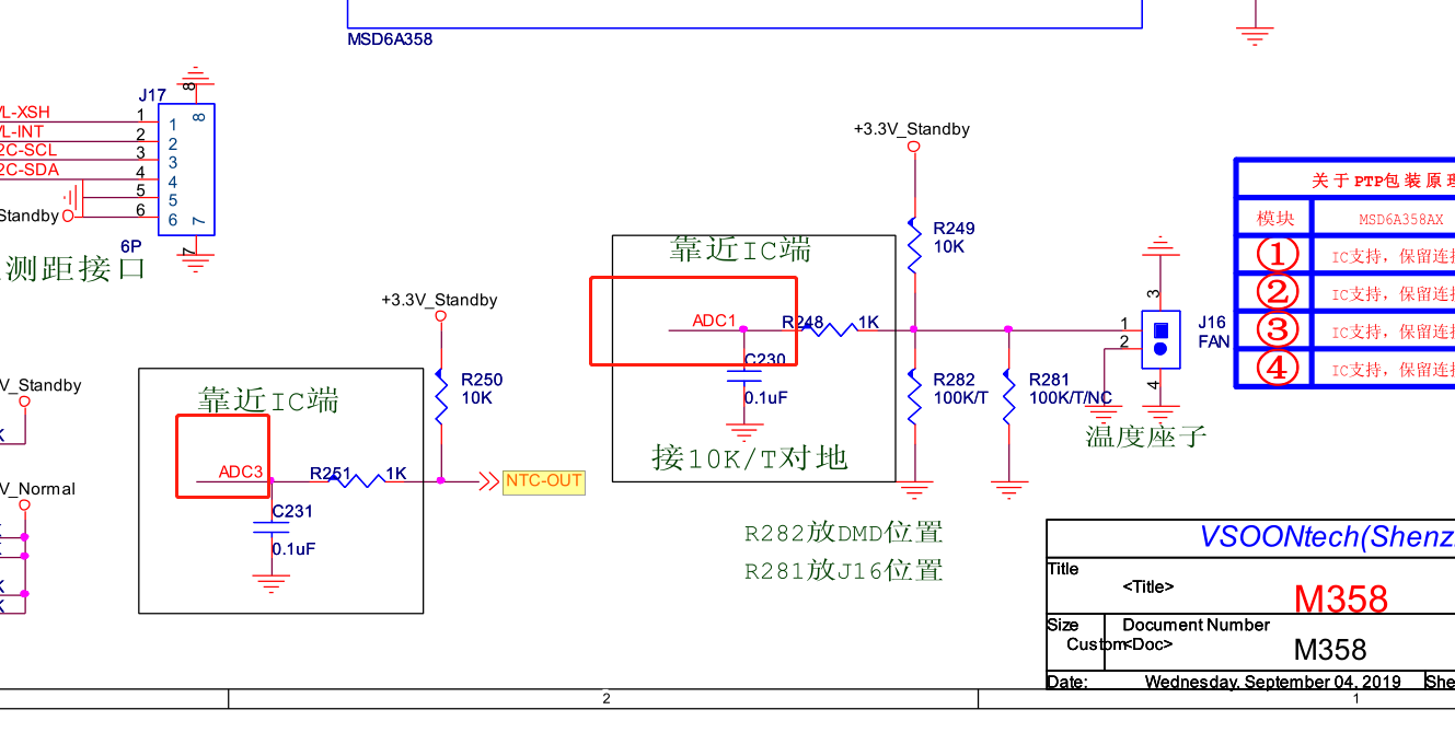
There are two thermistors on the hardware, ADC1 and ADC3 to collect temperature information respectively. ADC3 is used to measure the optical and mechanical temperature. Refer to Murata thermistor NCP15WF104F03RC.pdf for the comparison table of temperature and resistance; ADC1 is located on the main board of DMD. Refer to thermistor 100k_3950_101203.xls for the comparison table.
PhoneWindowManager.java has an interface to read ADC values. Here, ADC3 has been debugged to obtain the optical machine temperature as an example:

How to convert the voltage value read by ADC3 into thermistor voltage value and thermistor temperature value?
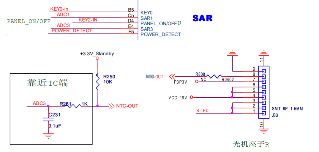
According to the above circuit, the thermistor is connected in series with R250 to divide the voltage of 3.3V (measured 3.317V). The voltage at both ends of the thermistor is U=3.3*Rw/(R250+Rw). When the external temperature changes, the main chip collects the changed voltage value through ADC3 (SAR3 port) and deduces the current temperature.
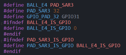
SAR3 pin configuration
Definition of pin pin of E4:
mst358\vendor\mstar\mboot\MBoot\sboot\inc\mainz\board\chip\MSD93AEGM8.h

SAR3 port definition:
mst358\vendor\mstar\mboot\MBoot\sboot\inc\mainz\board\BD_MST142B_10A_MAINZ.h

After mboot defines the sar3 port, you can use the following interface to obtain the adc value.
//-------------------------------------------------------------------------------------------------
/// Set SAR as ADC channel.
/// @ingroup G_SAR_COMMON
/// @param u8Channel: sar ADC channel 0~7
/// @param bEnable: 1: configured as ADC, 0: configured as GPIO input
/// @return E_SAR_ADC_OK: Success
/// @return E_SAR_ADC_FAIL or other values: Failure
//-------------------------------------------------------------------------------------------------
SAR_AdcResult MDrv_SAR_Adc_Config(MS_U8 u8Channel,MS_BOOL bEnable);

//-------------------------------------------------------------------------------------------------
/// Get ADC value function for each SAR channel.
/// @ingroup G_SAR_COMMON
/// @param u8Channel: sar ADC channel 0~7
/// @return MS_U8: ADC value
//-------------------------------------------------------------------------------------------------
MS_U8 MDrv_SAR_Adc_GetValue(MS_U8 u8Channel);
MDRV can be used directly in mboot and kernel_ SAR_ Adc_ Getvalue() to obtain the ADC value of a channel. Note that only 8-bit values can be returned. For SAR 3, MDRV is used directly_ SAR_ Adc_ GetValue (3) to get the ADC value. With ADC value, the next step is to establish a functional relationship with temperature.
Resistance value of thermistor
As the thermistor is a variable resistor, we need to measure the resistance before calculating the temperature, but we can't measure the resistance directly, we can only measure the voltage. Use the voltage divider circuit to collect and measure the voltage between the thermistor and the known resistance. The formula of the voltage divider is:

For the voltage divider in the thermistor circuit, the variables in the above equation are:

This equation can be rearranged and simplified to solve R2, the resistance of thermistor:
R2=(R1*Vout)/(Vin-Vout)
The circuit brought into this project, where R1=10K, Vin=3.3V, Vout is collected by SAR 3. Namely:
R2=(10K x Vout )/(3.3V- Vout).
Temperature calculation, Steinhart Hart equation and B-value method
reference resources:
https://baijiahao.baidu.com/s?id=1620021463882312794&wfr=spider&for=pc
https://wenku.baidu.com/view/e2f53c4c2f3f5727a5e9856a561252d380eb2092.html
https://blog.csdn.net/kezunhb/article/details/86631695
Use Steinhart Hart equation or B-value calculation method to convert the resistance value of thermistor into temperature reading.
-
Steinhart Hart equation calculation method:
1/T = A + B•ln® + C•[ln®]
Here: T is the absolute temperature, K (Kelvin temperature), and R is in ohms -
Calculation method of temperature coefficient B value:
R = R(25℃)•exp[B•(1/T - 1/298.15)]
Here: T is the absolute temperature K (Kelvin temperature), and R(25 ℃) is the resistance value of thermistor at 25 ℃ (unit: Ω) -
Temperature calculation formula realized by C language
Tsteinhart = 1/(A+Blog(Rth)+Cpow(log(Rth),3))-273.15;
Tbeta = 1/(1/(273.15+25)+1/Beta*log(Rth/R25))-273.15;
The temperature coefficient B value calculation method is used below. Murata thermistor NCP15WF104F03RC.pdf includes:

In other words, at 25 degrees, R25=100K, and the Beta constant is selected according to the actual application scenario. Here, we choose 25 degrees ~ 85 degrees, that is, Beta=4311, which is substituted into the formula:
Tbeta = 1/(1/(273.15+25)+1/4311log(Rth/(100K)))-273.15
= 1/(1/298.15+1/4311log(Rth/(100K)))-273.15
Note:
Temperature coefficient calculation: NTC thermistor Calculator v1 0
https://www.etdev.net/data/attachment/forum/201901/ntc_calculator/
NTC thermistor calculator usage: https://www.etdev.net/thread-104-1-1.html
Using the above tools, Beta=4200 is calculated, and the calculated temperature is closer to the value in the mapping table of Murata thermistor NCP15WF104F03RC.pdf.
Differences between ln, log and lg in mathematical formula and c language:
reference resources: http://www.cplusplus.com/reference/cmath/
In mathematics, log is the sign of logarithm. The photo number and base number on the right (the above is the real number and the below is the base number) lg is the base number with 10 (for example, lg100=2) (lg is the common logarithm) ln is the base number with E (lne2=2) (LN is the natural logarithm, e=2.718281828459045...)
There are only two functions log and log10 in C language. The function log(x) represents the natural logarithm based on e, that is, ln(x) function. log10(x) the logarithm based on 10, i.e. lg(x). The logarithm with other numbers as the base is expressed by the bottom exchange formula: loga(b)=ln(b)/ln(a), which is expressed in C language as log(b)/log(a).

C code implementation (example)
//Conversion of voltage to temperature
int temp_data(void)
{
   float temp=0;
   float Rth=0;
   float R25=100000;
   float T25=273.15+25;
   float Beta=4200;
   float Ka=273.15;
   float vol=(float)((Get_Adc_Average())*(3.3/255));
   Rth=(10000*vol)/(3.3-vol);	//10000kΩ is R249 value
   temp=1/(1/T25+log(Rth/R25)/Beta)-Ka+0.5;	//+0.5 is error correction
   return temp;
}
Implementation in Java code (example)
    private short mOldAdcValueDMD=0;
	private short mDMDTemperatureValue=0;
	private short getDMDTemperature(short adcValue){
		if(adcValue == mOldAdcValueDMD
			|| adcValue == (mOldAdcValueDMD - 1)
			|| adcValue == (mOldAdcValueDMD + 1)){
			return mDMDTemperatureValue;
		}

		short DMDtemp = 0;
		float Rth=0;
		float R25=100000;
		float T25=(float)273.15+25;
		float Beta=3950;
		float Ka=(float)273.15;
		float vol=(float)(adcValue*(3.3/255));
		Rth=(float)((10000*vol)/(3.3-vol));		//10000kΩ is R249 value
		DMDtemp=(short)(1/(1/T25+MathUtils.log(Rth/R25)/Beta)-Ka+0.5);	//+0.5 is error correction

		mDMDTemperatureValue=(short)DMDtemp;
		mOldAdcValueDMD = adcValue;

		return mDMDTemperatureValue;
    }
Then, the software is integrated according to the above method, but it is found that the optical mechanical temperature SAR3 detection voltage is always 3.3V, while the SAR1 detection voltage changes. After analyzing the hardware, I replied that the optical machine does not use thermistors (the hardware needs to be modified: remove the pull-up resistor R250 and paste R800 as 0 Ω), but uses S-5813A/5814A series temperature sensor IC. Refer to S5813A_5814A_E.pdf for the specification.. The internal principle of this chip may be to convert the voltage of thermistor into the voltage value of linear output:
Ta = -30 ° C: 2.582 V typ
Ta = +30 ° C: 1.940 V typ
Ta = +100 ° C: 1.145 V typ
Y=ax+b
2.582=a*(-30)+b
1.940=a*(30)+b
1.145=a*(100)+b
The first and second calculation results are as follows:
A=-0.0107
B=2.261
The second and third calculations show that:
a=-0.011356
b=2.2806
Calculated from the first and third parts:
A=-0.011054
B=2.2504
Because the voltage value converted by S-5813A is not completely linear, in order to reduce the error, the temperature is calculated in two intervals:
The first interval is - 30 ° ~ 30 °, Vol=-0.0107Ta+2.261, then Ta=(2.261-Vol)/0.0107
The second interval is 30 ° ~ 100 °, Vol=-0.011356Ta+2.2806, then Ta=(2.2806-Vol)/0.011356
Implementation in Java code (example)
	private short mOldAdcValueRay=0;
	private short mRayTemperatureValue=0;
	private short getRayTemperature(short adcValue){
		if(adcValue == mOldAdcValueRay){
			return mRayTemperatureValue;
		}

		float vol=(float)(adcValue*(3.3/255));
		if(vol > 2.6)
			return mRayTemperatureValue;
		else if(vol < 1.150)
			return mRayTemperatureValue;

		float Raytemp = 0;
		if(vol < 1.940){	//30°~100°
			Raytemp = (float)((2.2806-vol)/0.011356);
		}else{	//-30°~30°
			Raytemp = (float)((2.261-vol)/0.0107);
		}
		Log.d(TAG, "getRayTemperature()  adcValue="+adcValue+" vol="+vol+" Raytemp="+Raytemp);

		mRayTemperatureValue = (short)Raytemp;
		mOldAdcValueRay = adcValue;

		return mRayTemperatureValue;
	}
Test:
Internal temperature of optical machine (SAR3):

The output voltage of S-5813A measured with a multimeter is also 1.74V. Because the optical machine is sealed and cannot be disassembled, it is necessary to read the temperature value of the optical machine with I2C to judge the error.
External temperature of optical machine (thermistor detection), i.e. DMD temperature (SAR1):

Finally, the test results are corrected with a temperature measuring instrument.
other
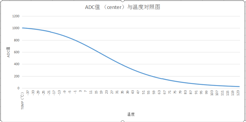
The above is to use the formula to convert the ADC value to the temperature value. Another method is to make two table values. Table 1 is the ADC value, and table 2 is to read the optical mechanical temperature value through I2C. The two tables can customize the optical mechanical temperature curve, and then integrate the data of the two tables into the code. This method is relatively more accurate to obtain the temperature value. The disadvantage is that the code portability is poor and the optical machine may be burned when collecting the optical machine temperature value.
