This article is regarded as the last article [optimization of global registration between G2O and multi view point cloud] Continuation of.
As we know from the previous article, we now have the registered global point cloud, the transformation matrix of each point cloud and the RGB image corresponding to each point cloud. Next, it is natural to reconstruct the 3D mesh of the global point cloud and texture map the reconstructed 3D mesh.
Known: 3D model (triangular patch, arbitrary format), multi view RGB picture (texture), transformation matrix; Request: paste texture map for 3D model.
For the above texture to be solved, the familiar little partner must know that he is actually in the last step of solving multi view stereo matching - Surface Reconstruction and texture generation.
Next, in order to achieve our goal, we first need to reconstruct the triangular mesh from the point cloud, which has nothing to do with the camera and texture pictures. We can directly use the reconstruction interface in pcl or cgal or even meshlab software to reconstruct the triangular mesh from the three-dimensional point cloud.
Before completing the reconstruction of triangular mesh, there is still a very important -- but a key step that can be omitted as appropriate: multi view 3D point cloud fusion! Let's continue to use the 8 point cloud clips we shot before as an example for example recording. (note that the emphasis on 8 point cloud segments here does not mean the point cloud of 8 perspectives, which will be explained later).
Multi view point cloud fusion
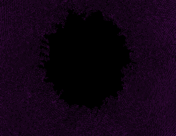
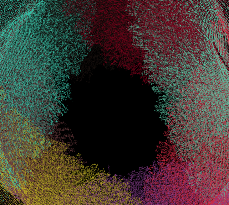
After splicing multiple point cloud segments, it is inevitable that point clouds overlap each other from multiple perspectives. As shown in the following figure, the density of point clouds in overlapping areas is generally greater than that in non overlapping areas. The first purpose of point cloud fusion is to remove the duplicate of point cloud and reduce the amount of point cloud data; The second is to further smooth the point cloud, improve the accuracy and provide high-quality data for other subsequent calculations (such as measurement).
Coincidentally, I have a certain understanding of the moving least squares algorithm. In pcl, N years ago[ MLS smoothing of pcl ]And[ The MLS algorithm of pcl calculates and unifies the normal vector ]I also did some small tests. In my impression, moving least squares works like this: for in-depth data, calculate the target point and its neighborhood. These local data to be calculated constitute the compact support region of the target point. In the compact support region, a function operates on the target point. The basic rule of operation is based on the different weights from other points in the compact support region to the target point, A function here is the so-called compactly supported function. Compactly supported function + compactly supported domain + weight function constitute the basic mathematical concept of mobile least squares algorithm. The so-called mobility is reflected in the "sliding" calculation of compactly supported domain in the allowable space until all data are covered. Least squares generally aims at the global optimization, while mobile least squares can not only solve the global optimization, but also have local optimization due to its "mobility" (tight support). Further, for 3D point cloud, it can extract isosurface and realize the reconstruction of surface triangular mesh combined with MC (mobile cube) algorithm.
In pcl, there are many examples of MLS algorithm. My previous two hydrology articles also have a basic application introduction. There are not too many records here. Here, use the following code directly:
pcl::PointCloud<pcl::PointXYZRGB> mls_points; //Save results
pcl::search::KdTree<pcl::PointXYZRGB>::Ptr tree(new pcl::search::KdTree<pcl::PointXYZRGB>);
pcl::MovingLeastSquares<pcl::PointXYZRGB, pcl::PointXYZRGB> mls;
mls.setComputeNormals(false);
mls.setInputCloud(res);
mls.setPolynomialOrder(2); //The order of MLS fitting,
mls.setSearchMethod(tree);
mls.setSearchRadius(3);

mls.setUpsamplingMethod(pcl::MovingLeastSquares<pcl::PointXYZRGB, pcl::PointXYZRGB>::UpsamplingMethod::VOXEL_GRID_DILATION);
mls.setDilationIterations(0);  //Set voxel_ GRID_ Number of iterations of division method

mls.process(mls_points);
Note that pcl:: movingleastsquares:: voxel is used in the above calculation_ GRID_ According to the official interpretation of pcl, this method can not only repair a small number of point cloud holes, but also locally optimize the point cloud coordinates and output the point cloud with the same global density. By setting different iteration times, this method can not only reduce sampling, but also up sampling (mainly controlled by iteration times)
Put your own data into the above calculation process, and the local effect of point cloud fusion is as follows:
 |
The visible point cloud is more uniform and smooth. At the same time, the amount of data is reduced from 100w + to 10w +
The above operations basically meet the requirements of the next step.
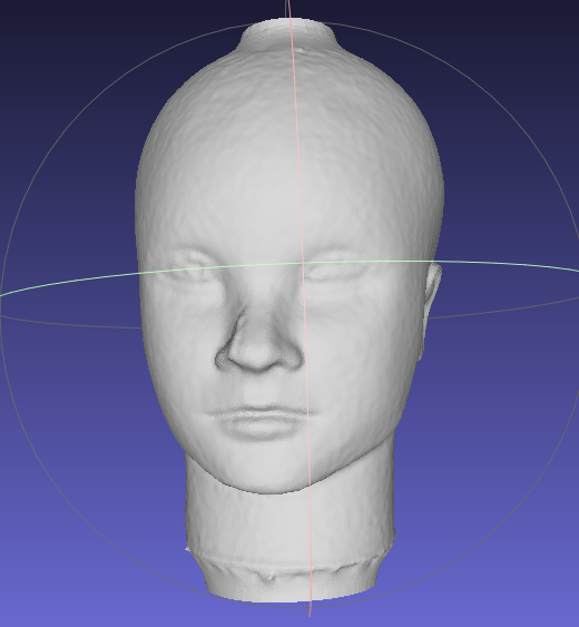
Further, since the surface reconstruction is not the focus, for the above results, Poisson reconstruction in MeshLab software is directly used here, and the results are recorded as follows:
Multi view texture mapping
Here, I formally introduce my understanding of the so-called "multi perspective".
First of all, multi angle and multi angle. Usually, these two concepts basically mean the same thing, that is, shooting three-dimensional models from different azimuth angles. But there are two different modes of operation, such as hand held 3D scanner, state estimation in SLAM, even equipped with camera / Radar autopilot and so on. These scenes are basically cameras moving and target moving, that is, camera moving around the target. Second, such as rotary table 3D scanner, these scenes are basically the camera does not move and the target moves, that is, the target itself has motion attributes. Therefore, it is necessary to further distinguish between multi angle and multi angle. Multi angle refers to the multi angle of the camera (yes, the camera has the real physical angle, pose, shooting angle, balabalabala...), Multi angle refers to the different angles of the target object (yes, an object can be observed from different angles).
Secondly, external parameter, external parameter is a very important concept (nonsense, use you!), Can it really attract enough attention from other users? Not necessarily! The external parameter we often say is actually with a subject, but we are too used to it and omit the subject. External parameters --- generally refers to the external parameters of the camera, that is, to describe the changes of the camera. In multi view 3D point cloud registration, each point cloud has a change matrix, which can be called the external parameter of point cloud, that is, to describe the change of point cloud. So far, there are at least two external parameters, and the two external parameters represent completely different physical meanings, but they are inextricably linked. As we all know, the macroscopic downward motion is mutual, so the external parameters of the point cloud and the corresponding camera must be mutually inverse.
Note: the reason why the above concepts are strictly distinguished here is mainly because I didn't really understand the concepts mentioned above before, especially the understanding of external parameters, which led to errors in later algorithm calculation; Second, the following libraries and frameworks strictly distinguish the above.
OpenMVS and texture mapping
Finally came to OpenMVS....
It is known that OpenMVS can be used for dense reconstruction (point cloud), Mesh reconstruction (point cloud -- > Mesh), Mesh optimization (non popular processing, hole filling, etc.) and Mesh texture mapping, which exactly corresponds to several apps of the source code.
Here, the purpose is simply to need the mesh texture mapping function of OpenMVS! Browse the usage methods of OpenMVS at home and abroad, especially in China, Basically, they are all "one-stop" services. The summary process is colmap/OpenMVG/visualSFM...+ OpenMVS. Basically, they use executable files in a fool's way (check a lot on the Internet), and they are basically repeated "reference" (plagiarism), which obviously does not meet their own requirements and purposes. Spit a slot...
In order to use the texture mapping module of Openmvs, the input data must be mvs format file, amount What the hell is mvs? I don't have it. What should I do?!
Well, enter the OpenMVS source code and fill the data interface required by OpenMVS with your own data. (Window10 + VS2017+OpenMVS compilation is omitted, mainly because they did not make records when compiling, but CMake project is generally not too complex).
Scene
Check several examples provided with OpenMVS and find that it must fill in the Scene class. For the problems you face, the main structure of the Scene class is as follows:
class MVS_API Scene
{
public:
    PlatformArr platforms; //camera platforms, each containing the mounted cameras and all known poses
    ImageArr images; //Texture map, corresponding to camera / / images, each referencing a platform's camera pose
    PointCloud pointcloud; //Point cloud / / point cloud (spark or deny), each containing the point position and the views seeing it
    Mesh mesh; //Mesh, represented as vertices and triangles, constructed from the input point cloud

unsigned nCalibratedImages; // number of valid images

unsigned nMaxThreads; // maximum number of threads used to distribute the work load

... //Omit code

bool TextureMesh(unsigned nResolutionLevel, unsigned nMinResolution, float fOutlierThreshold=0.f, float fRatioDataSmoothness=0.3f, bool bGlobalSeamLeveling=true, bool bLocalSeamLeveling=true, unsigned nTextureSizeMultiple=0, unsigned nRectPackingHeuristic=3, Pixel8U colEmpty=Pixel8U(255,127,39));

... //Omit code

}
The main function you need is bool TextureMesh(). It can be seen that it comes with many parameters. The significance of the parameters will be discussed later.
Platforms
First, let's look at platforms, which is an array of platforms. In OpenMVS, the Platform is defined as follows:
class MVS_API Platform
{
...

public:
    String name; // platform's name
    CameraArr cameras; // cameras mounted on the platform
    PoseArr poses;

...

}
For us, we must fill two arrays, CameraArr and PoseArr.
CameraArr is an array of type CameraIntern. CameraIntern is the most basic camera parent class. When a camera is mentioned, it must contain two matrices: internal parameter and external parameter. CameraIntern is no exception. It needs to be filled with the following three parameters, in which K is the normalized internal parameter of 3X3 camera, which can be filled with the matrix in Eigen, so-called normalization, In fact, each element of the internal parameter matrix is divided by the maximum width or height of the texture image; As the name suggests, R represents the rotation of the camera, C represents the translation of the camera, and R and C together constitute the external parameters of the camera.
    KMatrix K; //the intrinsic camera parameters (3x3)
    RMatrix R; //External parameters: camera rotation (3x3) and
    CMatrix C;
PoseArr is an array of type pose. Pose is a structure defined in the Platform class:
struct Pose {
        RMatrix R; // platform's rotation matrix
        CMatrix C; // platform's translation vector in the global coordinate system
        #ifdef _USE_BOOST
        template <class Archive>
        void serialize(Archive& ar, const unsigned int /*version*/) {
            ar & R;
            ar & C;
        }
        #endif
    };
    typedef CLISTDEF0IDX(Pose,uint32_t) PoseArr;
It can be seen from the above pose that it also contains two matrices, but the physical meaning of the matrix in pose here is completely different from that of the parameters in CameraIntern. In short, < font color = Red > CameraIntern represents the inherent or inherent attributes of the camera itself, Pose represents the pose matrix of the whole Platform (including the camera) in the world coordinate system. For each texture map (described below), these two attribute parameters together constitute the real external parameter of the corresponding camera < / font > (explained later through the source code) [question 1].
Images
images is an array of ImageArr type. As explained in the source code, each Image corresponds to each camera pose. The structure of Image is as follows:
class MVS_API Image
{
public:
    uint32_t platformID;//ID corresponding to the platform / / ID of the associated platform
    uint32_t cameraID; // ID of the associated camer a on the associated platform
    uint32_t poseID; // Pose ID / / ID of the pose of the associated platform
    uint32_t ID; // global ID of the image
    String name; // The path of the imgage / / image file name (relative path)
    Camera camera; // view's pose
    uint32_t width, height; // image size
    Image8U3 image; //It has been handled when load ing image color pixels
    ViewScoreArr neighbors; // scored neighbor images
    float scale; // image scale relative to the original size
    float avgDepth;

    ....

}
As in the above Chinese notes added by yourself, the three parameters < font color = Red > platformid, cameraID and poseID must strictly correspond to the member attributes in the Platform < / font >, which are the three most important parameters for themselves. The member variables in the Platform do not carry the ID attribute, but are sorted by default according to the addition order, and the ID index increases from 0.
In the Image structure, there is also a camera member that must be mentioned. As noted in the source code, it represents the pose of the camera, that is, which camera corresponds to the picture. At first glance, the camera member must also be filled, but this is not the case. The reason will be explained later [question 2].
Other members in the structure, such as image width and height, image name, etc., call Image::LoadImage(img_path); Function will be automatically filled in when it is used; The neighbors member represents the adjacency of the image to 3D points. It is not a necessary option in texture mapping, and does not affect the effect of texture mapping.
PointCloud
This member represents the point cloud, which is generally the result of sparse reconstruction or dense reconstruction of OpenMVS. It has no constraints on the grid and is directly discarded without filling.
Mesh
For the triangular mesh storage structure in OpenMVS, I only need to know that it has a Load function.

