OSPF neighbor adjacency
Principle overview:
In ospf network, the router must establish a correct OSPF neighbor relationship before sending any link state information.
OSPF router uses Hello message to establish neighbor relationship. OSPF router will check various parameters in the received Hello message, such as router ID, area ID, authentication information, netmask, hello interval, etc. If these parameters are consistent with the corresponding parameters configured on the receiving interface, the neighbor relationship will be established, otherwise the neighbor relationship cannot be established.
After the neighbor relationship of OSPF router is established, the next step is to establish the neighbor relationship. Not all OSPF neighbors can establish adjacency relationships, which depends on the network type between OSPF neighbors. For example, in a point-to-point network, an effective OSPF neighbor relationship can further form an adjacency relationship. On the broadcast network, post election DR and BDR; DR and BDR will establish adjacency relationship with all other routers, all other routers will establish adjacency relationship, and all other routers will only establish adjacency relationship with Dr and BDR.
Purpose of the experiment:
Understand the meaning and difference of OSPF neighbor relationship and OSPF neighbor relationship
Observe the establishment process of OSPF neighbor adjacency relationship
Observe the synchronization process of OSPF link state database
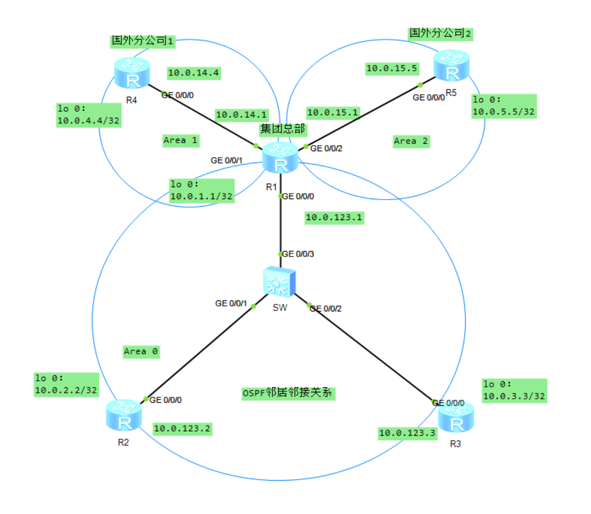
Start the experiment; The experimental topology is shown in the figure:
1: First, configure the interface address and network protocol:
R1:

#

interface GigabitEthernet0/0/0

 ip address 10.0.123.1 255.255.255.0

#

interface GigabitEthernet0/0/1

 ip address 10.0.14.1 255.255.255.0

#

interface GigabitEthernet0/0/2

 ip address 10.0.15.1 255.255.255.0

#

interface NULL0

#

interface LoopBack0

 ip address 10.0.1.1 255.255.255.255

#

ospf 1

 area 0.0.0.0

  network 10.0.1.1 0.0.0.0

  network 10.0.123.0 0.0.0.255

 area 0.0.0.1

  network 10.0.14.1 0.0.0.0

 area 0.0.0.2

  network 10.0.15.1 0.0.0.0

R2:
#

interface GigabitEthernet0/0/0

 ip address 10.0.123.2 255.255.255.0

#

interface GigabitEthernet0/0/1

#

interface GigabitEthernet0/0/2

#

interface NULL0

#

interface LoopBack0

 ip address 10.0.2.2 255.255.255.255

#

ospf 1

 area 0.0.0.0

  network 10.0.2.2 0.0.0.0

  network 10.0.123.0 0.0.0.255

R3:
#

interface GigabitEthernet0/0/0

 ip address 10.0.123.3 255.255.255.0

#

interface GigabitEthernet0/0/1

#

interface GigabitEthernet0/0/2

#

interface NULL0

#

interface LoopBack0

 ip address 10.0.3.3 255.255.255.255

#

ospf 1

 area 0.0.0.0

  network 10.0.3.3 0.0.0.0

  network 10.0.123.0 0.0.0.255

R4:

#

interface GigabitEthernet0/0/0

 ip address 10.0.14.4 255.255.255.0

#

interface GigabitEthernet0/0/1

#

interface GigabitEthernet0/0/2

#

interface NULL0

#

interface LoopBack0

 ip address 10.0.4.4 255.255.255.255

#

ospf 1

 area 0.0.0.1

  network 10.0.4.4 0.0.0.0

  network 10.0.14.4 0.0.0.0

R5:
#

interface GigabitEthernet0/0/0

 ip address 10.0.15.5 255.255.255.0

#

interface GigabitEthernet0/0/1

#

interface GigabitEthernet0/0/2

#

interface NULL0

#

interface LoopBack0

 ip address 10.0.5.5 255.255.255.255

#

ospf 1

 area 0.0.0.2

  network 10.0.5.5 0.0.0.0

  network 10.0.15.0 0.0.0.255
After configuration, explain here:
This experiment simulates a multinational enterprise network scenario. The routers R1, R2 and R3 of the domestic group headquarters form a broadcast network, the router R4 of foreign branch 1 and the core router R1 of the domestic group headquarters form a point-to-point network, and the router R5 of foreign branch 2 and the core router R1 of the domestic group headquarters form another point-to-point network.
2: We have configured OSPF protocol on each router. As shown in the figure at the beginning, we can also see that the link between R1, R2 and R3 belongs to area 0, the link between R1 and R4 belongs to area 1, and the link between R1 and R5 belongs to area 2.
The configuration command is shown above;
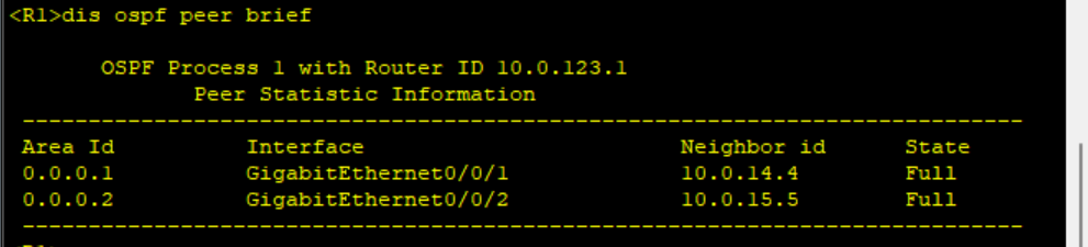
After the configuration is completed, check the OSPF neighbor establishment of R1:

It can be seen that the OSPF neighbor relationship of R1 is FULL, indicating that the neighbor neighbor relationship has been successfully established. View the details of OSPF neighbor status on R1;
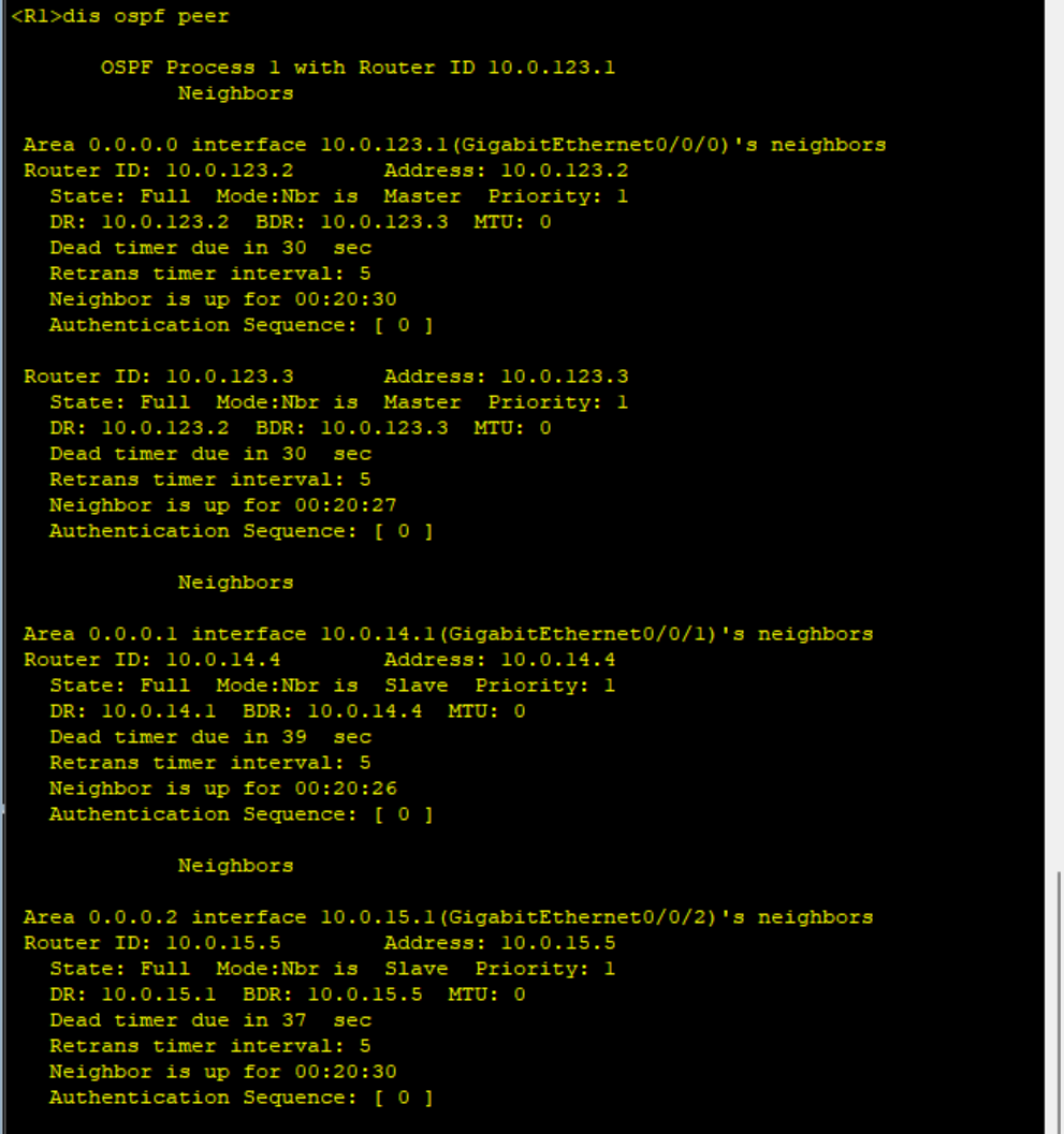
It can be seen that the broadcast network including R1, R2 and R3 has completed the election of DR/BDR. The election results are shown in the figure. 10.0.123.2 (R2) is Dr and 10.0.123.3 (R3) is BDR. The two point-to-point networks between R1 and R4 and between R1 and R5 did not conduct DR/BDR election.
View the details of broadcast network interface G0/0/0 and point-to-point network interface G0/0/1 on R1
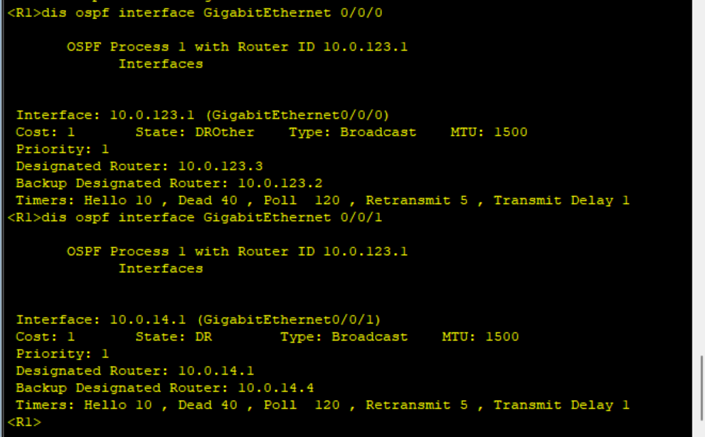
It can be seen that the default Hello interval of broadcast network interface and point-to-point network interface is 10s and the failure time is 40s.
3: Observe the establishment process of OSPF neighbor adjacency relationship
Firstly, the process of establishing OSPF neighbor adjacency relationship on broadcast network is observed. In order to clearly observe the establishment process of OSPF neighbor adjacency relationship on R1, first close G0/0/0 and G0/0/1 interfaces on R1.
[R1]int g0/0/1

[R1-GigabitEthernet0/0/1]sh

[R1-GigabitEthernet0/0/1]shutdown

[R1-GigabitEthernet0/0/1]int g0/0/2

[R1-GigabitEthernet0/0/2]sh

[R1-GigabitEthernet0/0/2]shutdown
Then, view OSPF neighbor relationship on R1
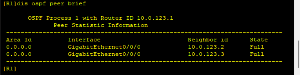
It can be seen that the neighbor relationship of R1, R2 and R3 is Full, indicating that the neighbor relationship has been established.
Now restart the OSPF process on R1 and observe the establishment process of OSPF adjacency relationship between R1 and R2 through Debugging.
[R1]int g0/0/0

[R1-GigabitEthernet0/0/0]ospf dr-priority 0


[R2]int g0/0/0

[R2-GigabitEthernet0/0/0]ospf dr-priority 0
After restarting OSPF processes on R1 and R2, first check OSPF neighbor establishment on DR router R3
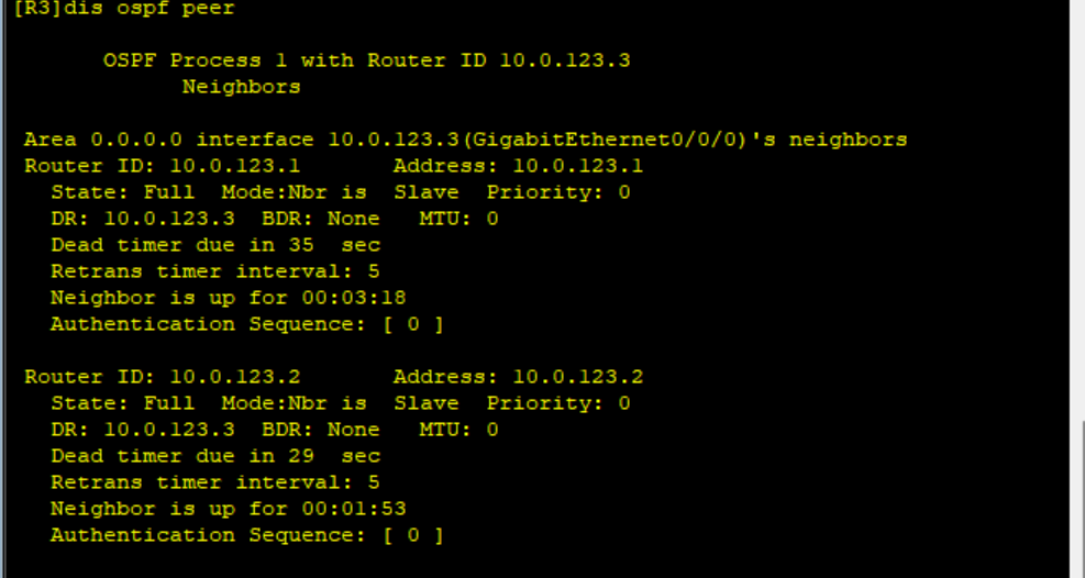
It can be seen that R3 is DR, there is no BDR in the network, and R3 has established adjacency relationship with R1 and R2 respectively.
Check OSPF neighbor relationship establishment on router R1.
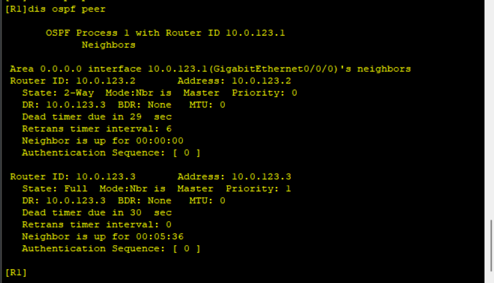
It can be seen that R1 has established an adjacency relationship with DR router R3, and the state is FULL, while it has only established a neighbor relationship with DRouthers router R2, and the state is 2-Way.
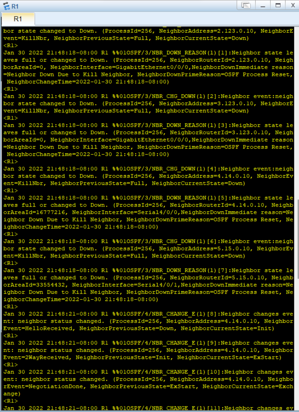
Restart the OSPF process on router R1 and observe the establishment process of OSPF neighbor relationship through Debugging.
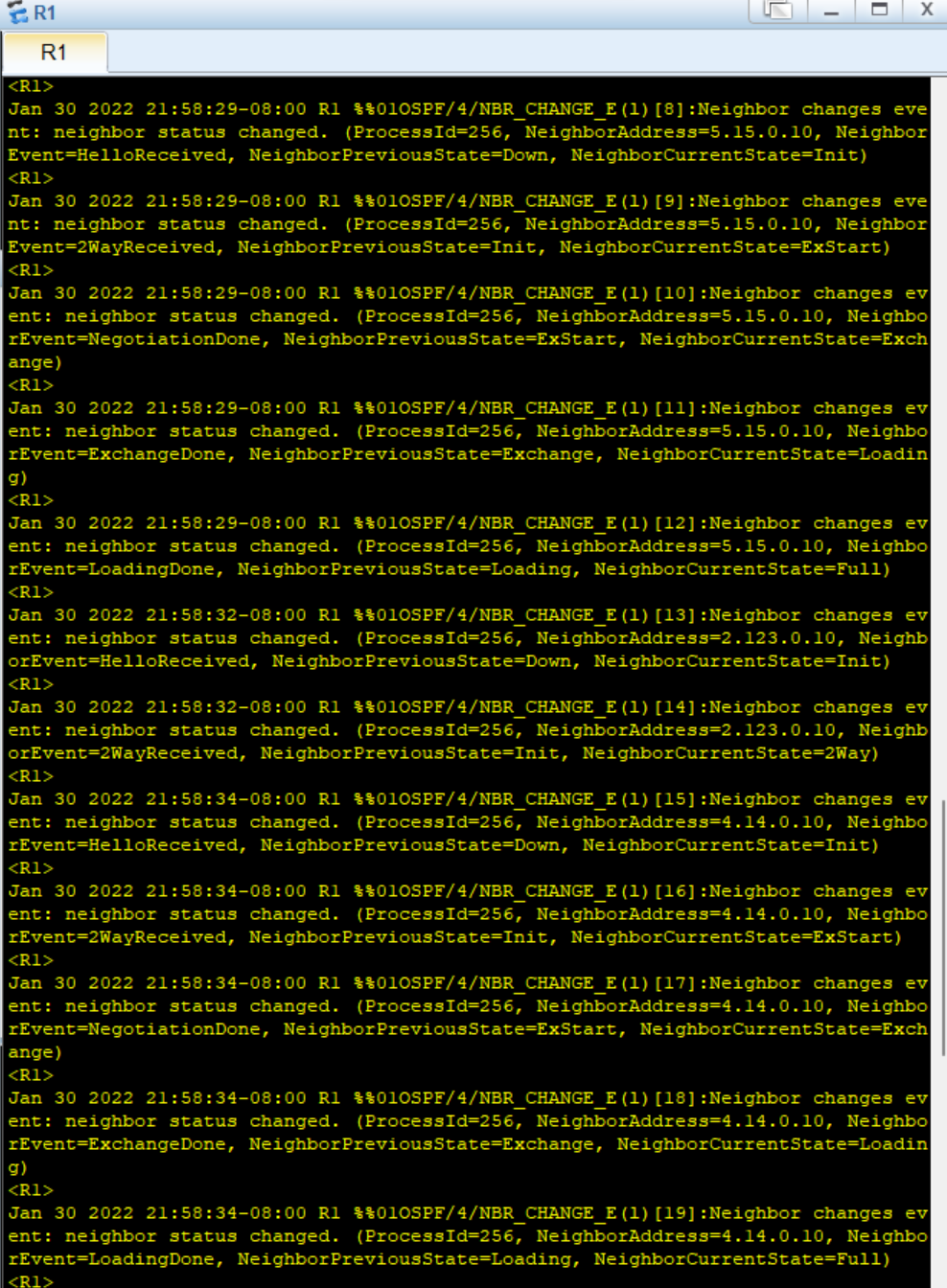
The experiment observed the establishment of OSPF neighbor relationship in point-to-point network, and opened two interfaces G0/0/1 on R1
G0/0/2
[R1]int g0/0/1

[R1-GigabitEthernet0/0/1]un sh

[R1-GigabitEthernet0/0/1]un shutdown

[R1-GigabitEthernet0/0/1]int g0/0/2

[R1-GigabitEthernet0/0/2]un sh

[R1-GigabitEthernet0/0/2]un shutdown
Then, check OSPF neighbor establishment on R1
4: Observe the synchronization process of OSPF link state database
Check the message
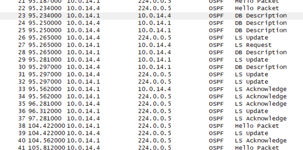
From the figure, we can observe various data packets of OSPF protocol, which reflect the synchronization process of LSDB and the process of establishing OSPF neighbor relationship: first, R1(10.0.14.1) and R4(10.0.14.4) negotiate through Hello message, and then through DD: database description message and LSR:Link State Ruquest message, The LSU (link state update) message finally realizes the synchronization of LSDB and establishes the OSPF adjacency relationship.
Let's analyze the Hello messages sent by R1 and R4:
NO.21(Hello message):

NO.22(Hello message):
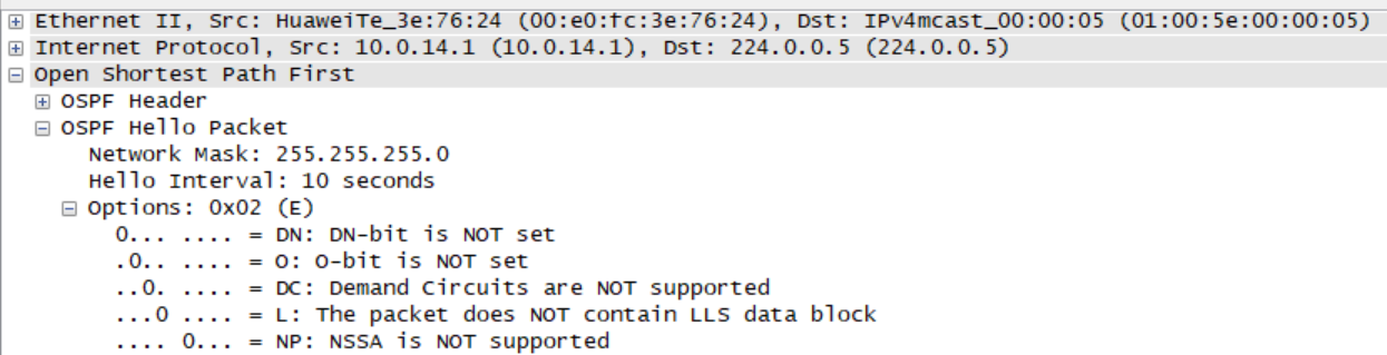
It can be seen that the Hello message contains a lot of basic information. For example, the subnet mask is 24 bits, the Hello interval is 10s, the router death interval is 40s, and there are no DR and BDR on the network. In addition, the Hello message released by R4 indicates that the active neighbor is R1, which indicates that R1 and R4 have successfully established OSPF neighbor relationship;
NO.23(DD message):
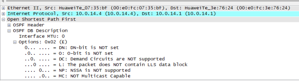
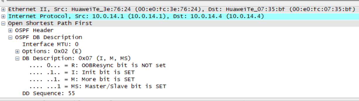
NO:24(DD message):
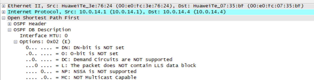
It can be found that the DD message interacted for the first time, in which one bit, M bit and MS bit are set to 1. Both R1 and R4 claim to be the main router. These two DD messages do not contain database summary information. After the first DD message interaction, R4 with larger router ID can be selected as the main router.
Remarks: if there is any error, please understand!
This article is my study notes, for reference only! If repeated!!! Please contact me!