ESP822 chip is a development board that can be used as both server and client. When ESP8266 is selected as the client, you can connect to WIFI for network request. After the network is configured, you can use https to request related API s.
First show the results:
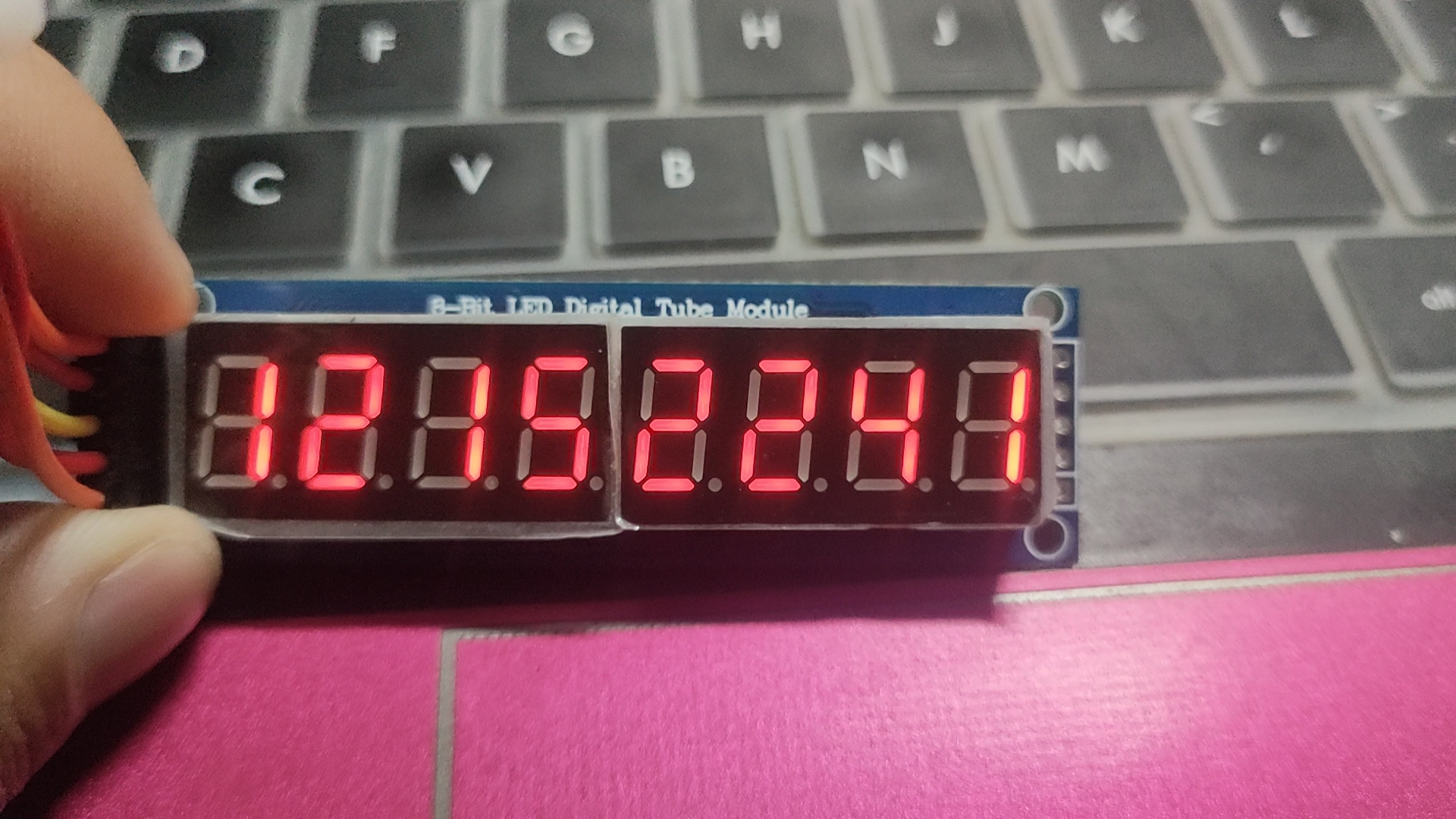
As shown in the figure above, it is 22:41 on December 15
Step 1: drive nixie tube
1. The eight digit nixie tube is a common anode nixie tube controlled by two 595 chips in cascade. The circuit diagram is as follows.
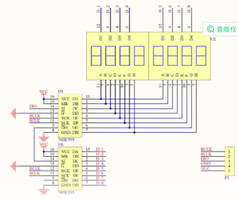
The eight digit nixie tube corresponds to eight bits. When each bit is written to the high level, it is equivalent to selecting the corresponding nixie tube to light up. When the speed is fast enough, the human naked eye will not distinguish the flickering effect. For example, 0000 0001 is to select the rightmost nixie tube to display the number. After being elected to the middle position, the eight digit segment selection is carried out, that is to control what numbers are displayed by the nixie tube. Each nixie tube is essentially composed of eight led lamps. Because it is a common anode nixie tube, the led will light up when writing low level. For example: write 1001 1111, and the nixie tube will display the number "1". When 0000 0001 1001 1111 is written, the rightmost nixie tube will be lit and the number "1" will be displayed. As for how the nixie tube works and how the nixie tube displays the corresponding numbers, it is not the focus of this article. It is suggested that Baidu can know in more detail.
The code is as follows:
//595 nixie tube module
void DTSMG(u16 buff)
{
  int i;
  digitalWrite(4,LOW);//Pull low level
  for(i=0;i<=15;i++) //Loop writes 16 bit binary numbers into two concatenated 595
  {
    digitalWrite(5,LOW);//Pull low level
    if(((buff>>i)&0x0001)==0) { digitalWrite(16,LOW);}//DIO to be scanned pin is low
    else if(((buff>>i)&0x0001)==1) { digitalWrite(16,HIGH);}//The pin to be scanned is high
    for(int j=0;j<1000;j++);
    digitalWrite(5,HIGH);//Shift binary information into 595

  }
  for(int j=0;j<1000;j++);
  digitalWrite(4,HIGH);//The 16 bit binary information is continuously output through 595
}
The above is the nixie tube control code.
The following is the code of ESP8266 as the client access API
#include <ESP8266WiFi.h>
#include <WiFiClientSecure.h>
#include <ESP8266WebServer.h>

#Define SSID "12345678" / / change 12345678 here to your own WiFi name
#define password "12345678" / / change 12345678 here to your WiFi password
//Test HTTPS communication website
const char *host = "***********";  //Replace here with the domain name you need to access
const int httpsPort = 443;  //Port 443 for HTTPS requests
char *ch3;/ /Used to store time data
int ad[8];
int x;
int h=0;

//Nixie tube data is 0,1,2,3,4,5,6,7,8,9
u16 shujubao[16]={0x03,0x9f,0x25,0x0d,0x99,0x49,0x41,0x1f,0x01,0x19};

  void setup() {
  Serial.begin(9600);    //set baud rate
  WiFi.mode(WIFI_STA);    //Set ESP8266 to wireless terminal working mode
  WiFi.begin(ssid, password); //Connect to target WiFi
  Serial.println("");
  Serial.println("Connecting"); Serial.println("");// Waiting for connection
  while (WiFi.status() != WL_CONNECTED) {   //WiFi.status() != WL_CONNECTED determines whether the connection is successful
    delay(500);   //delayed
    Serial.print(".");  //Loop out "." when the connection is not successful
  }
  Serial.println("");
  Serial.print("Connected to ");
  Serial.println(ssid);
  Serial.print("IP address: ");
  Serial.println(WiFi.localIP()); //After successful connection, the WiFi name and the IP address of ESP8266 are displayed through the serial port monitor.
  //Here are the three pins related to the configuration of ESP8266
  pinMode(4,OUTPUT);//D2   RCL
  pinMode(5,OUTPUT);//D1   SCL
  pinMode(16,OUTPUT);//D0
}

//{"sysTime2":"2021-12-26 13:58:02","sysTime1":"20211226135802"}
//The above is the data actually requested, and the valid information to be extracted is the 50th to 57th bits

void fang()
{
   https_connect(); // Realize HTTPS access communication
  for(int i=50;i<=57;i++)//The switch statement is used repeatedly to realize type conversion and convert useful information into int type
  {
switch(ch3[i])
{
case '0' : ad[i-50]=0;break;
case '1' : ad[i-50]=1;break;
case '2' : ad[i-50]=2;break;
case '3' : ad[i-50]=3;break;
case '4' : ad[i-50]=4;break;
case '5' : ad[i-50]=5;break;
case '6' : ad[i-50]=6;break;
case '7' : ad[i-50]=7;break;
case '8' : ad[i-50]=8;break;
case '9' : ad[i-50]=9;break;
}
  }

}

//Here is the part of the nixie tube that has been displayed circularly
void loop()
{

   if(h==9999){
   //Call request function
   fang();
   h=0;
   }
   h++;
   //1  0000 0001  1001 1111
    DTSMG((0x01<<8)+shujubao[ad[0]]);
    for(int j=0;j<1000;j++);//Delay here
    //2  0000 0010  0010 0101
    DTSMG((0x02<<8)+shujubao[ad[1]]);
    for(int j=0;j<1000;j++);
    //3  0000 0100  0000 1101
    DTSMG((0x04<<8)+shujubao[ad[2]]);
   for(int j=0;j<1000;j++);
    //4  0000 1000  1001 1001
    DTSMG((0x08<<8)+shujubao[ad[3]]);
    for(int j=0;j<1000;j++);
    //5  0001 0000  0100 1001
    DTSMG((0x10<<8)+shujubao[ad[4]]);
    for(int j=0;j<1000;j++);
    //6  0010 0000  0100 0001
    DTSMG((0x20<<8)+shujubao[ad[5]]);
    for(int j=0;j<1000;j++);
    //7  0100 0000  0001 1111
    DTSMG((0x40<<8)+shujubao[ad[6]]);
    for(int j=0;j<1000;j++);
    //8  1000 0000  0000 0001
    DTSMG((0x80<<8)+shujubao[ad[7]]);
    for(int j=0;j<1000;j++);

}

//Nixie tube module
void DTSMG(u16 buff)
{
  int i;
  digitalWrite(4,LOW);
  for(i=0;i<=15;i++)
  {
    digitalWrite(5,LOW);
    if(((buff>>i)&0x0001)==0) { digitalWrite(16,LOW);}//DIO
    else if(((buff>>i)&0x0001)==1) { digitalWrite(16,HIGH);}
    for(int j=0;j<1000;j++);
    digitalWrite(5,HIGH);

  }
  for(int j=0;j<1000;j++);
  digitalWrite(4,HIGH);
}


//Network call API function
void https_connect()
{
  //Create WiFiClientSecure object
  WiFiClientSecure httpsClient;
  //Serial monitor display domain name
  Serial.println(host);
  //Connection without authentication
  httpsClient.setInsecure();
  //Used to determine whether the connection timed out
  httpsClient.setTimeout(15000);
  delay(1000);    //delayed
  Serial.println("HTTPS Connecting");
  Serial.println("");
  int r=0;
  while((!httpsClient.connect(host,httpsPort)) && (r < 300))
  {
    // Try connecting to the server and wait
    delay(100);         //httpsClient.connect(host,httpsPort) is used to connect to the server
    Serial.print(".");
    r++;
  }
  if(r==30)
  {
    // After the connection timeout, the "connection failure" information is output and returned
    Serial.println("Connection failed");
    Serial.println(httpsClient.getLastSSLError());
    return;
  }
  else
  {
    Serial.println("Connected...");// If the connection is successful, the "connection successful" information is output
  }
  // Create HTTPS request information string
  //The ******************************************************************
  String request =  String("GET ")+"************"+" HTTP/1.1\r\n" +  //Request line
                 "Host: " + host + "\r\n" +   //Request header
                 "connection: close\r\n"+"\r\n";
  //  Send request to server
  httpsClient.print(request);
  Serial.println("request sent");
  // Inform the user that the current ESP8266 has successfully received the server response header information.
  while (httpsClient.connected())
  {
    // Check the server response information. Once the end character of the response header is found, the ESP8266 is informed through the serial port monitor that the server response header information has been successfully received.
    String line = httpsClient.readStringUntil('\n'); //Get response header information
    //The serial port monitor displays the response header information
    if (line == "\r")
    {
      //Determine whether the header ends
      Serial.println("headers received");
      break;
    }
  }
  // Output server response body information (server message) through serial port monitor
  Serial.println("Responder:");
  String body;
  while(httpsClient.available())
  {
    body= httpsClient.readStringUntil('}');    //Get response body information
    //Cast here
    char *ch2 = const_cast<char*>(body.c_str());
     Serial.println(body);
    ch3= ch2;
  }
  httpsClient.stop(); //After the operation, disconnect the server
  Serial.println("closing connection");
}
There are some things to pay attention to in the above code
1. First, change the WiFi name and WiFi password
2. The domain name and address need to be changed
3. The api request address needs to be changed
The network API for time requests that can be requested in the specific network can be searched by Baidu
The knowledge about esp8266 as a client https request used in this article is learned from "Taiji maker". I'm not very good at blogging for the first time. I hope you guys are righteous.