Spanning tree protocol: configure PVST + (Cisco 3.3.1.5)


Part 1: configuring VLAN s
Step 1: enable the user ports on S1, S2 and S3 in access mode.
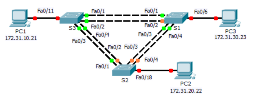
Referring to the topology diagram, determine which switch ports (S1, S2 and S3) are activated for end-user equipment access. These three ports will be configured for access mode and enabled using the "no shutdown" command.
S1(config)# interface f0/6

    switchport mode access

     no shutdown


S2(config)# interface f0/18

    switchport mode access

     no shutdown


S3(config)# interface f0/11

    switchport mode access

    no shutdown
Step 2: create VLAN.
Use the appropriate commands to create VLANs 10, 20, 30, 40, 50, 60, 70, 80, and 99 on all switches.
S1(config)# vlan 10

        vlan 20

        vlan 30

         vlan 40

         vlan 50

        vlan 60

         vlan 70

         vlan 80

         vlan 99


S2(config)# vlan 10

        vlan 20

        vlan 30

        vlan 40

        vlan 50

        vlan 60

        vlan 70

        vlan 80

        vlan 99


S3(config)# vlan 10

        vlan 20

        vlan 30

        vlan 40

        vlan 50

        vlan 60

        vlan 70

        vlan 80

        vlan 99
Step 3: assign VLAN s to switch ports.
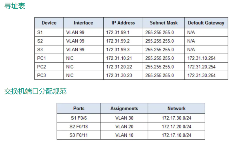
Port assignments are listed in the table at the beginning of the activity. Save the configuration after assigning the switch port to the VLAN.
S1(config)# interface f0/6

 switchport access vlan 30


S2(config)# interface f0/18

switchport access vlan 20


S3(config)# interface f0/11

switchport access vlan 10
Step 5: assign the relay to the local VLAN 99.
Use the corresponding commands to configure ports F0/1 to F0/4 on each switch as relay ports, and assign these relay ports to local VLAN 99.
S1(config)# interface range f0/1-4

switchport mode trunk

switchport trunk native vlan 99


S2(config)# interface range f0/1-4

switchport mode trunk

switchport trunk native vlan 99


S3(config)# interface range f0/1-4

switchport mode trunk

switchport trunk native vlan 99
Step 6: configure the management interface on all three switches using addresses.
S1(config)# interface vlan99

ip address 172.31.99.1 255.255.255.0


S2(config)# interface vlan99

ip address 172.31.99.2 255.255.255.0


S3(config)# interface vlan99

 ip address 172.31.99.3 255.255.255.0
Part 2: configuring spanning tree PVST + and load balancing
Step 1: configure STP mode.
Use the spanning tree mode command to configure switches so that they use PVST as the STP mode.
S1(config)# spanning-tree mode pvst


S2(config)# spanning-tree mode pvst


S3(config)# spanning-tree mode pvst
Step 2: configure the spanning tree PVST + load balancing.
Configure S1 as the primary root directory for VLANs 1, 10, 30, 50, and 70. Configure S3 as the primary root directory for VLANs 20, 40, 60, 80, and 99. Configure S2 as the secondary root of all VLANs.
S1(config)# spanning-tree vlan 1,10,30,50,70 root primary


S2(config)# spanning-tree vlan 1,10,20,30,40,50,60,70,80,99 root secondary


S3(config)# spanning-tree vlan 20,40,60,80,99 root primary
Part 3: configuring port express and BPDU protection
Step 1: configure the port speed on the switch.
PortFast enables the port to enter the forwarding state almost immediately by significantly reducing the time of listening and learning state. PortFast minimizes the time required for servers or workstations to come online. Configure PortFast on the switch interface connected to the PC.
S1(config)# interface f0/6

spanning-tree portfast


S2(config)# interface f0/18

 spanning-tree portfast


S3(config)# interface f0/11

spanning-tree portfast
Step 2: configure BPDU protection on the switch
The STP PortFast BPDU protection enhancement allows network designers to enforce STP domain boundaries and keep the active topology predictable. Devices behind STP ports with STP port express enabled cannot affect the STP topology. When receiving BPDU, the BPDU protection operation will disable the port configured with PortFast. BPDU protection converts the port to an error disabled state and displays a message on the console. Configure BPDU protection on the switch interface connected to PC.
S1(config)# interface f0/6

spanning-tree bpduguard enable


S2(config)# interface f0/18

spanning-tree bpduguard enable


S3(config)# interface f0/11

spanning-tree bpduguard enable