0x00 Preface
Because it was mentioned earlier that for the relevant pin test of HC32F460, the author recently completed a simplified SPI bus according to the device, so put it on the MCU to test the effect.
0x10 introduction
As an SPI simulator, he needs at least:
- A way of setting
- An interface to view the current status
- A write interface
- A read interface
The characteristics of SPI have been introduced earlier, and will not be repeated here:
typedef union
{
	unsigned char d8;
	struct
	{
	unsigned CPHA:1;		//0-even-catch|1-odd-catch
	unsigned CPOL:1;		//0-low|1-high
	unsigned DATASIZE:1;	//0-8bit|1-16bit
	unsigned FLASH_BIT:1;	//0-MSB|1-LSB
	unsigned MODE:1;		//0-master|1-slave
	unsigned DIR:2;		//0-Full duplex|1-onlyRX|2-onlyTX|3-Only_listen
	unsigned ENABLE :1; //0-off|1-on
	}b;

}S_SPI_CONFIG;
typedef struct
{
	unsigned CLK:1;
	unsigned CS:1;
	unsigned MOSI:1;
	unsigned MISO:1;
	unsigned NU :28;
}S_SPI_SOFT_PIN;
This is the current virtual device mode and pin modeling. Here, only Master and Mode 0 modes are implemented, and the remaining modes are not tested
Here, HC32F460 library does not have an interface for a single driver of the current GPIO, so the author has made one himself
void Port_Write_Pins(en_port_t enPort, uint16_t u16Pin,unsigned char state)
{
    uint16_t *PORx;
    if(state)
    {
        PORx = (uint16_t *)((uint32_t)(&M4_PORT->POSRA) + 0x10u * enPort);
    }
    else
    {
        PORx = (uint16_t *)((uint32_t)(&M4_PORT->PORRA) + 0x10u * enPort);
    }
    *PORx |= u16Pin;
}
A basic implementation is also required below, that is, to simulate the current SPI device using a timer model:
void TIM_IRQHandler()
    {
        {
            if(spi_soft_obj.config.b.ENABLE == 1)
            {
                //normal-no send
                if(spi_soft_obj.line_state == 0)
                {
                    if(spi_soft_obj.config.b.CPOL)
                    {
                        spi_pin.CLK = 1;
                    }
                    else
                    {
                        spi_pin.CLK = 0;
                    }
                    //spi_pin.MOSI = 0;
                    if(spi_pin.CS == 1)
                    {
                        //MSB
                        if(spi_soft_obj.config.b.FLASH_BIT == 0)
                        {
                            spi_soft_obj.data[SOFT_SPI_DATA_IN] |= MISO_GET();
                        }
                        //LSB
                        else
                        {   //no debug
                            spi_soft_obj.data[SOFT_SPI_DATA_IN] |= MISO_GET()<<((8*(spi_soft_obj.config.b.DATASIZE+1)));
                        }
                    }
                    spi_pin.CS = 0;
                    update_bit =0;
                    clock_count = 0;
                    spi_bit_count = 0;
                }
                //send-once byte
                else
                {
                        if((clock_count == 0))
                        {
                            spi_soft_obj.data[SOFT_SPI_DATA_IN] = 0;
                        }
                    //0-CPHA=0
                    if((!spi_soft_obj.config.b.CPHA) && (clock_count == 0))
                    {
                        update_bit = 1;
                        spi_pin.CLK = 0;
                    }
                    else
                    {
                        spi_pin.CLK = !spi_pin.CLK;
                        if((clock_count % 2) == (spi_soft_obj.config.b.CPHA))
                        {
                            update_bit = 1;
                        }
                        else
                            update_bit = 0;
                    }
                    clock_count++;
                    //send_finish
                    if((8*(spi_soft_obj.config.b.DATASIZE+1)) <= spi_bit_count)
                    {

                        spi_soft_obj.line_state = 0;
                        //spi_pin.MOSI = 0;
                        spi_pin.CS = 1;
                        update_bit =0;
                        clock_count = 0;
                        spi_bit_count = 0;
                    }
                    if(update_bit)
                    {
                        spi_pin.MISO = MISO_GET();
                        //MSB
                        if(spi_soft_obj.config.b.FLASH_BIT == 0)
                        {
                            spi_pin.MOSI = spi_soft_obj.data[SOFT_SPI_DATA_OUT] >> ((8*(spi_soft_obj.config.b.DATASIZE+1)) - spi_bit_count - 1 ) & 0x01;
                            spi_soft_obj.data[SOFT_SPI_DATA_IN] |= MISO_GET()<<((8*(spi_soft_obj.config.b.DATASIZE+1))- spi_bit_count );
                        }
                        //LSB
                        else
                        {   //no debug
                            spi_pin.MOSI = spi_soft_obj.data[SOFT_SPI_DATA_OUT] >> (spi_bit_count) & 0x01;
                            spi_soft_obj.data[SOFT_SPI_DATA_IN] |= MISO_GET()<<(spi_bit_count);
                        }
                        spi_bit_count++;
                    }


                }
                CLK_SET(spi_pin.CLK);
                MOSI_SET(spi_pin.MOSI);

            }
            else
            {
                CLK_SET(0);
                MOSI_SET(0);
            }
        }
    }
Here we have got a basic device simulation code. As long as the interface of the timer is connected, SPI communication can be realized directly. Here, the author selects PB 6 7 8 9 as the IO port
void spi_soft_init()
    {
        stc_port_init_t port_init_struct;
        port_init_struct.enPinMode = Pin_Mode_Out;
        port_init_struct.enPullUp = Enable;
        port_init_struct.enLatch = Disable;
        port_init_struct.enExInt = Disable;
        port_init_struct.enInvert = Disable;
        port_init_struct.enPullUp = Enable;
        port_init_struct.enPinDrv = Pin_Drv_H;
        port_init_struct.enPinOType = Pin_OType_Cmos;
        port_init_struct.enPinSubFunc = Enable;


        PORT_Init(PortB, Pin06, &port_init_struct);
        PORT_Init(PortB, Pin07, &port_init_struct);
        PORT_Init(PortB, Pin08, &port_init_struct);
        port_init_struct.enPinMode = Pin_Mode_In;
        port_init_struct.enPinOType = Pin_OType_Od;
        port_init_struct.enPullUp = Disable;
        PORT_Init(PortB, Pin09, &port_init_struct);
        //PORT_SetFunc(PortA,Pin05, Func_Tima0, Enable);

        //TIM -- simulate the current frequency


        spi_soft_obj.config.b.ENABLE = 1;


    timer_id = timer_add(
                        0,
                        0,
                        0,
                        0,
                        0,
                        1,
                        0,
                        1,
                        0,
                        TIM_IRQHandler
                        );

    }
It is not known which port does what work. Therefore, the author uses the macro definition here for constraints, which is also convenient for later maintenance. This is only an example. You can also replace the macro definition of GPIO more accurately.
#define CS_HIGH do{PORT_SetBits(PortB, Pin06);}while(0)
#define CS_LOW do{PORT_ResetBits(PortB, Pin06);}while(0)

#define CLK_SET(state) do{Port_Write_Pins(PortB, Pin07, state);}while(0)


#define MOSI_SET(state) do{Port_Write_Pins(PortB, Pin08, state);}while(0)
#define MISO_GET() (PORT_GetBit(PortB,Pin09))
Finally, the external interfaces are required:
char SPI_GetBusBusy()
{
	while(spi_pin.CS || spi_soft_obj.line_state);
	return spi_pin.CS && spi_soft_obj.line_state;
}

void SPI_SendData(unsigned short data)
{
	if((spi_soft_obj.config.b.ENABLE) && (!spi_soft_obj.config.b.MODE))
		spi_soft_obj.data[SOFT_SPI_DATA_OUT] = data;
	spi_soft_obj.line_state = 1;
}

unsigned short SPI_ReceiveData()
{
	unsigned short data = 0x00;
	data = spi_soft_obj.data[SOFT_SPI_DATA_IN];
	spi_soft_obj.data[SOFT_SPI_DATA_IN] = 0;


	return data;
}
This completes the modeling of an SPI device. The replacement pin only needs to replace the pin position of macro definition and initialization.
The author can directly get the current test results by using the logic analyzer of Mengyuan. The following figure shows the specific situation of 25KHz
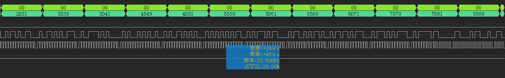
It can be seen that the current character accumulation result is correct and can be used.
0x20 summary
This article starts from Note: introduction and actual effect of simulated SPI , more articles can be found in my blog.