Notes on OSPF dynamic routing protocol (8): examples of comprehensive application of OSPF Protocol
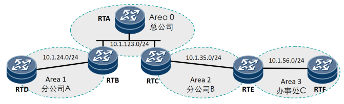
The company's network topology is shown in the following figure: the basic configuration of OSPF has been completed. As a network administrator, there are several problems to be solved:
l. the communication between the head office and branches A and B is normal, but it is unable to communicate with office C.
l. the equipment performance of branch A is low. It is hoped to reduce the pressure of routing calculation and storage. At the same time, considering the network expansion, it is necessary to retain the function of introducing external routing.
There are many outsiders in office C, so a more secure way is adopted to ensure the security of routing interaction.
l) when introducing external routing into RTA, in addition to the external overhead, the overhead in OSPF domain should also be considered.
Basic configuration (including port address and OSPF process configuration). See the configuration below for details
Router RTA configuration:
#
interface GigabitEthernet0/0/0
 ip address 10.1.123.1 255.255.255.0
#
interface LoopBack0
 ip address 1.1.1.1 255.255.255.255
#
ospf 1 router-id 1.1.1.1
 area 0.0.0.0
  network 1.1.1.1 0.0.0.0
  network 10.1.123.0 0.0.0.255
#
Router RTB configuration:
#
interface GigabitEthernet0/0/0
 ip address 10.1.123.2 255.255.255.0
#
interface GigabitEthernet0/0/1
 ip address 10.1.24.2 255.255.255.0
#
interface LoopBack0
 ip address 2.2.2.2 255.255.255.255
#
ospf 1 router-id 2.2.2.2
 area 0.0.0.0
  network 2.2.2.2 0.0.0.0
  network 10.1.123.0 0.0.0.255
 area 0.0.0.1
  network 10.1.24.0 0.0.0.255
#
Router RTC configuration:
#
interface GigabitEthernet0/0/0
 ip address 10.1.123.3 255.255.255.0
#
interface GigabitEthernet0/0/1
 ip address 10.1.35.3 255.255.255.0
#
interface LoopBack0
 ip address 3.3.3.3 255.255.255.255
#
ospf 1 router-id 3.3.3.3
 area 0.0.0.0
  network 3.3.3.3 0.0.0.0
  network 10.1.123.0 0.0.0.255
 area 0.0.0.2
  network 10.1.35.0 0.0.0.255
#
Router RTD configuration:
#
interface GigabitEthernet0/0/0
 ip address 10.1.24.4 255.255.255.0
#
interface LoopBack0
 ip address 4.4.4.4 255.255.255.255
#
ospf 1 router-id 4.4.4.4
 area 0.0.0.1
  network 4.4.4.4 0.0.0.0
  network 10.1.24.0 0.0.0.255
#
Router RTE configuration:
#
interface GigabitEthernet0/0/0
 ip address 10.1.35.5 255.255.255.0
#
interface GigabitEthernet0/0/1
 ip address 10.1.56.5 255.255.255.0
#
interface LoopBack0
 ip address 5.5.5.5 255.255.255.255
#
ospf 1 router-id 5.5.5.5
 area 0.0.0.2
  network 5.5.5.5 0.0.0.0
  network 10.1.35.0 0.0.0.255
 area 0.0.0.3
  network 10.1.56.0 0.0.0.255
#
Router RTF configuration:
#
interface GigabitEthernet0/0/0
 ip address 10.1.56.6 255.255.255.0
#
interface LoopBack0
 ip address 6.6.6.6 255.255.255.255
#
ospf 1 router-id 6.6.6.6
 area 0.0.0.3
  network 6.6.6.6 0.0.0.0
  network 10.1.56.0 0.0.0.255
#
Demand 1 Analysis: Office C is in Area 3, and the left side of RTE is connected with Area 2. According to the connection rules between OSPF backbone area and non backbone area, the reason why it cannot pass normally is that Area 3 is not directly connected to Area 0. The solution is to establish a virtual connection between RTE and RTC.
The router RTC is configured as follows:

The router RTE is configured as follows:

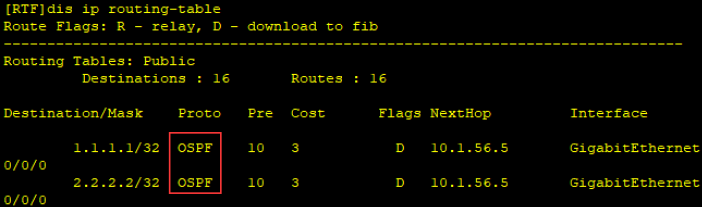
After configuration, you can view the RTF routing table and find that you have learned OSPF routing.
Viewing OSPF neighbor relationship establishment, you can see that RTF has established OSPF neighbors with RTE.
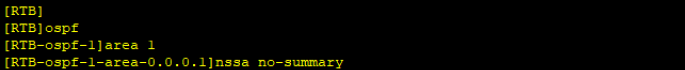
Demand 2 Analysis: the RTD performance of the internal equipment in area 1 is low. To reduce the routing calculation pressure, you can use Stub, total Stub, NSSA and total NSSA to minimize the need to select total Stub or total NSSA. At the same time, in order to retain the functions introduced by external routes, only total NSSA can be selected.
Router RTD configuration is as follows:

The router RTB configuration is as follows:
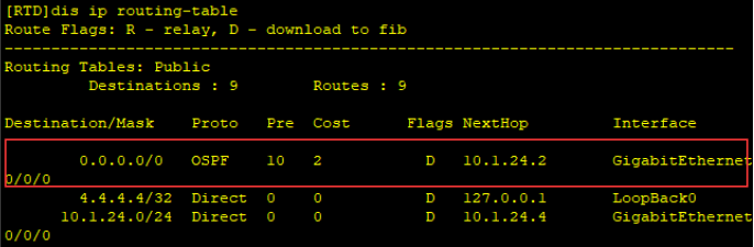
After configuration, you can view the routing table of RTD and find that all routes outside the area are summarized as a default route to ABR (area boundary router) RTB.
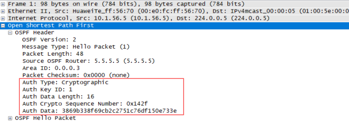
Requirement 3 Analysis: authentication is required to ensure routing security. The safest authentication mode is HMAC-MD5. The authentication form is interface authentication.
Router RTE configuration is as follows:

The router RTF configuration is as follows:

After configuration, capture the packet and view the OSPF HELLO message header to see the authentication field.
Requirement 4 Analysis: when calculating external routes, if you want to consider the overhead in the OSPF domain, you can implement it by introducing an external route of type 1.
The router RTA configuration is as follows:
